
Lsx wiring for dumb ass
 12-30-2012, 01:31 PM
#21
Staging Lane
Thread Starter
So the pins I removed from the blue plug were
23, 25, 28, 32, 33, 34, 45, 46, 53, 55, 65, 68, 70
then i removed from the red plug
2, 4, 6, 7, 8, 13, 14, 17, 18, 30, 34, 36, 37, 41, 42, 43, 45, 47, 48, 51, 53, 54, 63, 64, 70...
if i missed something let me know, i am now tracing back the wires but some lead to plugs that still have wires leading in to the harness...hmmmm
 12-30-2012, 07:37 PM
#22
Teching In

Join Date: Dec 2012
Posts: 4
Likes: 0
Received 0 Likes
on
0 Posts
I also agree with the Megasquirt... But if you must do it by hand be sure to take your time. Dont rush it, wire each slowly, and be sure to wire and hide correctly the first time. I am ripping out all of my previous wiring now just to tuck and hide everything correctly...
12-30-2012, 11:24 PM
#23
On The Tree
iTrader: (2)

Join Date: Mar 2007
Location: Michigan
Posts: 131
Likes: 0
Received 0 Likes
on
0 Posts
What is the harness do you have?, Is it from a F-Body or a tuck?
The White, Blue & should be a Black plug coming out of the ECU are the C plugs that connect the inner harness (gauges, OBD Port, ect.) to the PCM.
I hope I'm not off track in saying this but the Pin-out from the LT1 swap is to make a LT1 run with a LS PCM ( I did this to my 93) and might get you off track since you are running a LS motor and not a LT.
You need to pin it as a LS motor and the LT1 swap pin-out it will get you backwards if you follow the Injector pin-out out for sure.
As as far as the PCM goes, yes you will have to have it reprogrammed to remove the VATS, Trans and any other sensors and what not that you removed or not using turned off and upgraded for any changes like No2 or cam.
12-31-2012, 07:14 AM
#24
Staging Lane
Thread Starter
I have a Harness from a 2000 F Body with a standard, I didnt see a lot of the trans wires being used either(Trans fluid temp, trans fluid pressure, etc...)
[IMG]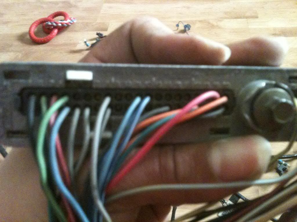 [/IMG]
I just pulled the pins out from here.
I have my motor together n will be plugging it up in the engine craddle n routing all the wires to enter the firewall on the pass side if the motor so I can mount everything in the Glove box(OBD port, ECU, Fuse Block, Relays, etc...)
Here is the car
[IMG]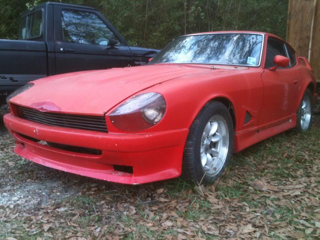 [/IMG]
Here is the Motor as it sits right now in my Kitchen
[IMG]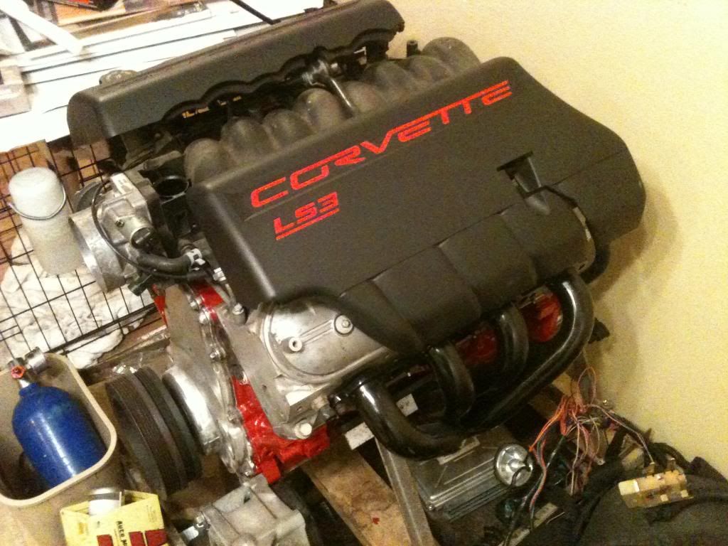 [/IMG]
These are the plugs in question
[IMG]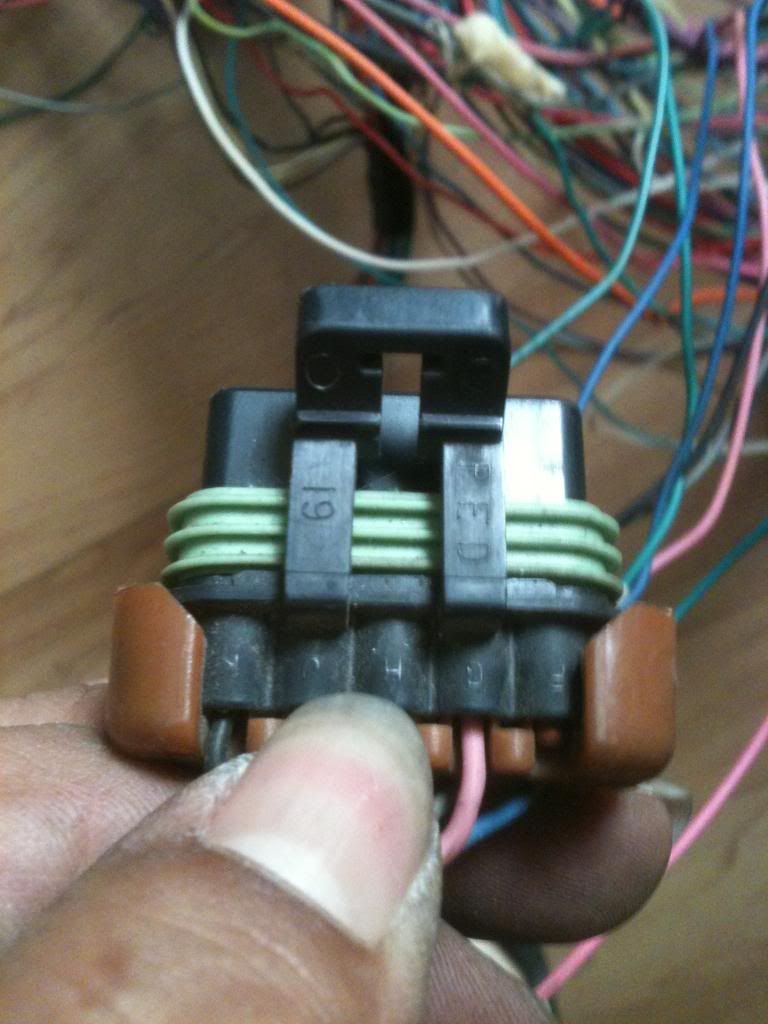 [/IMG]
[IMG]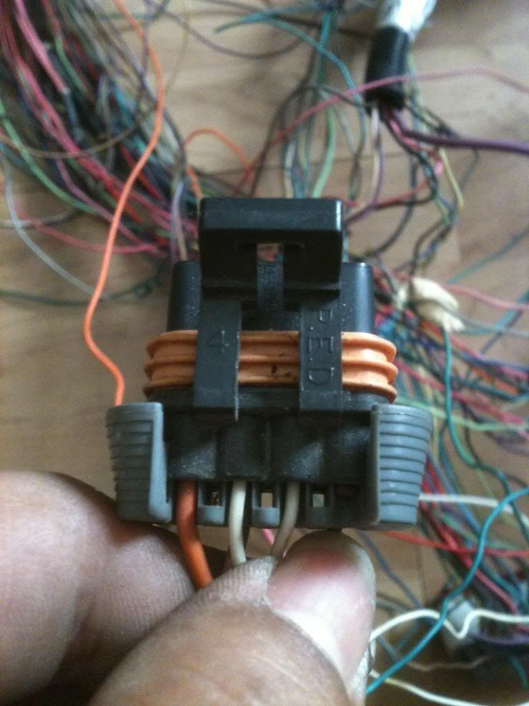 [/IMG]
[IMG]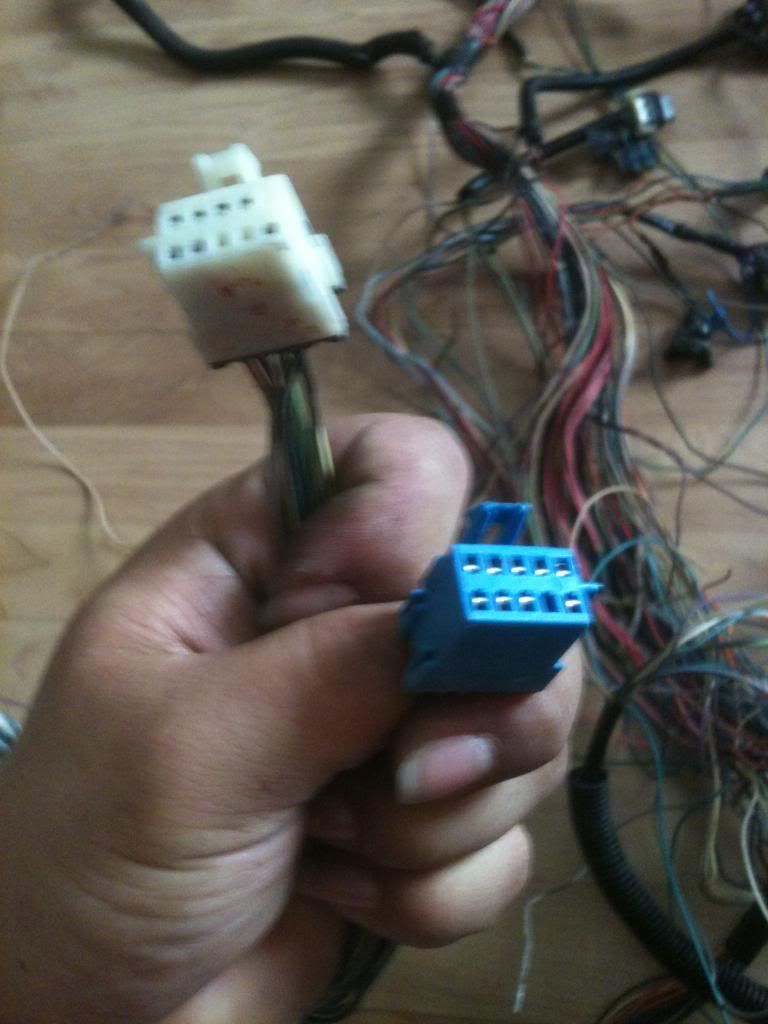 [/IMG]
So the question is, once I am happy with how it is routed, I will prolly have to cut the wires, untangle them so they lay straight the solder n heat shrink them back together right?
Then with these left over plugs i will keep what wires out of them n throw the rest awy?
[IMG]
[/IMG]I just pulled the pins out from here.
I have my motor together n will be plugging it up in the engine craddle n routing all the wires to enter the firewall on the pass side if the motor so I can mount everything in the Glove box(OBD port, ECU, Fuse Block, Relays, etc...)
Here is the car
[IMG]
[/IMG]Here is the Motor as it sits right now in my Kitchen
[IMG]
[/IMG]These are the plugs in question
[IMG]
[/IMG][IMG]
[/IMG][IMG]
[/IMG]So the question is, once I am happy with how it is routed, I will prolly have to cut the wires, untangle them so they lay straight the solder n heat shrink them back together right?
Then with these left over plugs i will keep what wires out of them n throw the rest awy?
12-31-2012, 09:27 AM
#26
On The Tree
iTrader: (2)
Join Date: Mar 2007
Location: Michigan
Posts: 131
Likes: 0
Received 0 Likes
on
0 Posts
Can you get me a good pic of the first 2 pics and the wires that come out of them?
I believe that they are your C100 witch should have the cooling fan switch wires & your C105 and that should have the Fused Ignition wire.
Those White & Blue ones are C plugs also.
The White (Natural) one has a Ignition fused wire in it.
The Blue one is going to have a Serial Data wire in it.
I can help ya more as soon as I know about the 2 black plugs and what color the wires are.
12-31-2012, 10:26 AM
#27
Staging Lane
Thread Starter
[IMG]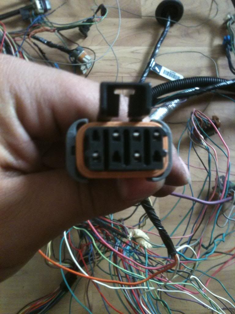 [/IMG]
Pink orange white n white are coming out of this one
[IMG]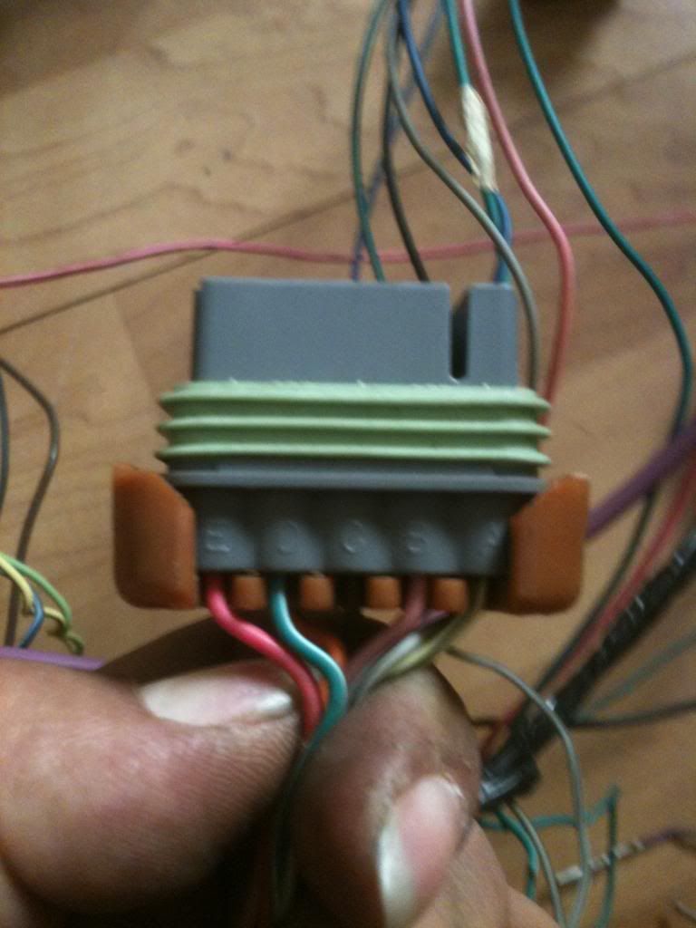 [/IMG]
[IMG]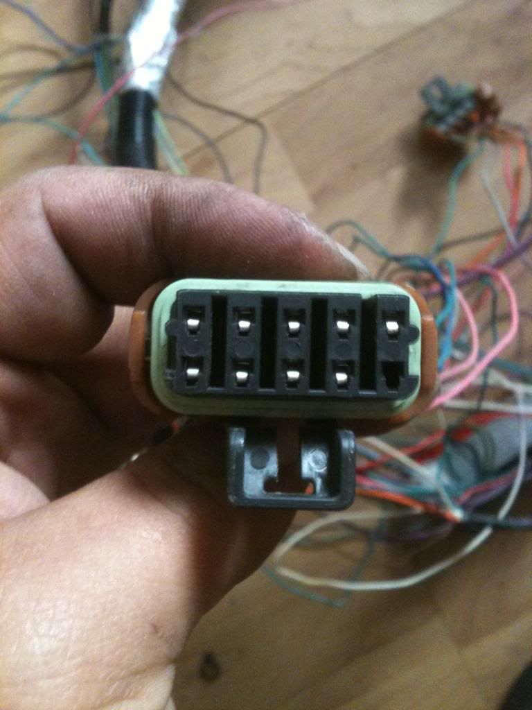 [/IMG]
Pink, Green, Grey, yellow, orange, n those are the wires i Can see in pics for now, at work right now
Here is another pic for fun, notice the blue bottle?
[IMG]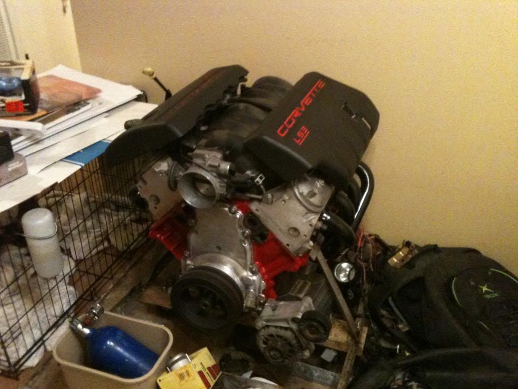 [/IMG]
[/IMG]Pink orange white n white are coming out of this one
[IMG]
[/IMG][IMG]
[/IMG]Pink, Green, Grey, yellow, orange, n those are the wires i Can see in pics for now, at work right now
Here is another pic for fun, notice the blue bottle?
[IMG]
[/IMG]
12-31-2012, 01:01 PM
#30
On The Tree
iTrader: (2)
Join Date: Mar 2007
Location: Michigan
Posts: 131
Likes: 0
Received 0 Likes
on
0 Posts
2nd & 3rd Pic C105
Pin A Pink Fused Feed Input
Pin B DK Green/White A/C Compressor Relay Control
Pin C DK Green A/C Compressor Clutch Solenoid Feed
Pin D Gray Reference Voltage Feed - 5 Volt Reference
Pin E DK Blue Throttle Position Sensor Signal
Pin F I believe yours is empty
Pin G Pink Fused Input Feed
Pin H DK Blue Coolant Fan Relay Control
Pin J DK Green Coolant Fan Relay Control
Pin K Black Sensor Return
This is what those wires do/did in a F-Body.
I will search my schematics that I have to find out what some of the fused Feeds linked to.
You will want anything that is Pink for ignition for sure.
12-31-2012, 01:23 PM
#35
Staging Lane
Thread Starter
Cause this is what is available n the budget wont allow me to buy a complete on right now. Gonna wait on all that hassle n e ways. I do have a t5 but I need either a custom($$$$) bellhousing or a custom flywheel($$$). bith not in budget. Going to run the TH350 for now with a JEGS flywheel spacer n a 3000 stall
12-31-2012, 04:44 PM
#36
On The Tree
iTrader: (2)
Join Date: Mar 2007
Location: Michigan
Posts: 131
Likes: 0
Received 0 Likes
on
0 Posts
Well since you are going to do a 6Speed I would take all the 6Speed wires for the trans and just tuck them down under the car.
I wouldn't cut them unless you don't want those options with that transmission.
I wouldn't cut them unless you don't want those options with that transmission.
01-01-2013, 09:23 PM
#38
Staging Lane
Thread Starter
A 1973 Datsun(Nissan) 240z.
From the car
Headlights, brake lights, running lights, turn signals, hazard lights,
Horn, are what I need from the car.
Maybe I should buy a regular hot rod harness n wire the engine harness into the fuse panel??
From the car
Headlights, brake lights, running lights, turn signals, hazard lights,
Horn, are what I need from the car.
Maybe I should buy a regular hot rod harness n wire the engine harness into the fuse panel??
01-01-2013, 09:26 PM
#39
Staging Lane
Thread Starter
A real neat trick would be a under hood LED strip around the engine bay just in case
I'd I am at the track or on the road n at night I have to do something I can see under the hood, no drop light needed, maybe same in car
I'd I am at the track or on the road n at night I have to do something I can see under the hood, no drop light needed, maybe same in car
01-04-2013, 07:46 AM
#40
Staging Lane
Thread Starter
So I have the Harness broke down n am still wondering where to go from there. Will post pics later today. I have the sensors on the motor plugged in n wires laying on side.
What is absolutly needed to make these cars run?
Is VSS needed?
IAT?
MAF?
I would think the O2's would be the last sensors on the harness?
What is absolutly needed to make these cars run?
Is VSS needed?
IAT?
MAF?
I would think the O2's would be the last sensors on the harness?