86 Fiero GT w/ SBC/HSR/24X conversion
 06-14-2014, 05:13 PM
#1


About a year ago a Fiero buddy dropped off his carbed SBC Fiero for a refresh and conversion to EFI.
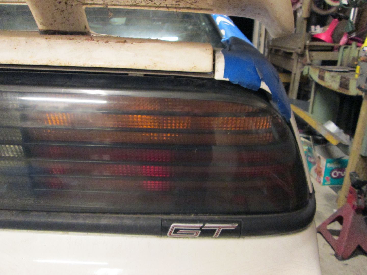
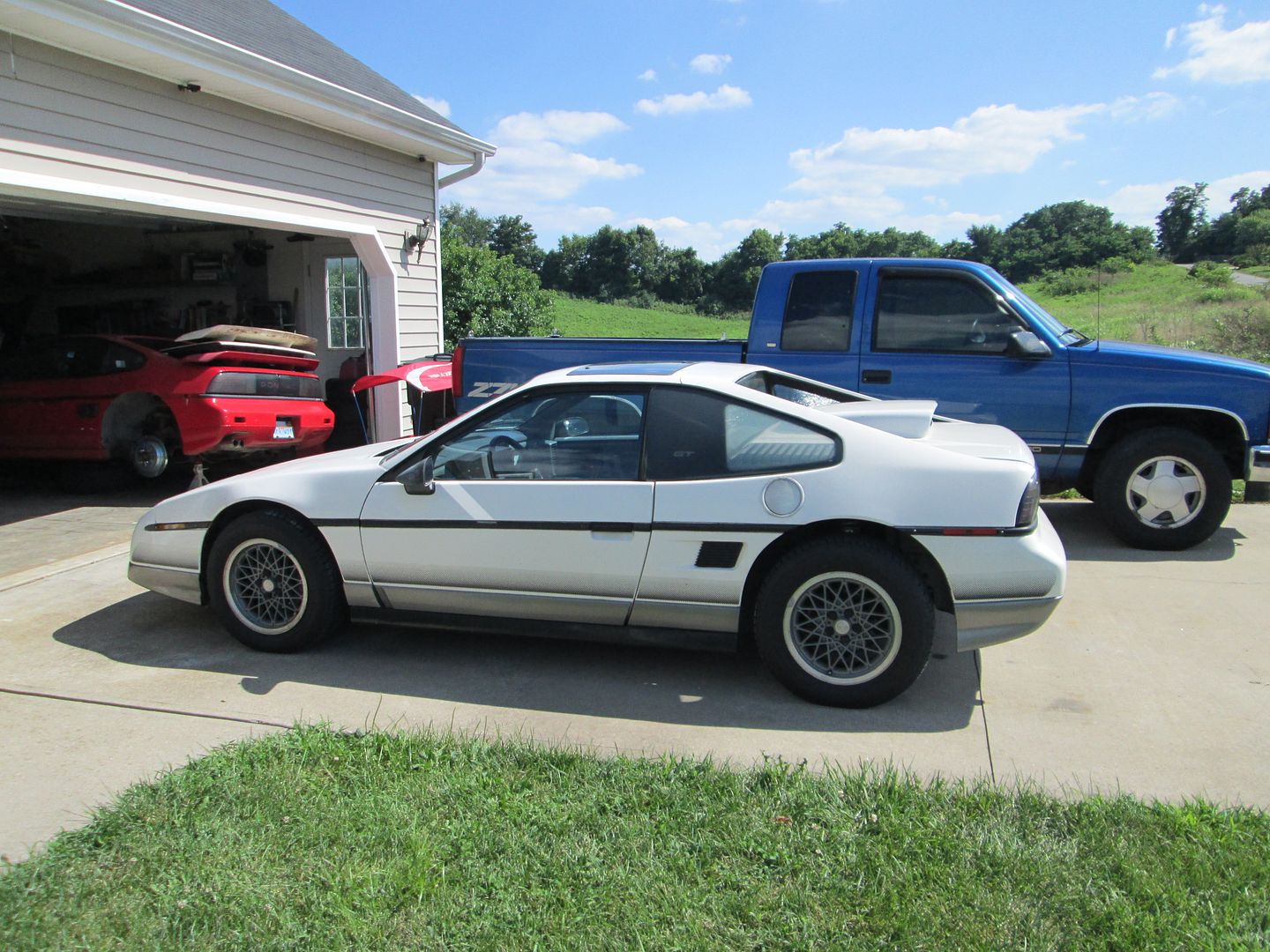
Here is the car (white Fastback GT) when it was dropped off:
Here is the engine bay with the carb:

The engine:
96+ Roller cam 350 four bolt main block bored to 355 ci.
JE Flattop forged piston
10:1 compression
Forged connecting rods and crankshaft from Ohio Crankshaft ( http://www.ohiocrank.com/home.html both made from 4340 steel)
Comp Cams 280 XFI HR13
AFR 195cc heads
1.5 Roller Rockers
With the carb, the engine dyno'd 371 whp.
Planned upgrades:
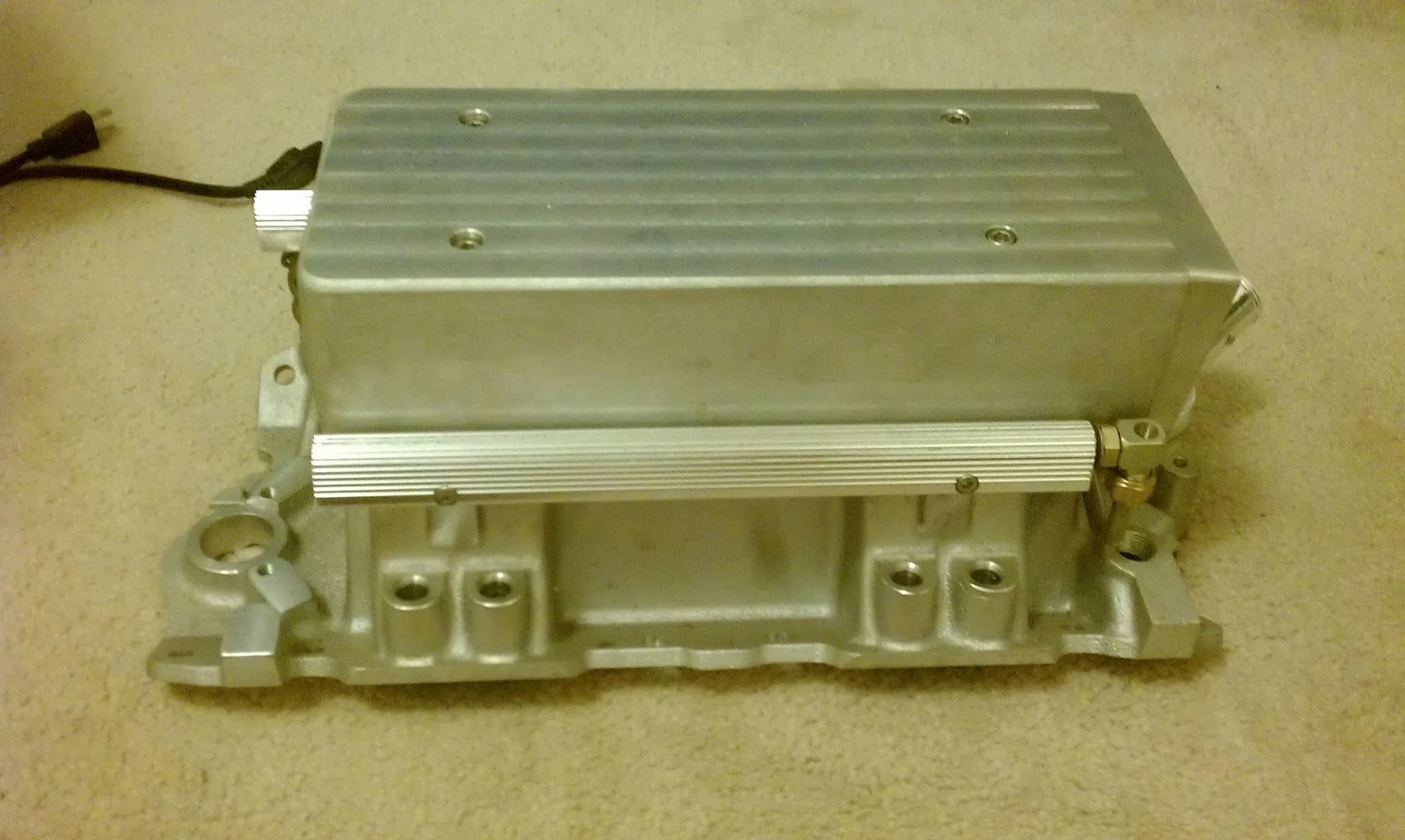
Modified HSR intake - total height is 8 15/16" (lower base machined, bottom of plenum machined, top of plenum machined)
58mm TPI Trottle body
36# Bosch Injectors
EFI Connection 24X conversion
1.6 roller rockers
1 3/4" mid length headers
LS2/4 coils
Serpentine belt upgrade
Drivetrain lowered to fit HSR under decklid
Clean, clutter free, detail oriented engine bay
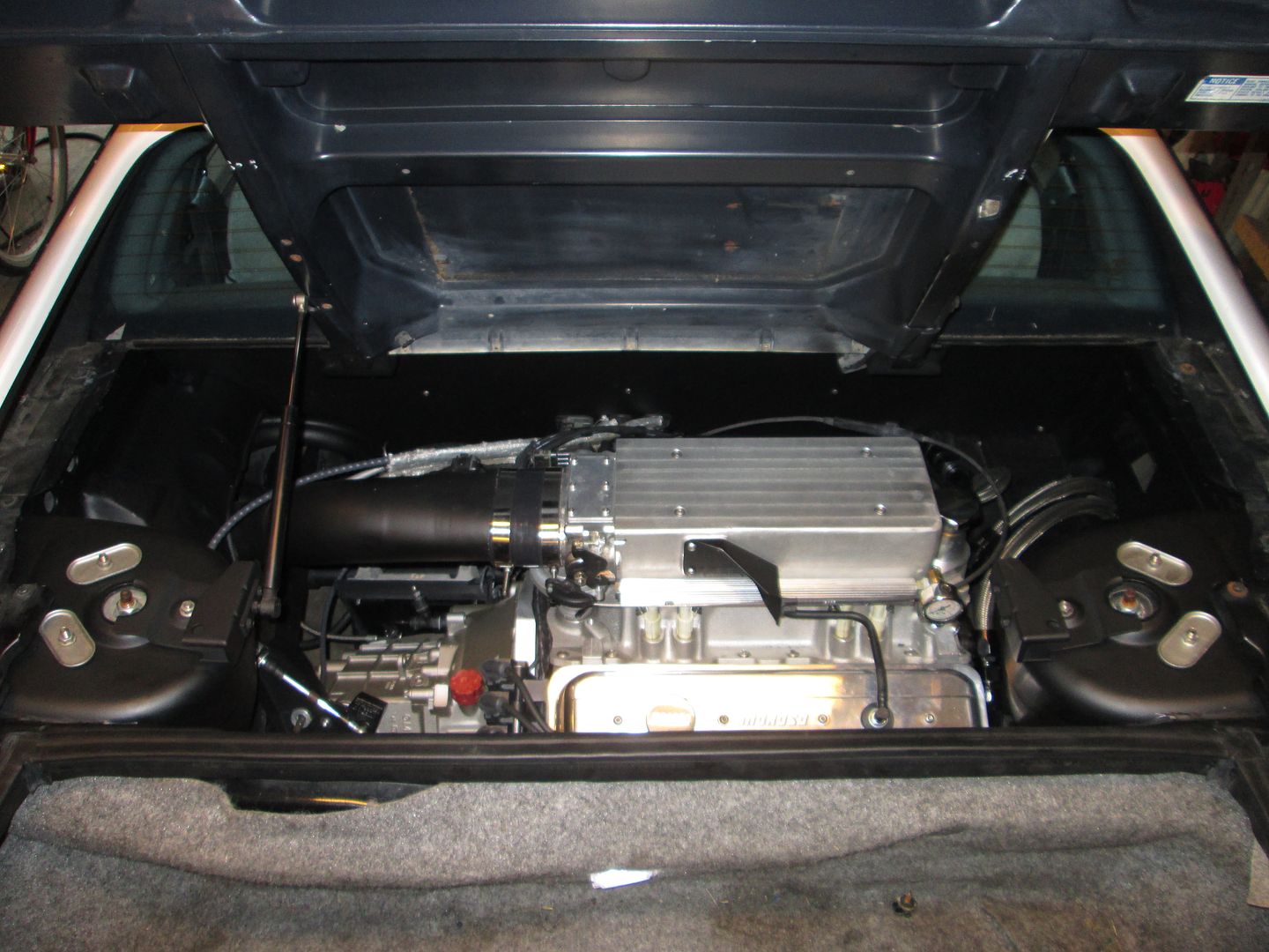
First order of business was to remove the old intake and do a preliminary test fit of the HSR. Here is the shortened HSR:
HSR on the engine (shifted to the rear of the block so the decklid could close):
Mark of bottom of decklid on HSR plenum... drivetrain needs to be lowered:
Now that I knew how much lower the engine needed to be, it was time to remove the drivetrain:
Here is the car (white Fastback GT) when it was dropped off:
Here is the engine bay with the carb:
The engine:
96+ Roller cam 350 four bolt main block bored to 355 ci.
JE Flattop forged piston
10:1 compression
Forged connecting rods and crankshaft from Ohio Crankshaft ( http://www.ohiocrank.com/home.html both made from 4340 steel)
Comp Cams 280 XFI HR13
AFR 195cc heads
1.5 Roller Rockers
With the carb, the engine dyno'd 371 whp.
Planned upgrades:
Modified HSR intake - total height is 8 15/16" (lower base machined, bottom of plenum machined, top of plenum machined)
58mm TPI Trottle body
36# Bosch Injectors
EFI Connection 24X conversion
1.6 roller rockers
1 3/4" mid length headers
LS2/4 coils
Serpentine belt upgrade
Drivetrain lowered to fit HSR under decklid
Clean, clutter free, detail oriented engine bay
First order of business was to remove the old intake and do a preliminary test fit of the HSR. Here is the shortened HSR:
HSR on the engine (shifted to the rear of the block so the decklid could close):
Mark of bottom of decklid on HSR plenum... drivetrain needs to be lowered:
Now that I knew how much lower the engine needed to be, it was time to remove the drivetrain:
 06-14-2014, 05:42 PM
#2
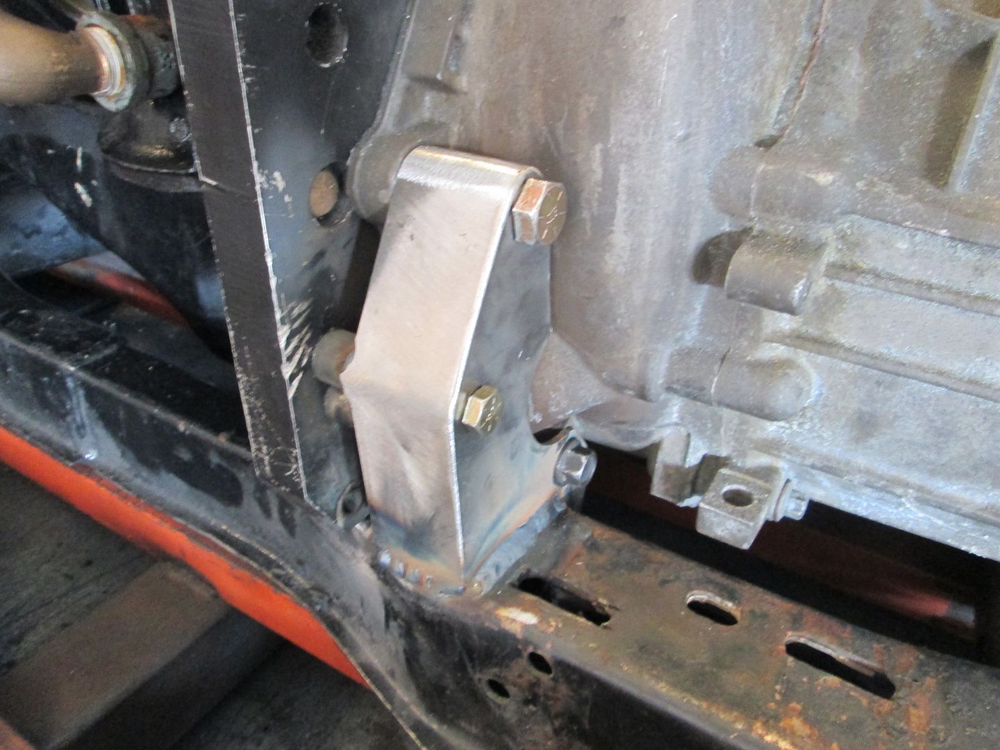
To lower the drivetrain the engine mount, A/C mount would need to be modified and the rear transmission mounts just needed remade entirely.
The V8 Archie engine mount needed to have about 1/2" cut off from the bottom:
I drilled 2 new mounting holes at the lower corners, welded up the half holes left from the original mounting holes, and installed it using the lowest set of holes:
The A/C bracket needed a 5th hole drilled into it (the bottom hole) it could be shifted upwards slightly to clear the cradle:
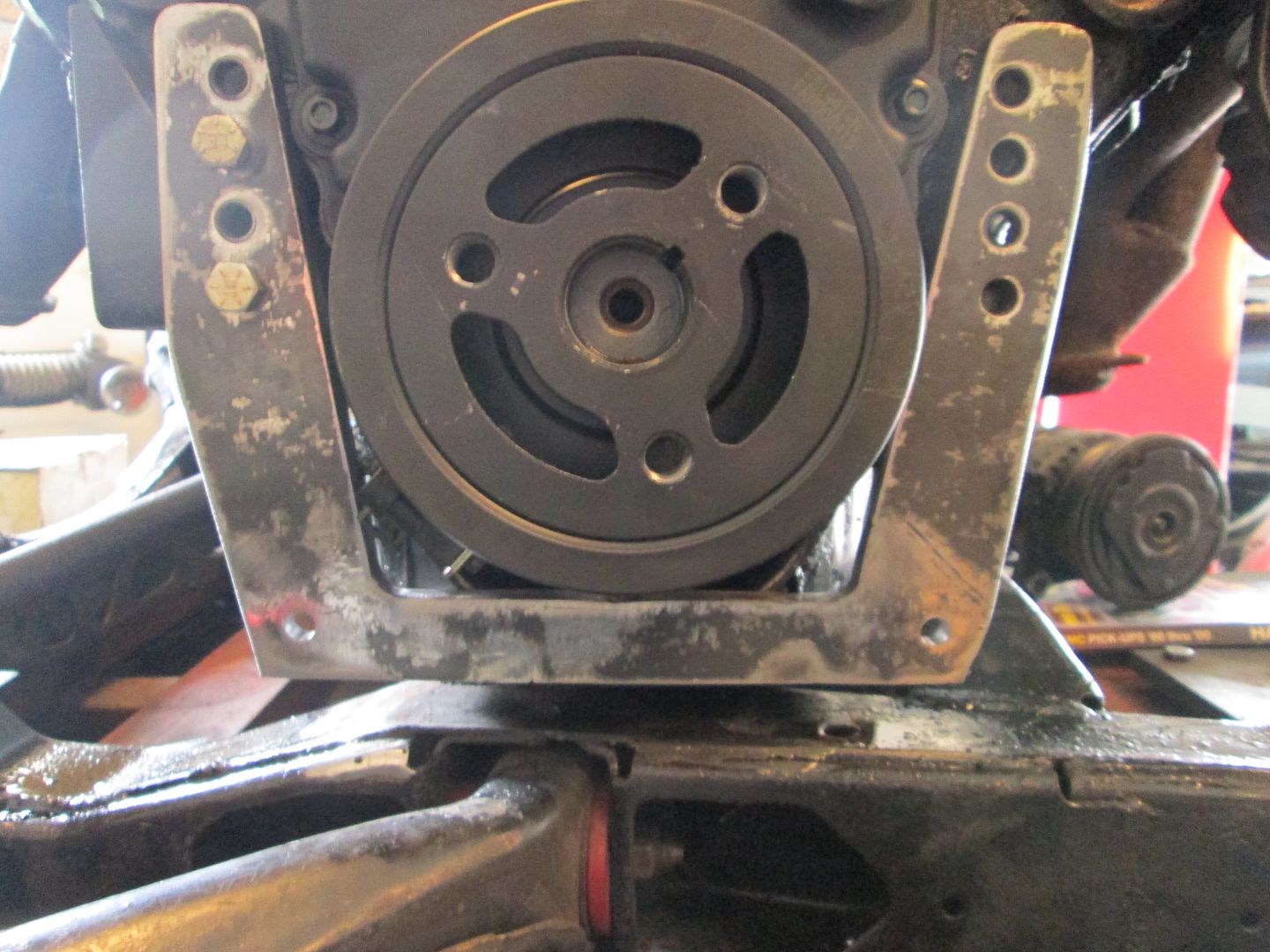
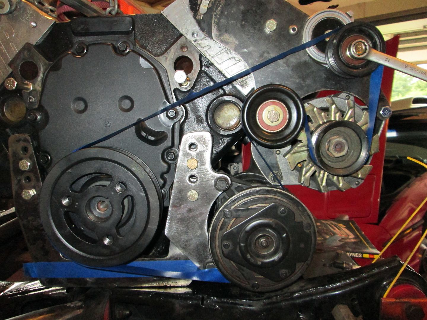
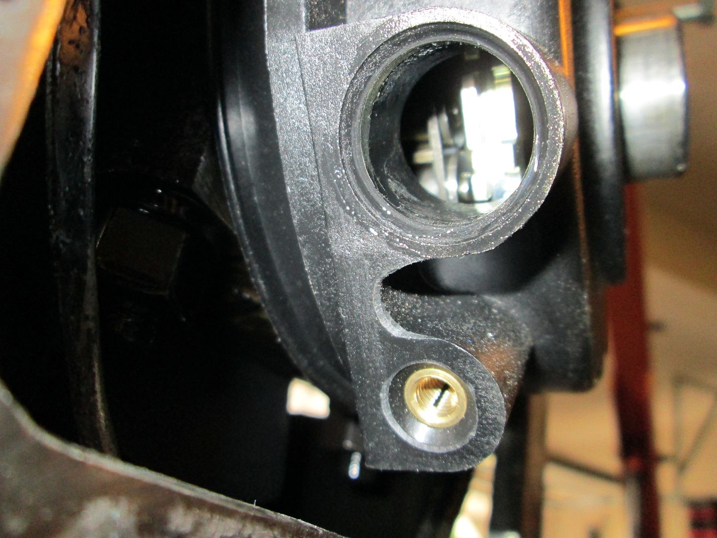
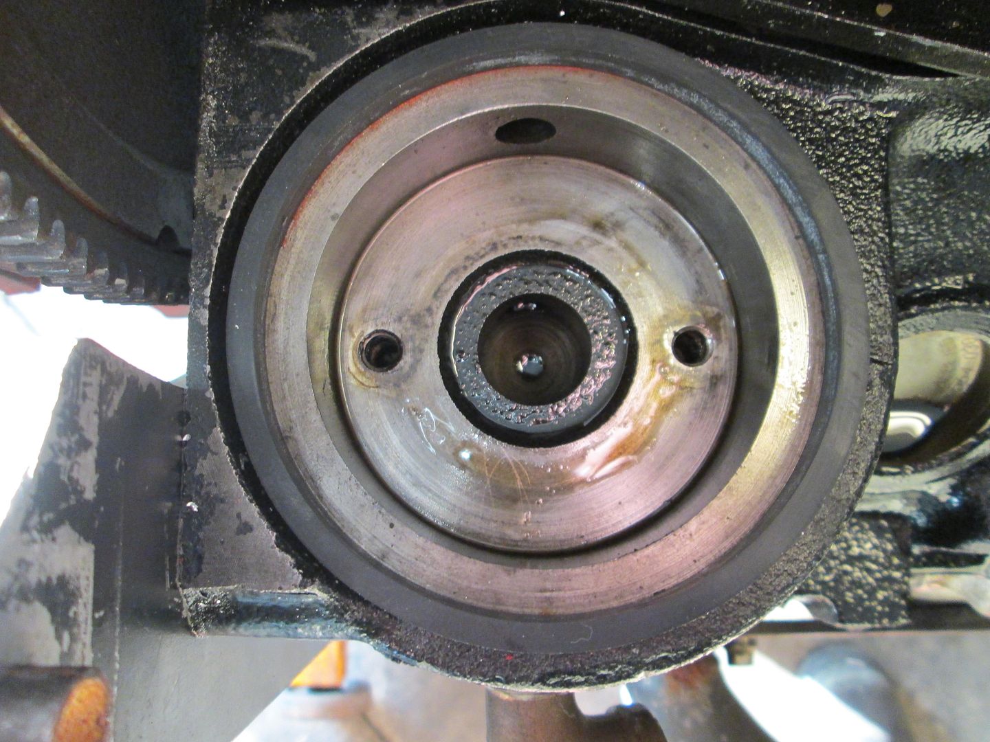
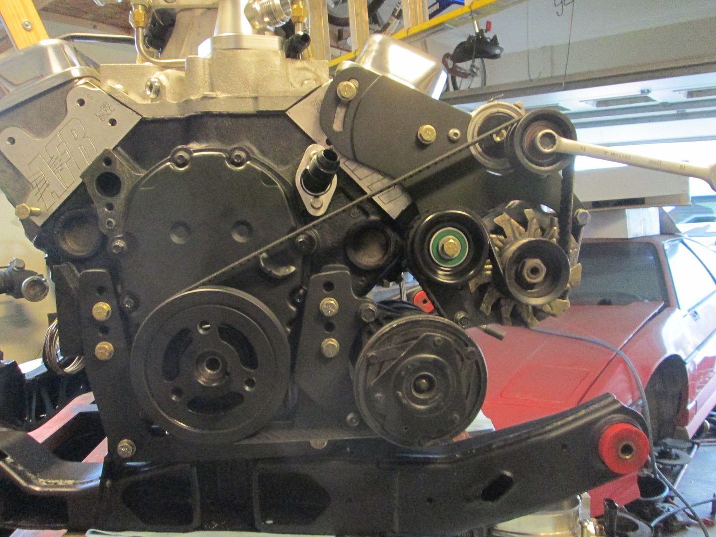
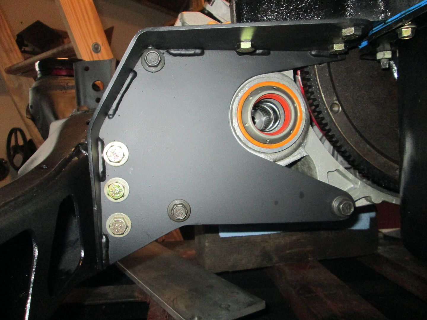
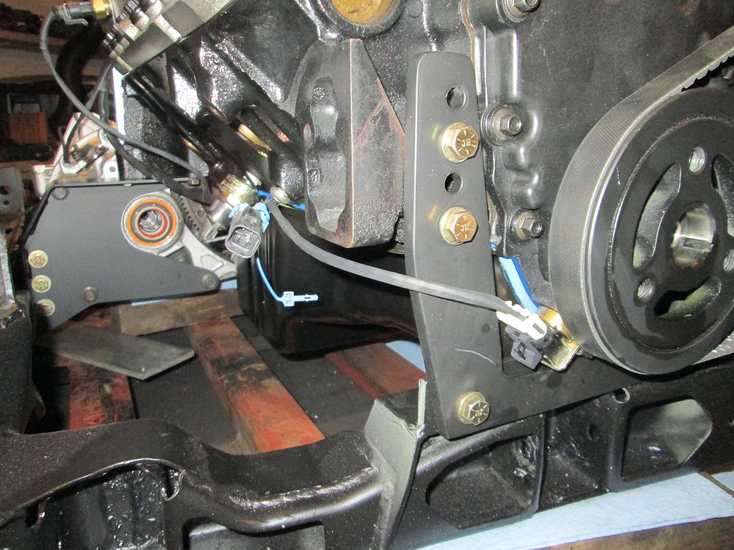
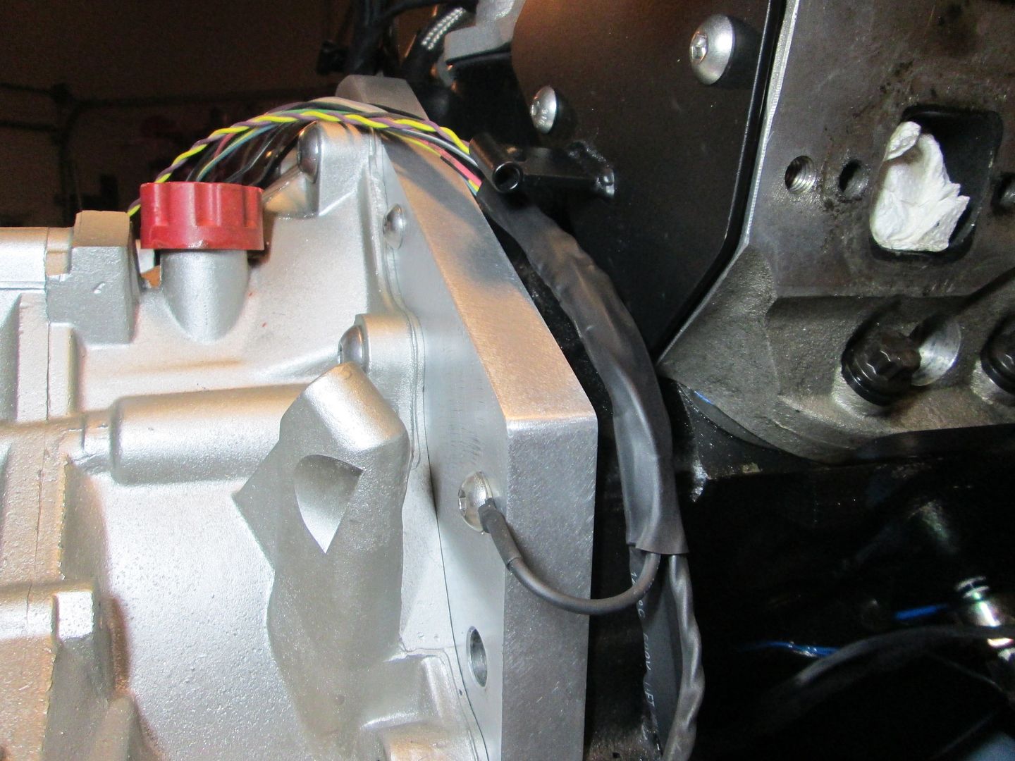
While working on the front engine mounts, I also knocked out the serpentine belt conversion. The V8 Archie kit uses a V-belt. The serpentine balancer used for this swap is from an 89+ FDW 2.5L 4 cylinder. It is a direct bolt on for the SBC and places the belt drive as tight to the timing cover as possible.
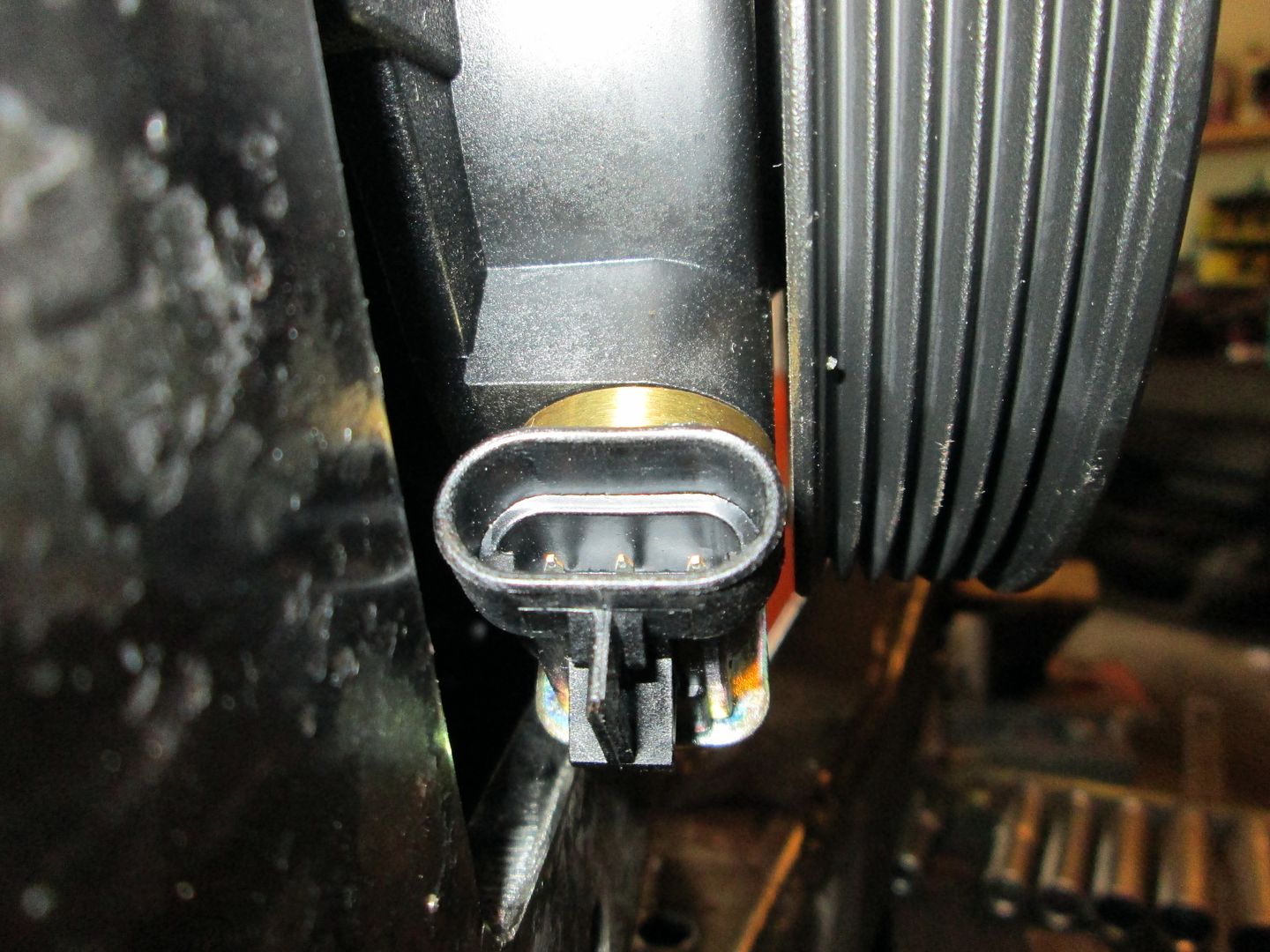
It is a tight fit for the crankshaft sensor between the front engine mount and the balancer. You can also see how close the balancer is to the L31 timing cover:
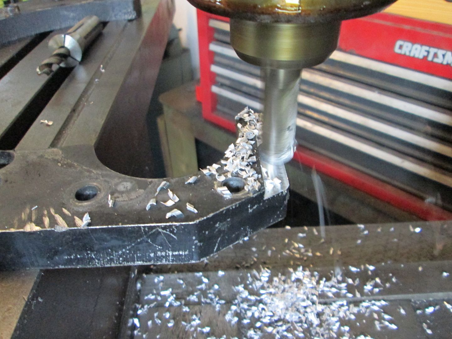
The rest of the serpentine conversion requires swapping the pulleys on the AC compressor and alternator. Then notching the V8 Archie alternator mount for a 3.1L Camaro belt tensioner and using an existing hole to mount the other idler pulley. Once done is will look something like this:
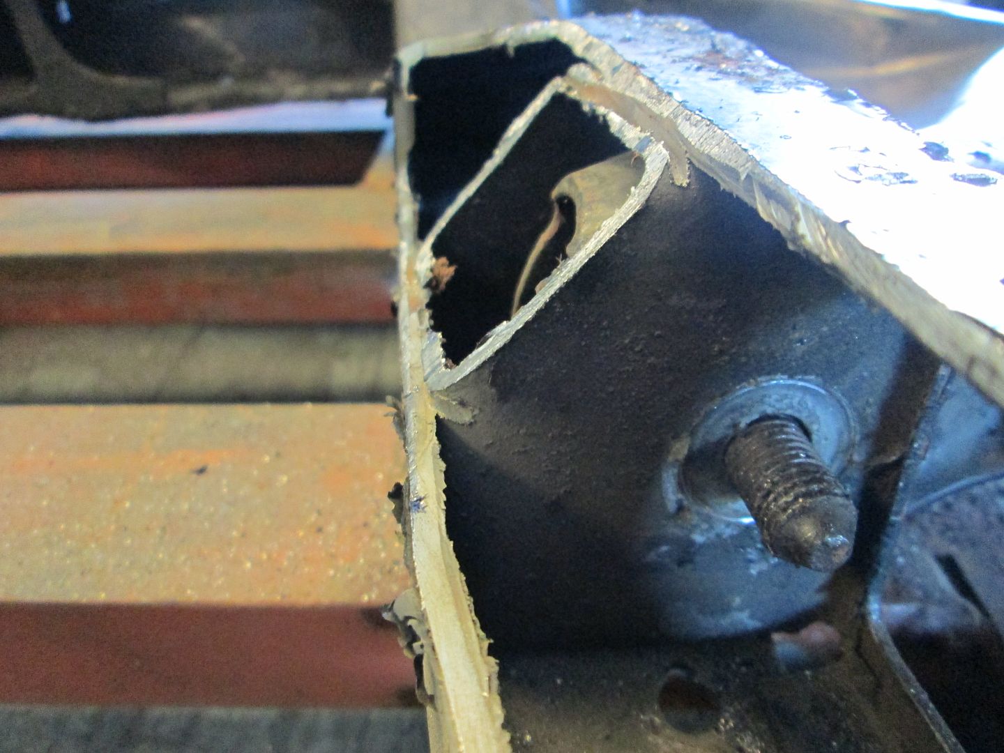
Moving on to the other side of the drivetrain, the lower edge of the V8 Archie adapter plate needed to be trimmed down further:
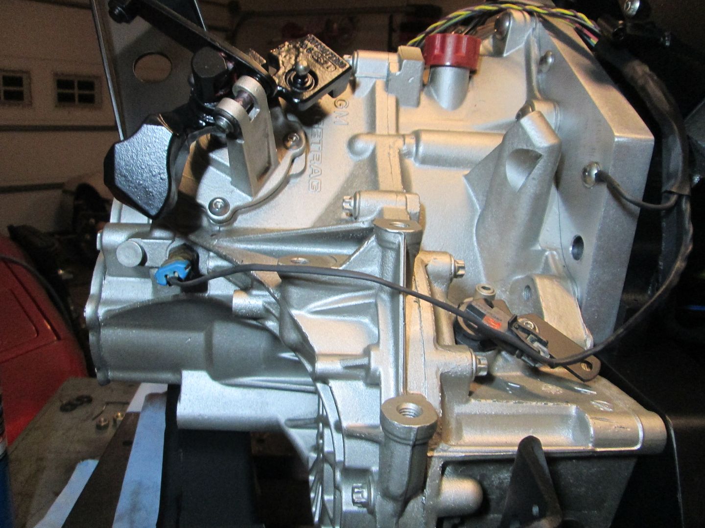
The side of the cradle needed to be notched to allow the transmission (F23 Getrag) to be lowered:
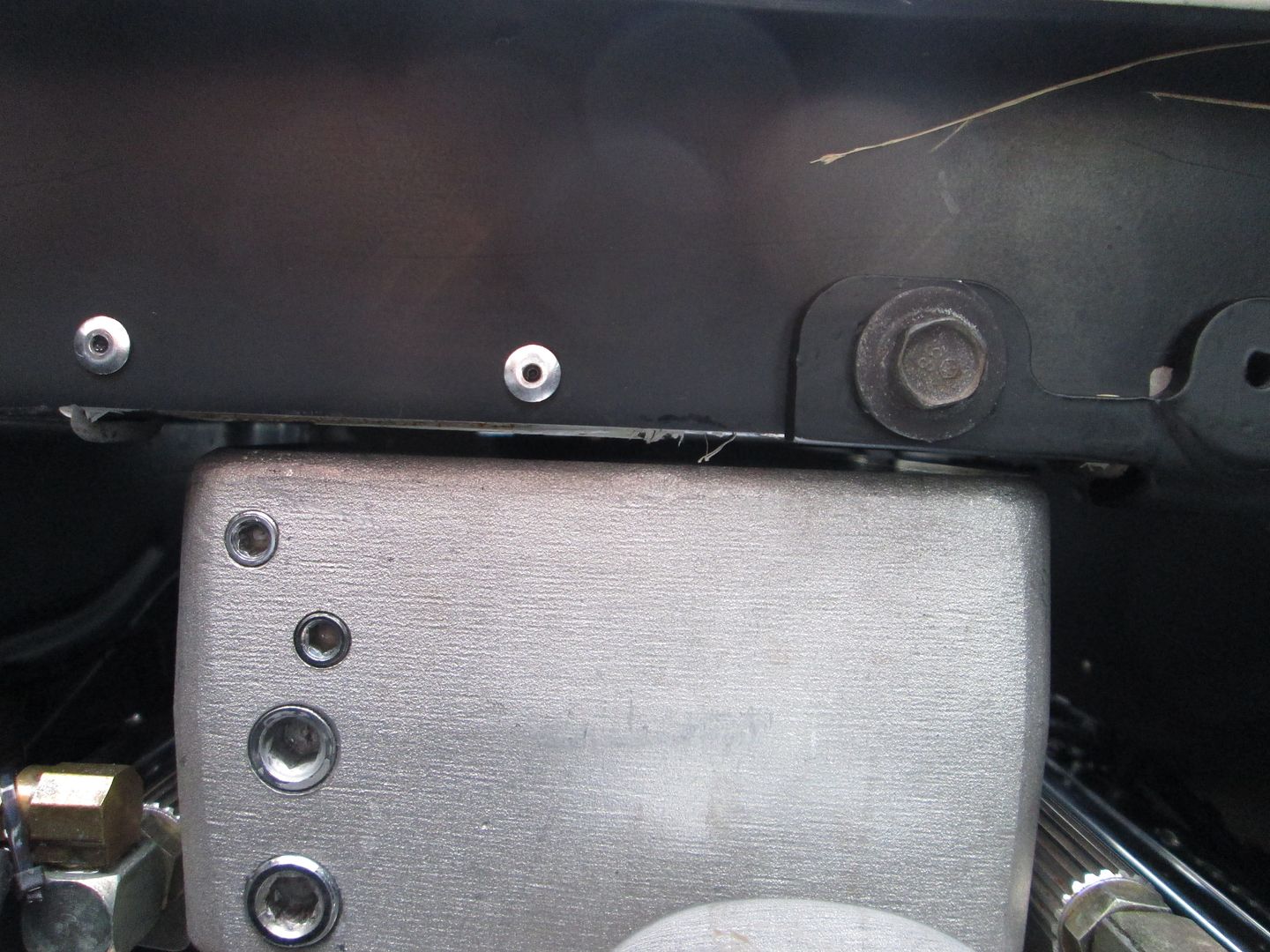
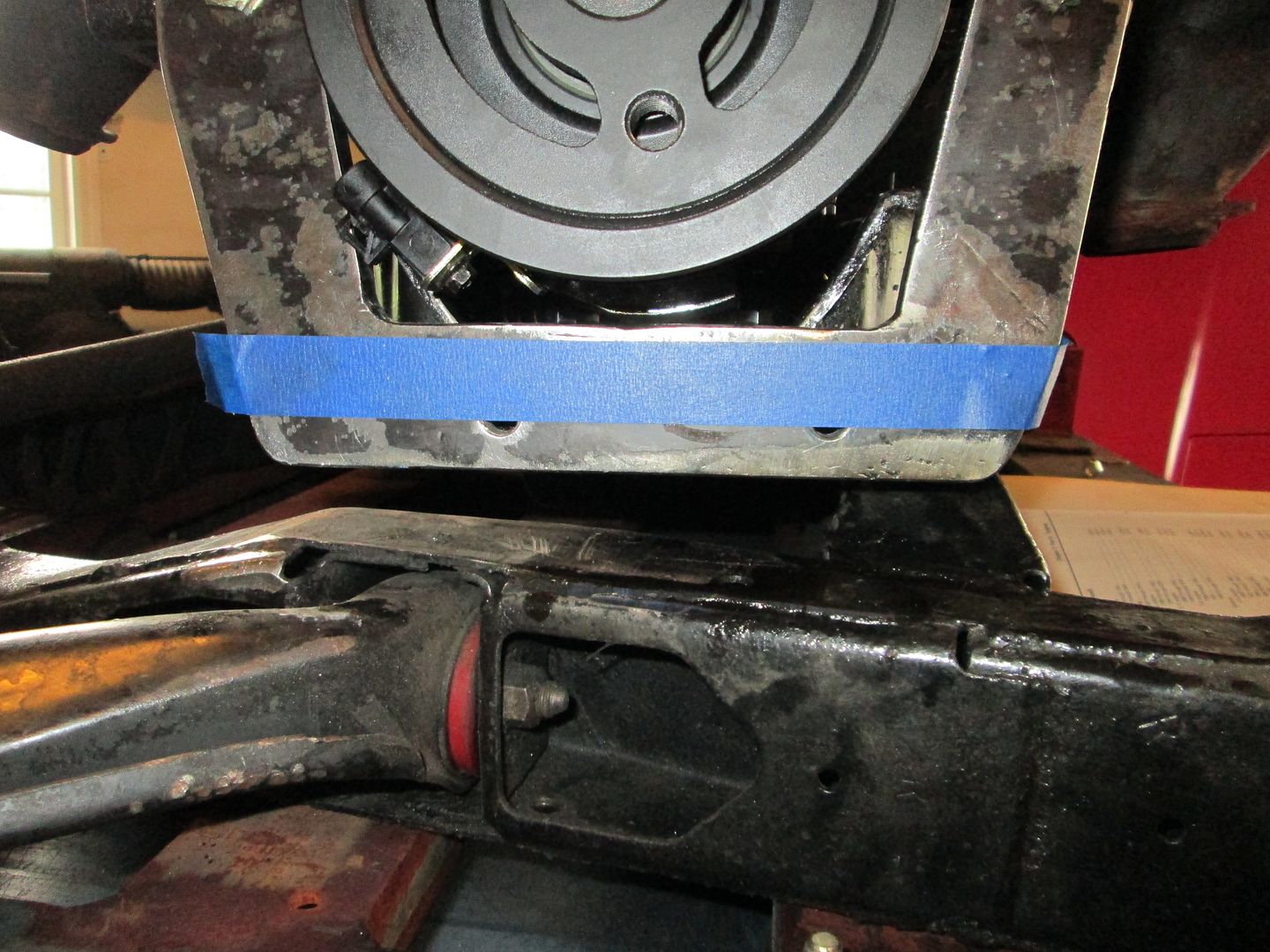
Once this first round of mods were done, it was time to support the drivetrain on the cradle and do another test fit to check for plenum clearance.
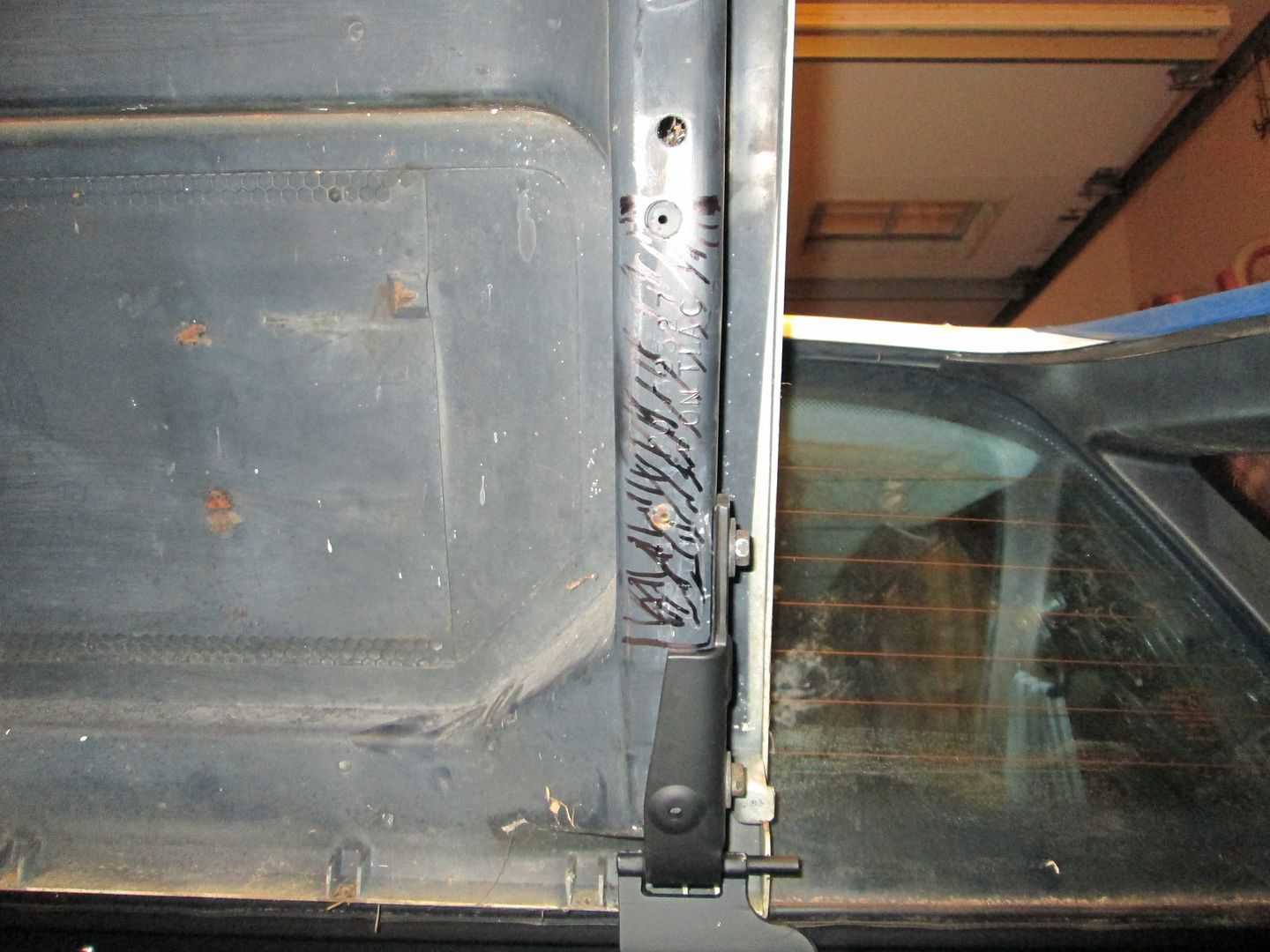
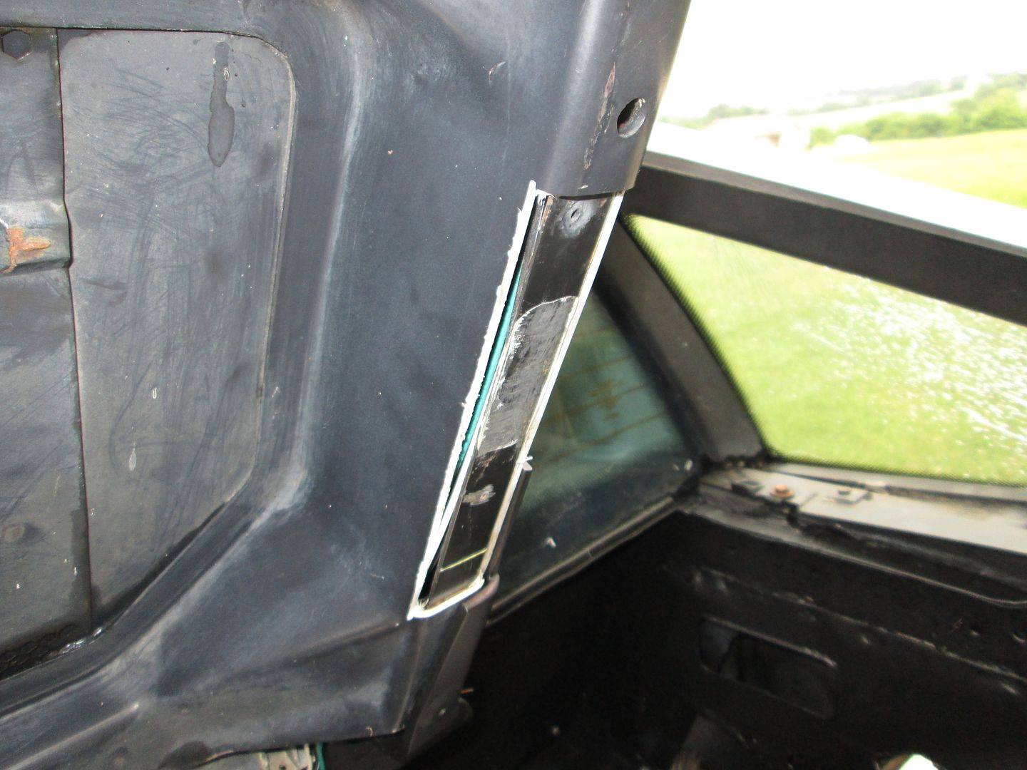
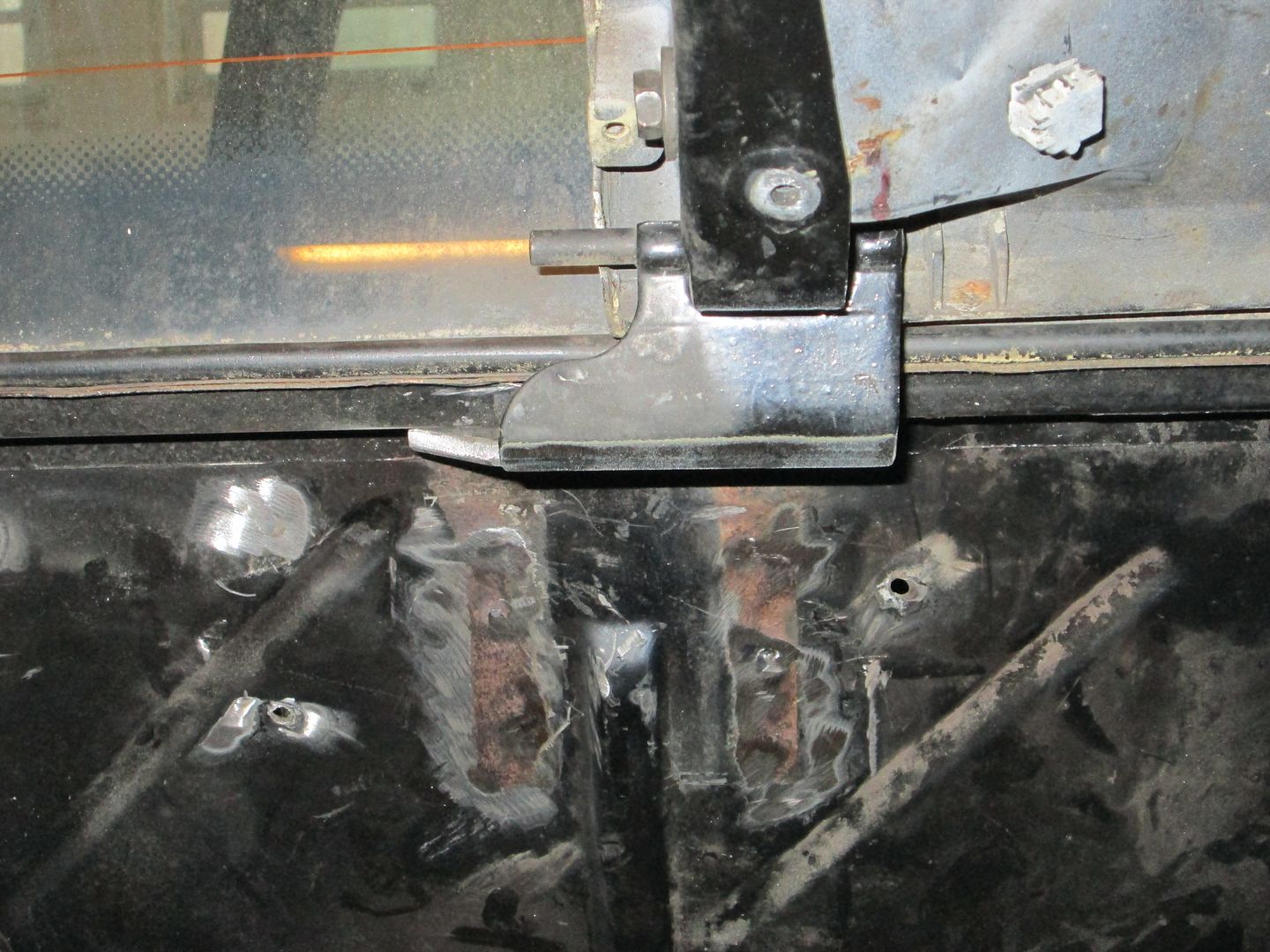
If you look closely at the bolt holes in the hinges, you can see the plenum still does not clear the decklid (decklid is raised up slightly):
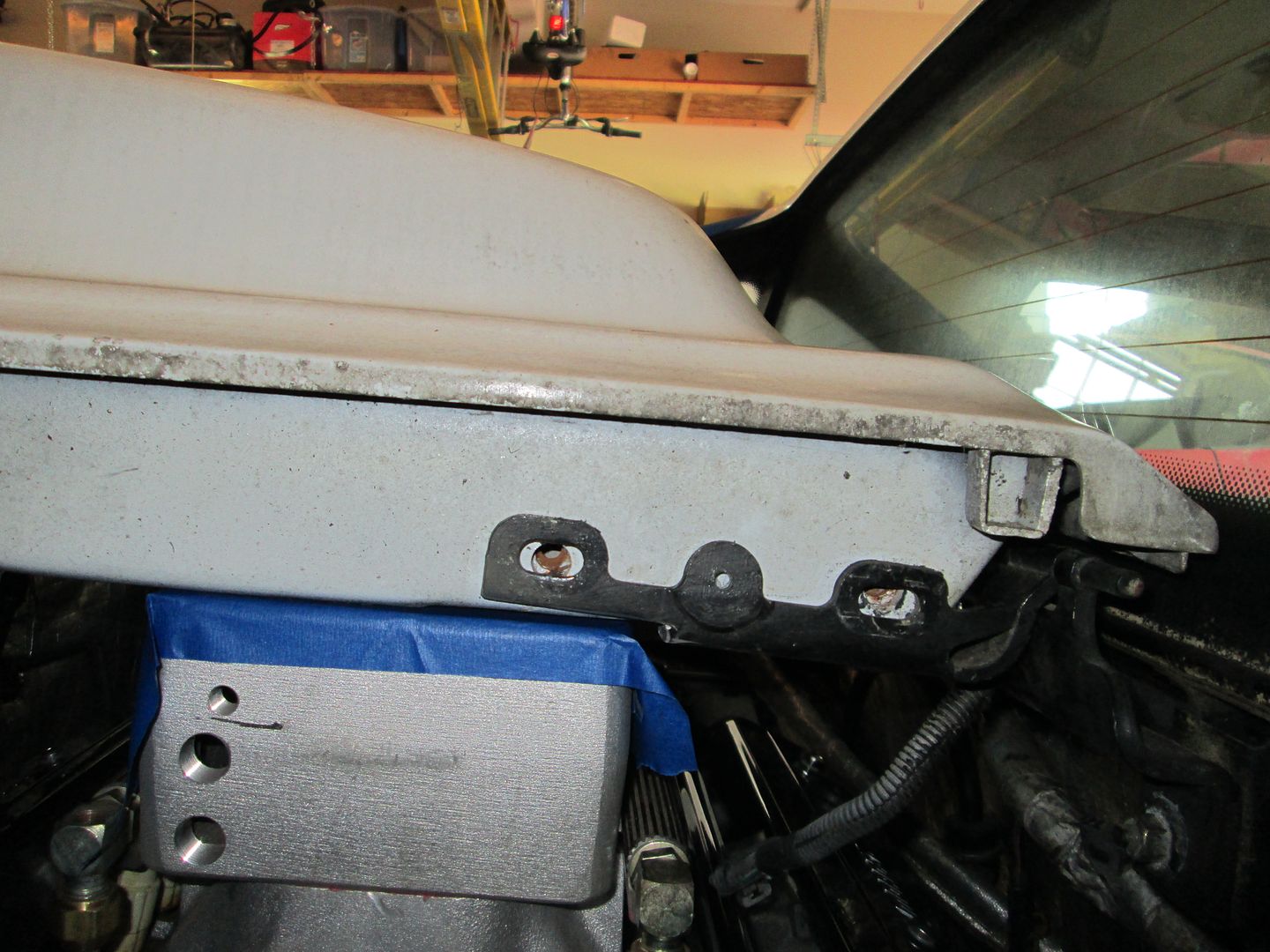
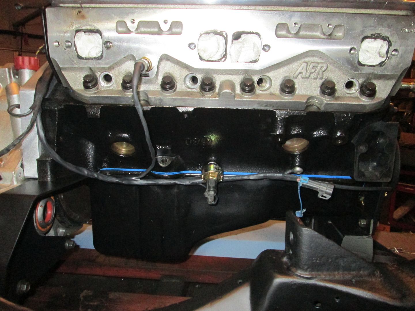
However, the oil pan is pretty much flush with the bottom of the cradle, so the drivetrain can't really go much lower:
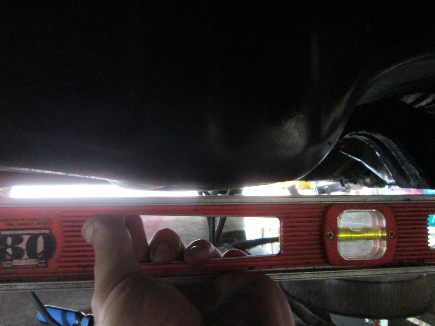
At this point the owner and I decided we both could live with a 1/8" deep notch to the engine decklid... much, much better than the original mockup.
The V8 Archie engine mount needed to have about 1/2" cut off from the bottom:
I drilled 2 new mounting holes at the lower corners, welded up the half holes left from the original mounting holes, and installed it using the lowest set of holes:
The A/C bracket needed a 5th hole drilled into it (the bottom hole) it could be shifted upwards slightly to clear the cradle:
While working on the front engine mounts, I also knocked out the serpentine belt conversion. The V8 Archie kit uses a V-belt. The serpentine balancer used for this swap is from an 89+ FDW 2.5L 4 cylinder. It is a direct bolt on for the SBC and places the belt drive as tight to the timing cover as possible.
It is a tight fit for the crankshaft sensor between the front engine mount and the balancer. You can also see how close the balancer is to the L31 timing cover:
The rest of the serpentine conversion requires swapping the pulleys on the AC compressor and alternator. Then notching the V8 Archie alternator mount for a 3.1L Camaro belt tensioner and using an existing hole to mount the other idler pulley. Once done is will look something like this:
Moving on to the other side of the drivetrain, the lower edge of the V8 Archie adapter plate needed to be trimmed down further:
The side of the cradle needed to be notched to allow the transmission (F23 Getrag) to be lowered:
Once this first round of mods were done, it was time to support the drivetrain on the cradle and do another test fit to check for plenum clearance.
If you look closely at the bolt holes in the hinges, you can see the plenum still does not clear the decklid (decklid is raised up slightly):
However, the oil pan is pretty much flush with the bottom of the cradle, so the drivetrain can't really go much lower:
At this point the owner and I decided we both could live with a 1/8" deep notch to the engine decklid... much, much better than the original mockup.
06-14-2014, 05:52 PM
#3
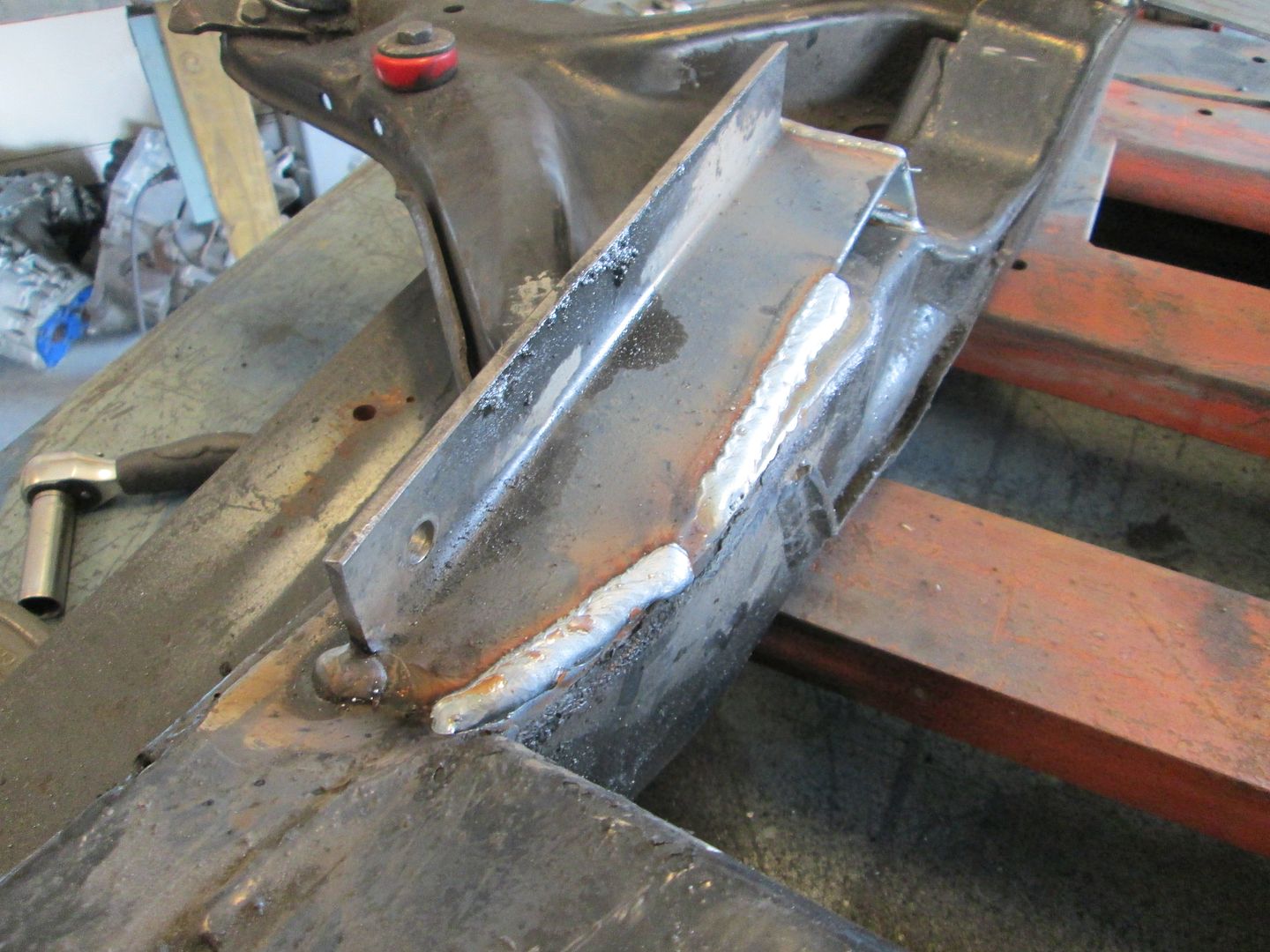
Now that the drivetrain height was set, it was time to fabricate new transmission mounts.
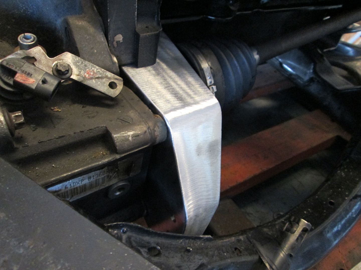
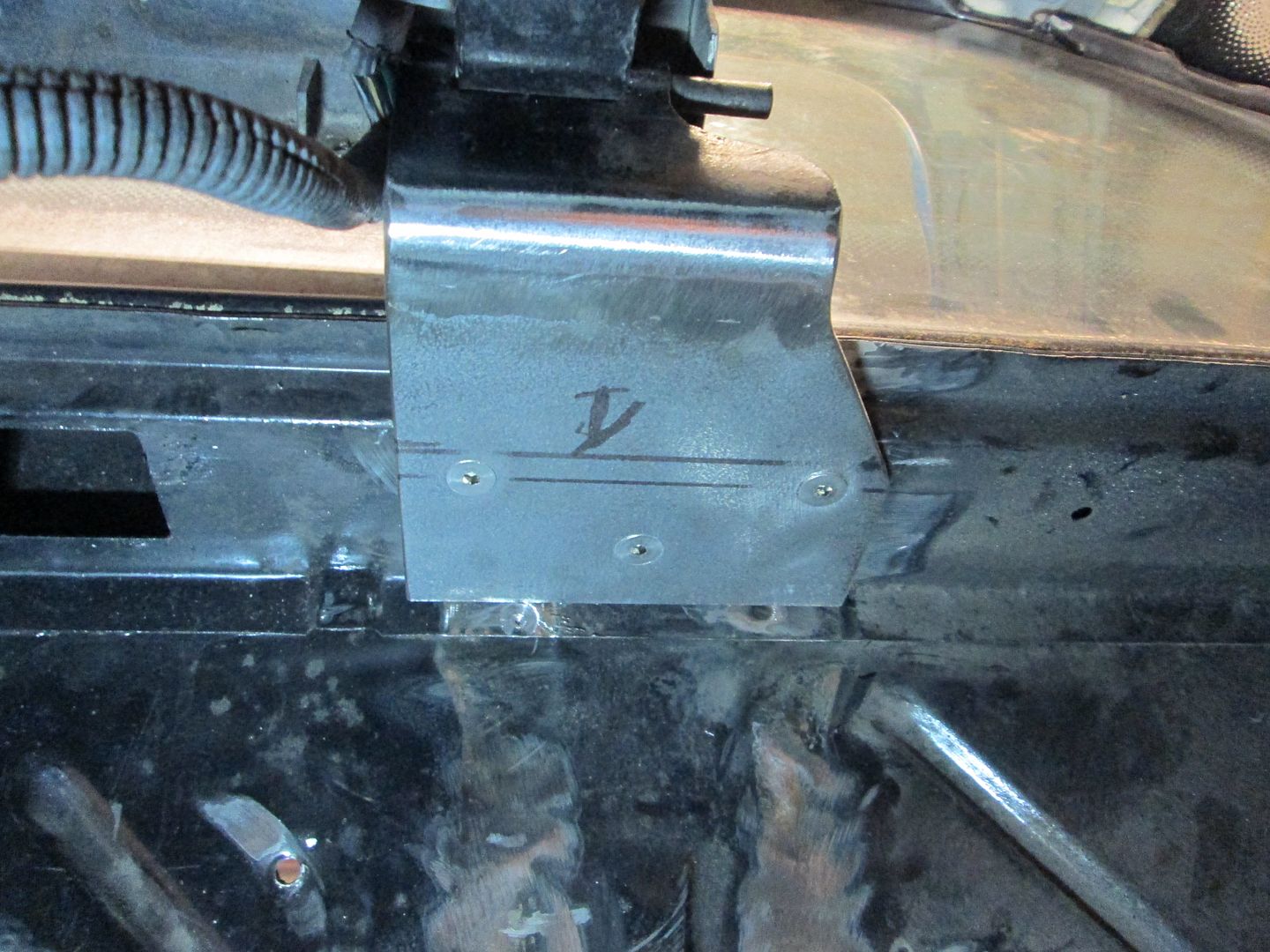
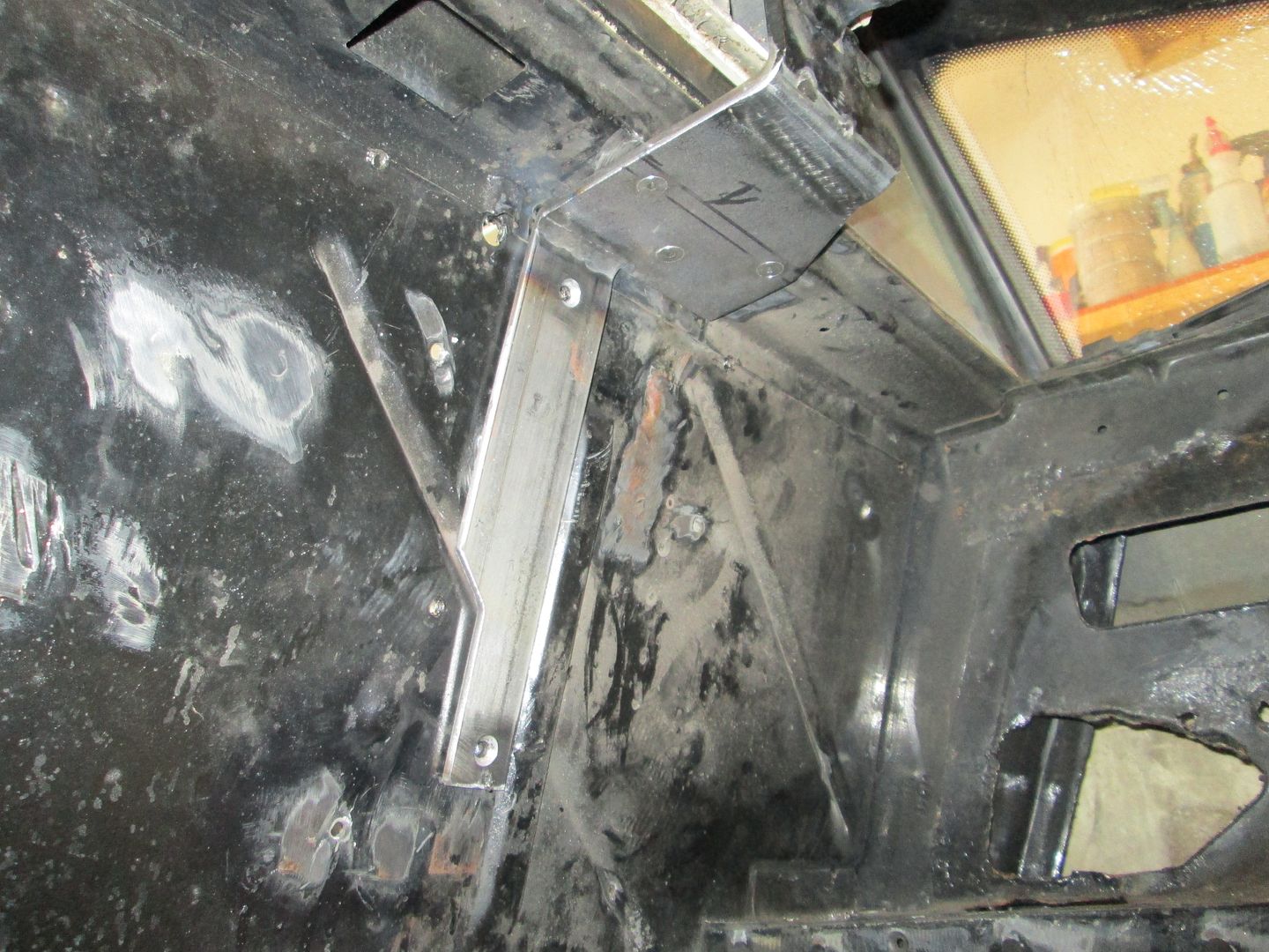
The front transmission mount was fabbed up using some tubes and cutting/bending some mild steel. Here is the backside of the mount:
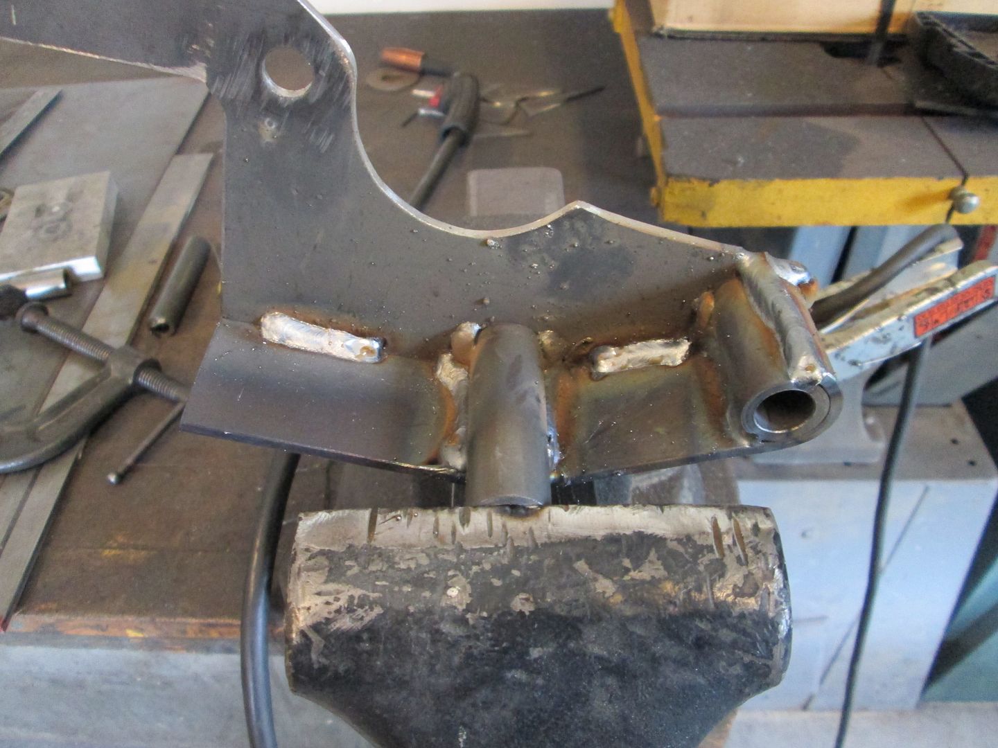
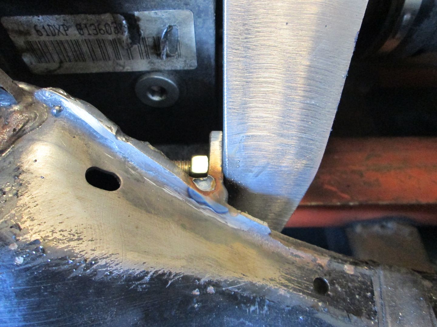
Here is the visible side. This will be welded solid to the cradle:
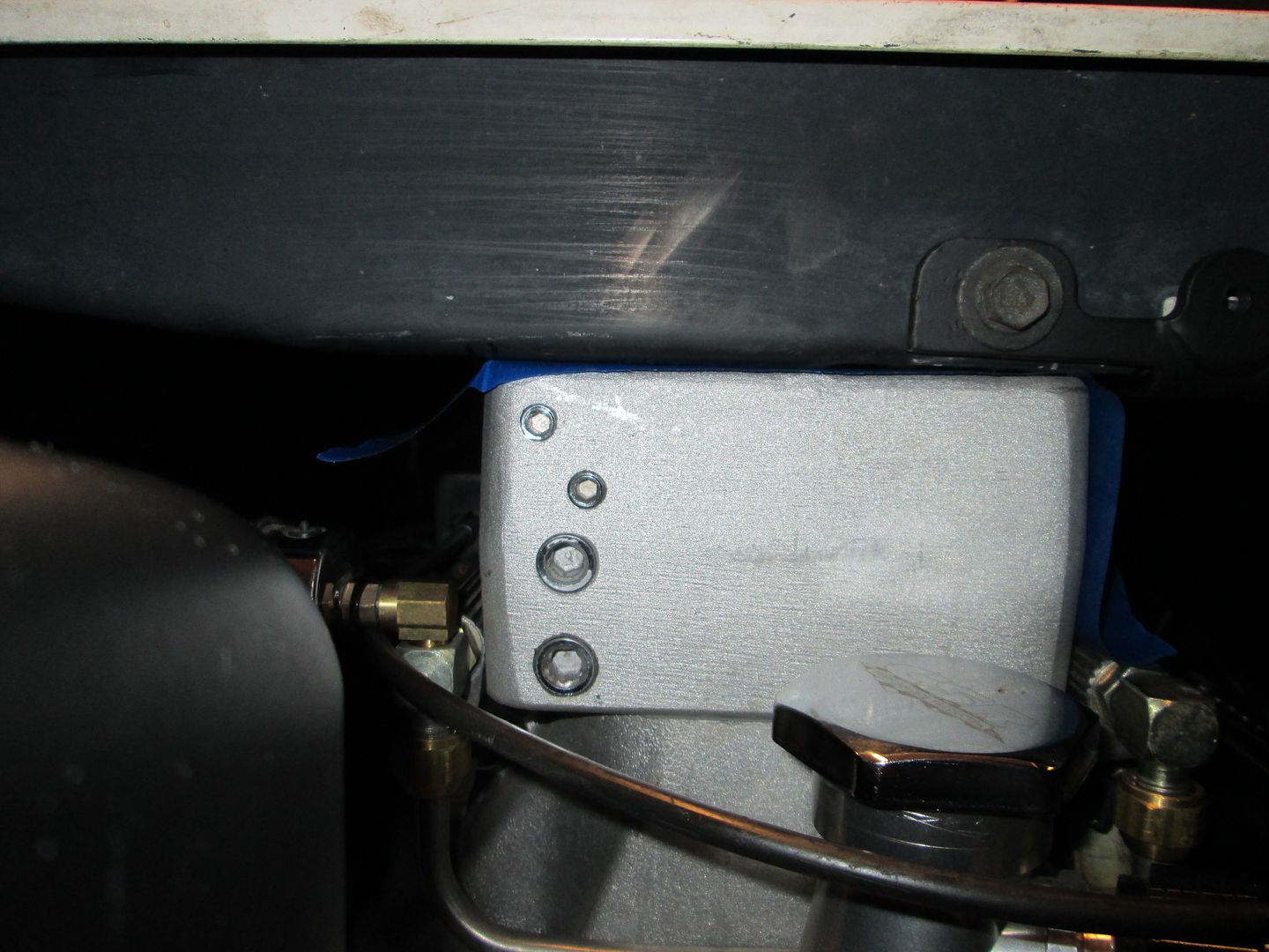
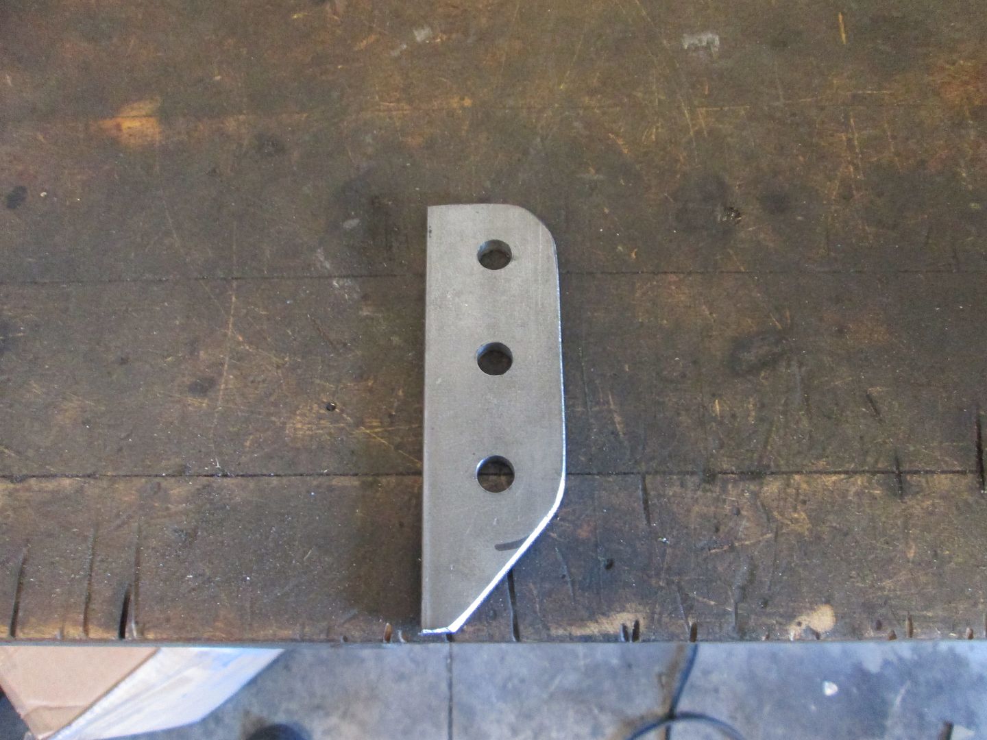
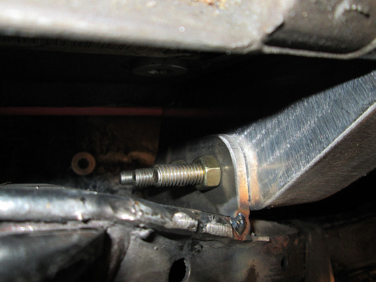
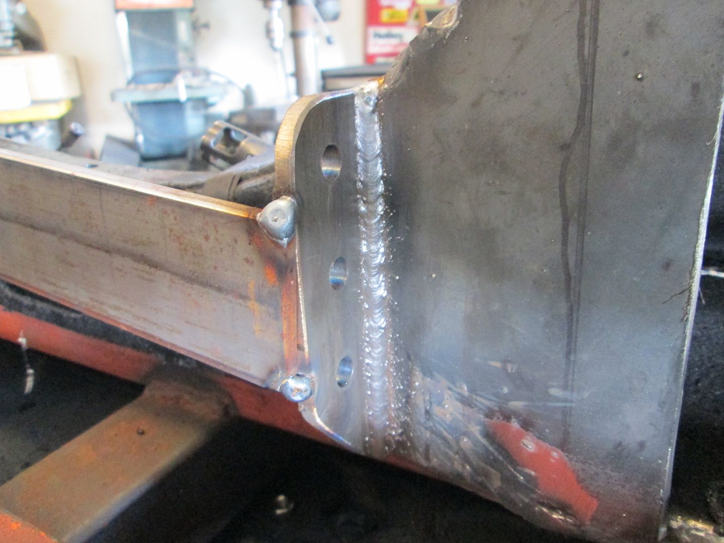
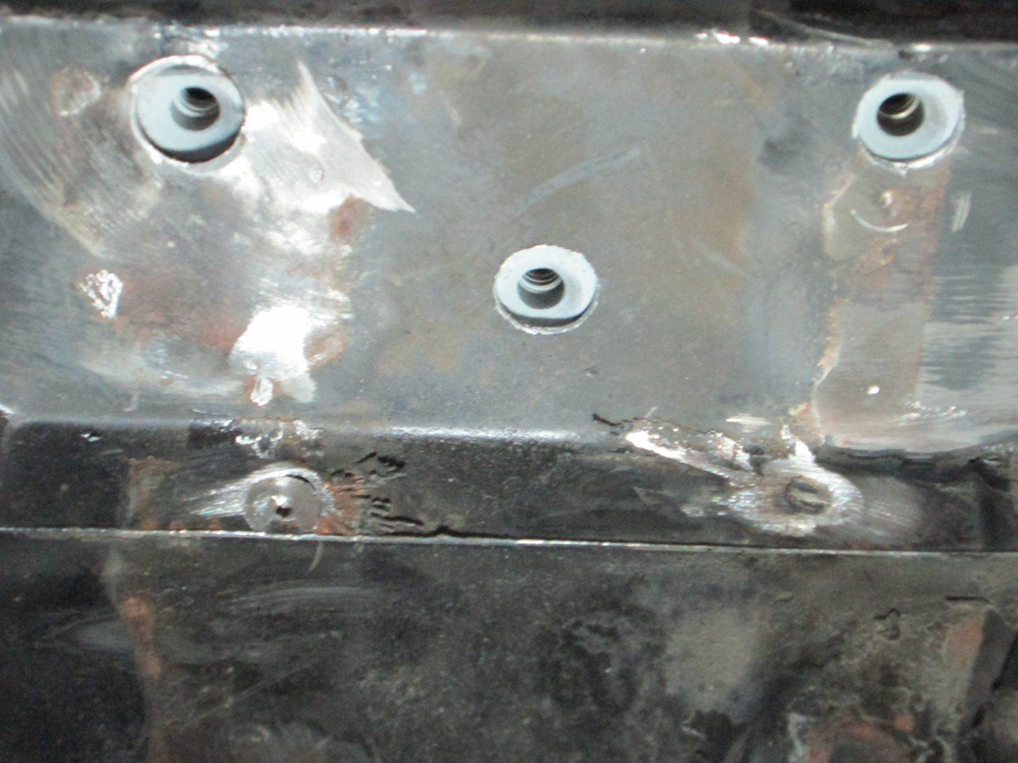
The rear transmission mount is also made from 1/8" steel and comes off the SBC starter pad as well as several bolt holes on the transmission differential:
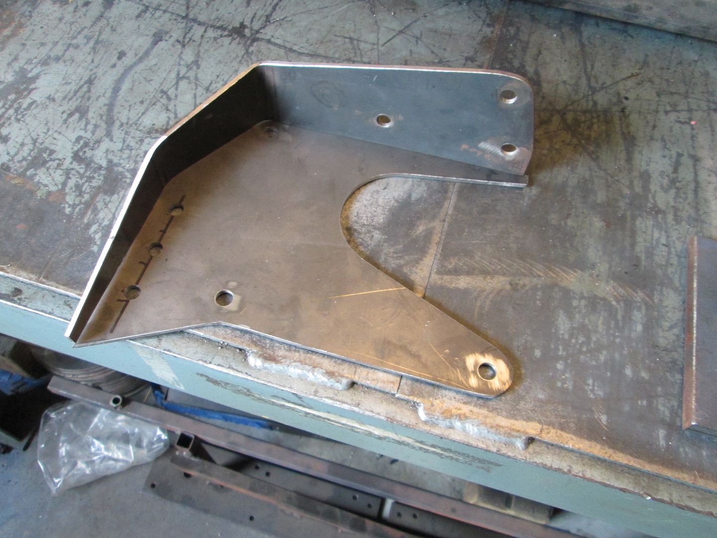
This plat was welded to the cradle and the rear transmission mount bolts to it with three 3/8" bolts:
I will post more in the next day or two.
The front transmission mount was fabbed up using some tubes and cutting/bending some mild steel. Here is the backside of the mount:
Here is the visible side. This will be welded solid to the cradle:
The rear transmission mount is also made from 1/8" steel and comes off the SBC starter pad as well as several bolt holes on the transmission differential:
This plat was welded to the cradle and the rear transmission mount bolts to it with three 3/8" bolts:
I will post more in the next day or two.
06-15-2014, 01:22 PM
#4
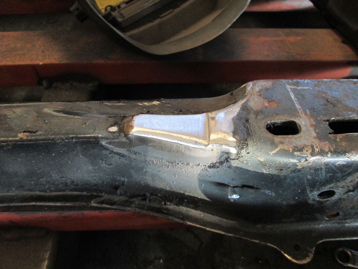
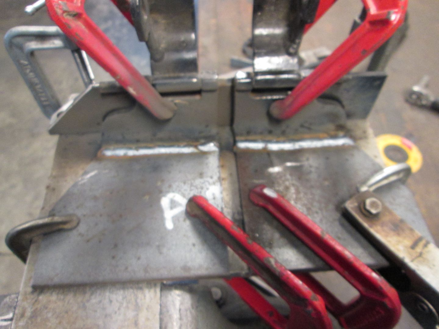
With the mounting system all figured out and fabbed up, it was time to cap all the notched areas of the cradle and do all the finish welding to the mounts:
Notched for the adapter plate and starter mount:
Notched for the transmission:
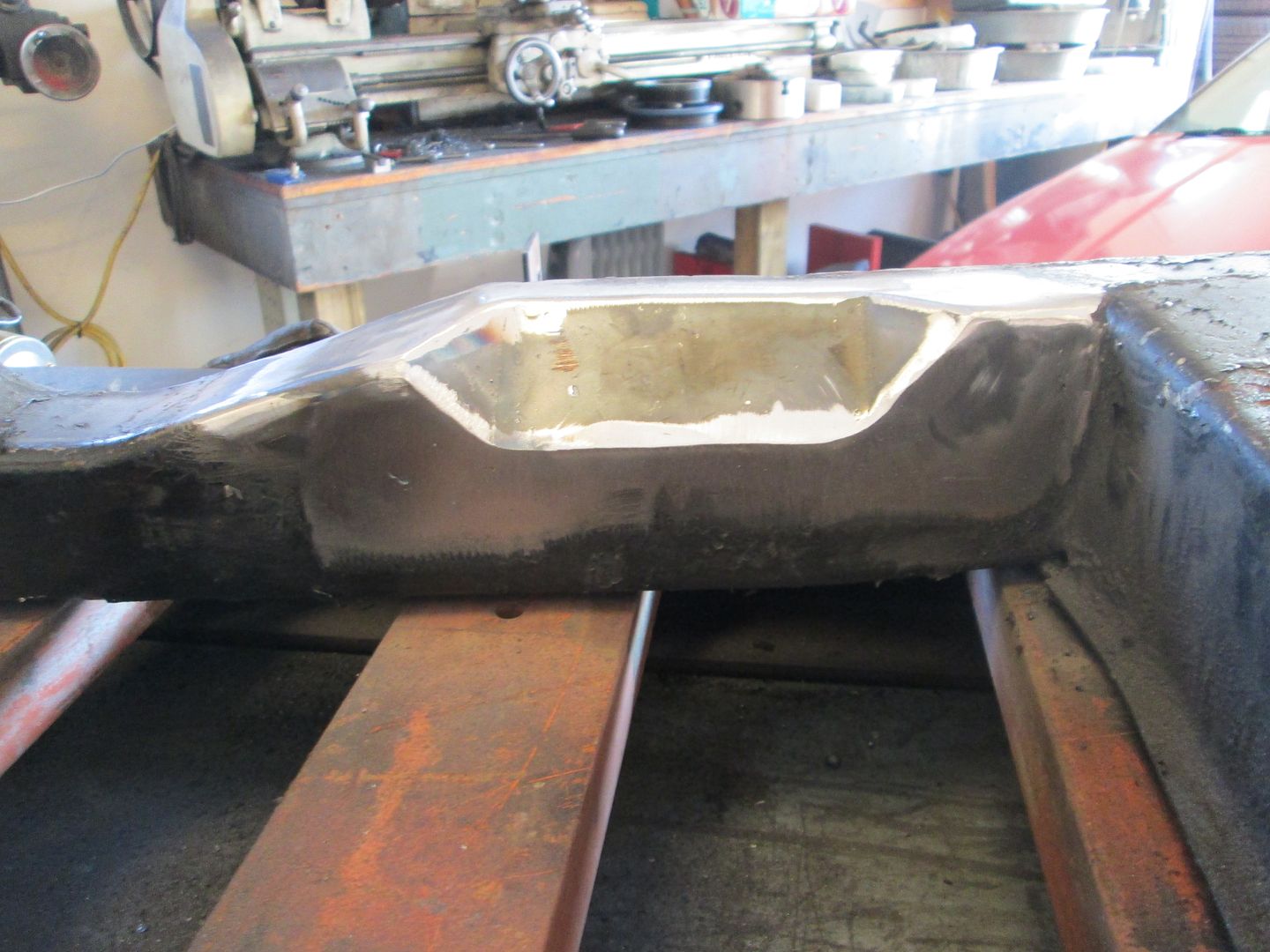
Filled in the original opening for the stock fiero transmission mount:
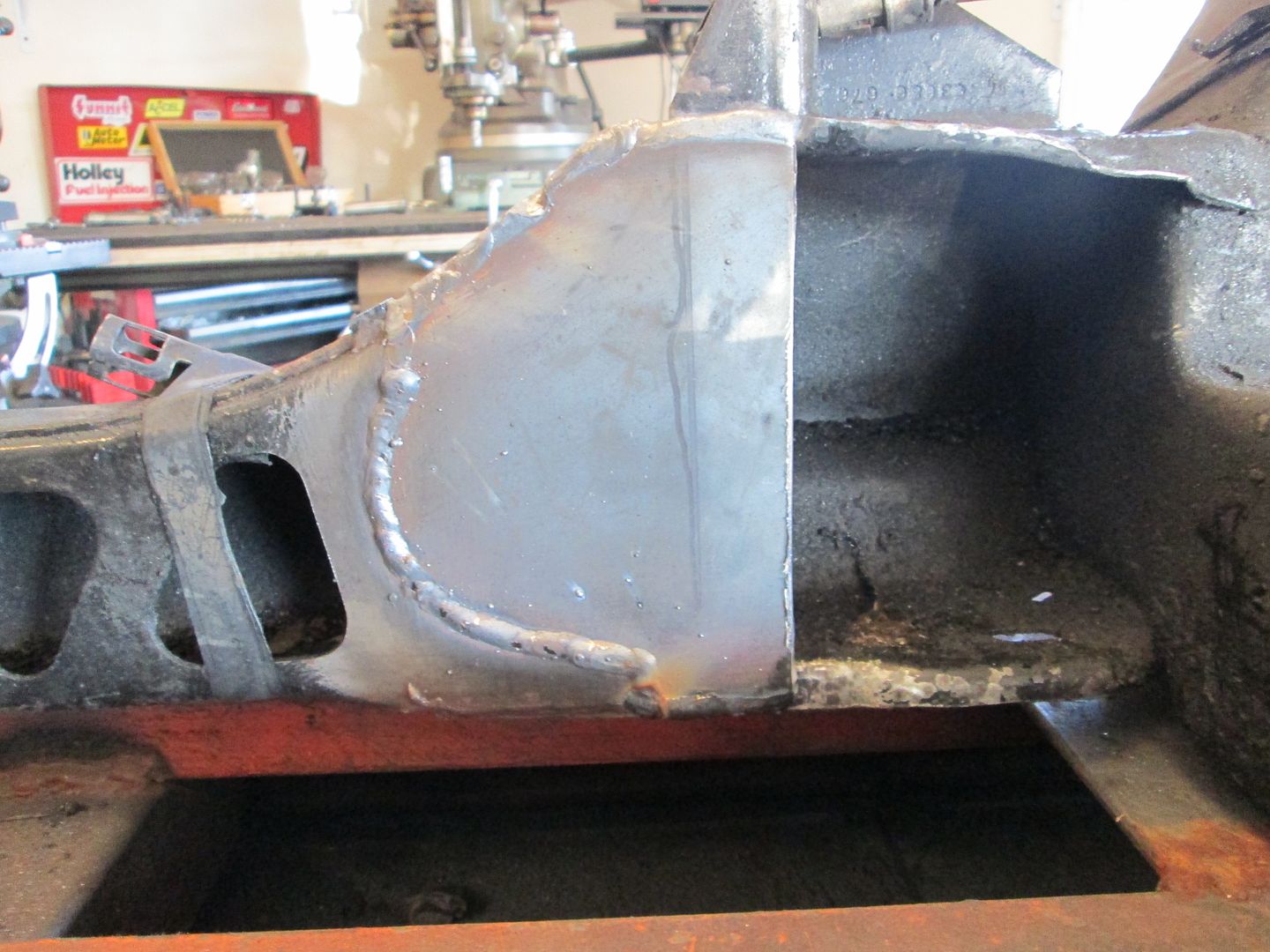
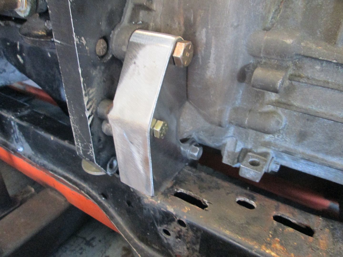
Base for the front engine mount welded into place:
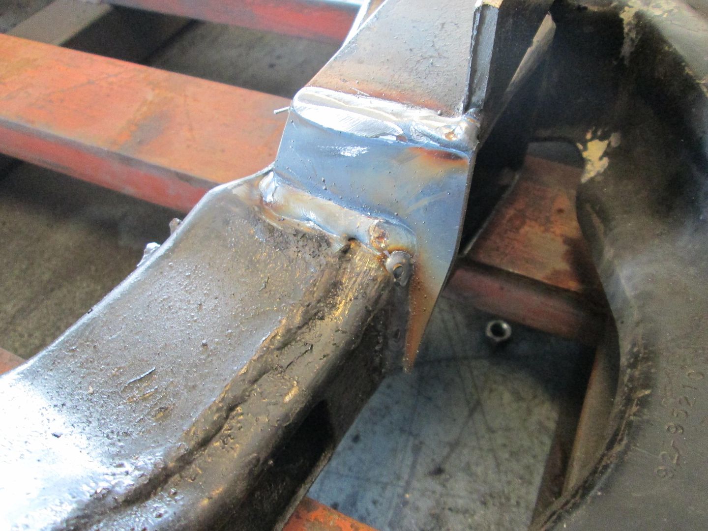
Front transmission mount welded into place:
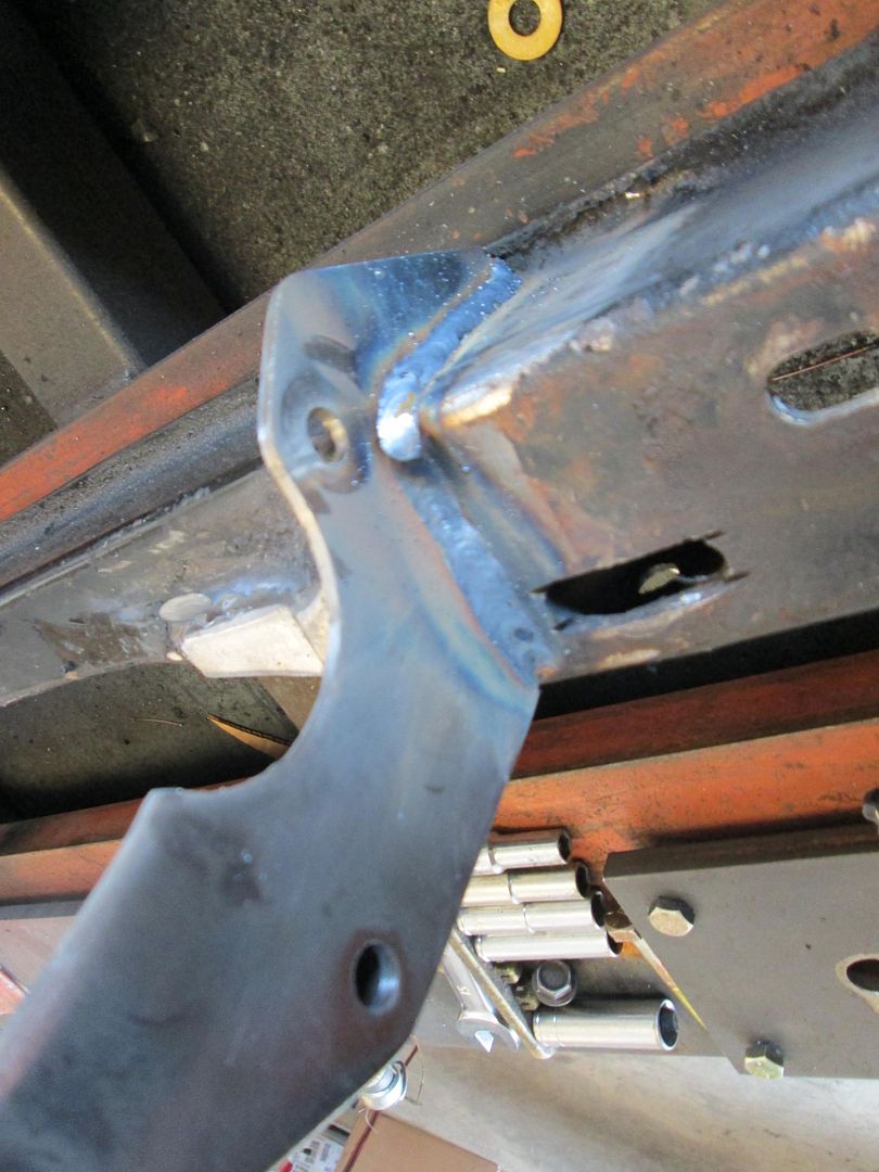
Rear transmission mount tab welded into place:
Notched for the adapter plate and starter mount:
Notched for the transmission:
Filled in the original opening for the stock fiero transmission mount:
Base for the front engine mount welded into place:
Front transmission mount welded into place:
Rear transmission mount tab welded into place:
06-15-2014, 01:53 PM
#5
Once the mounts were done, I went back and installed the EFI connection 24X conversion kit. Here are the main parts (except the L31 timing cover)

First step was removing the cover and sliding the reluctor wheel into place and checking its depth to the supplied spec:
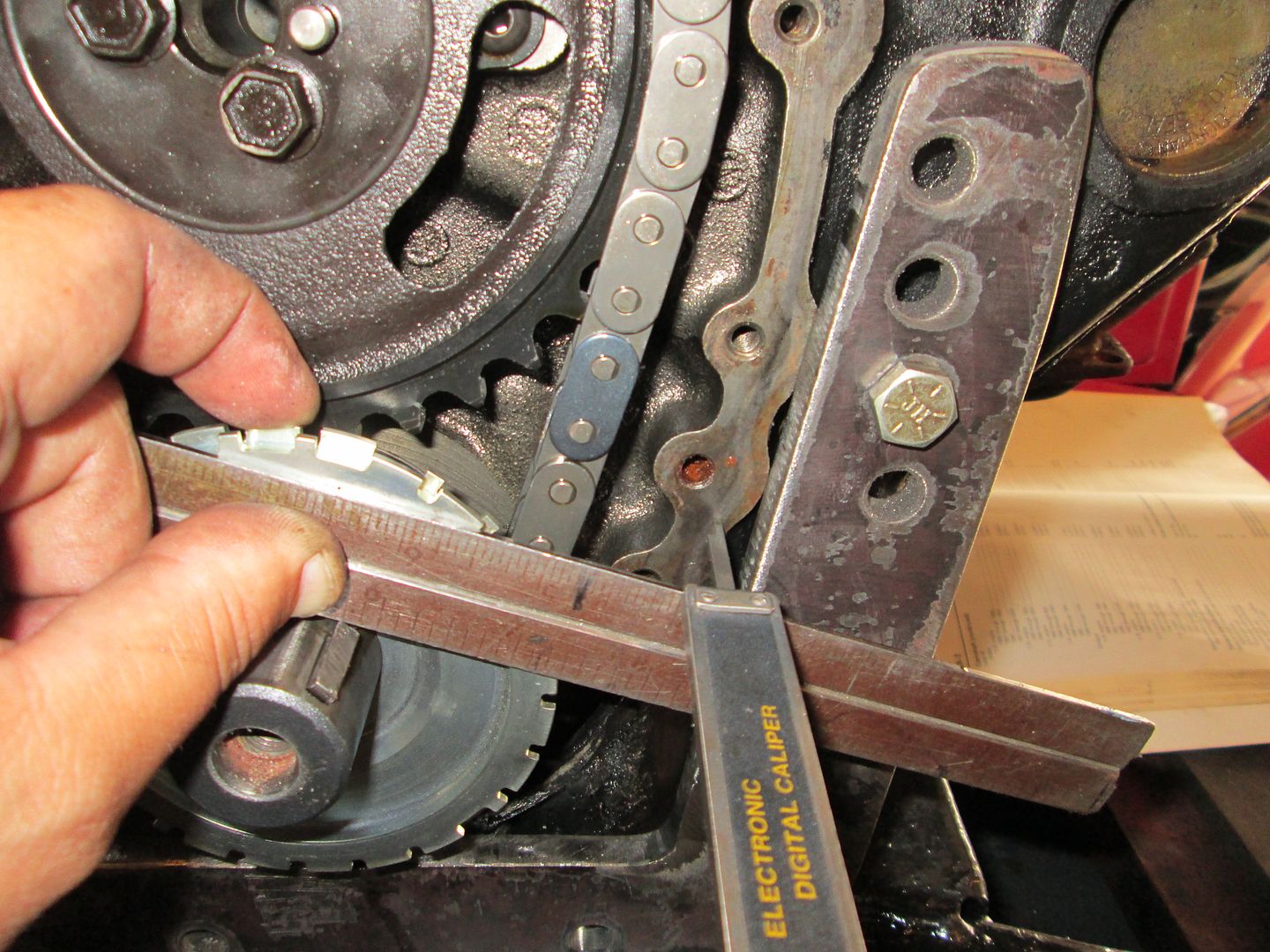
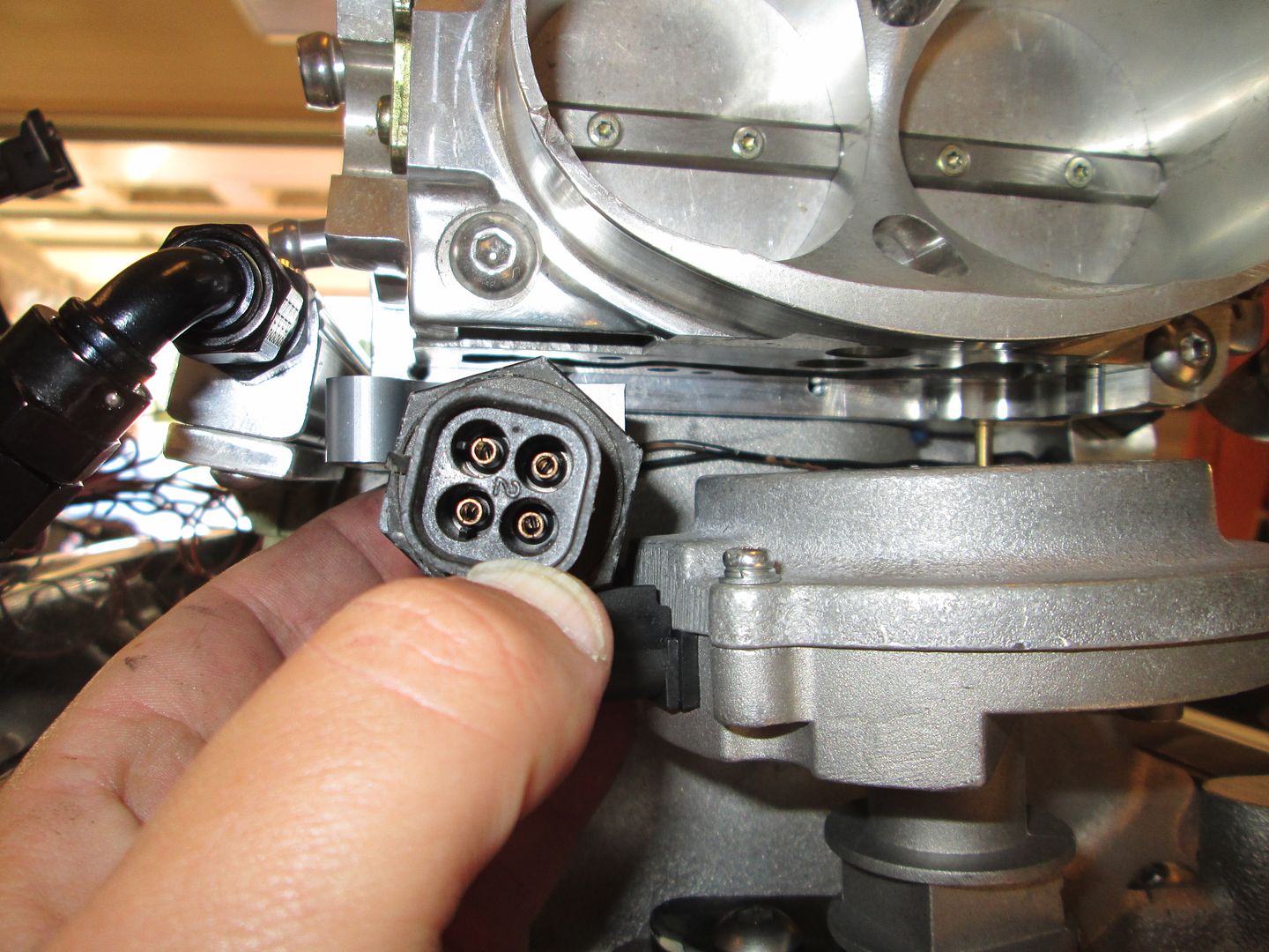
The next step is to install the distributor and make sure it is lined up properly.

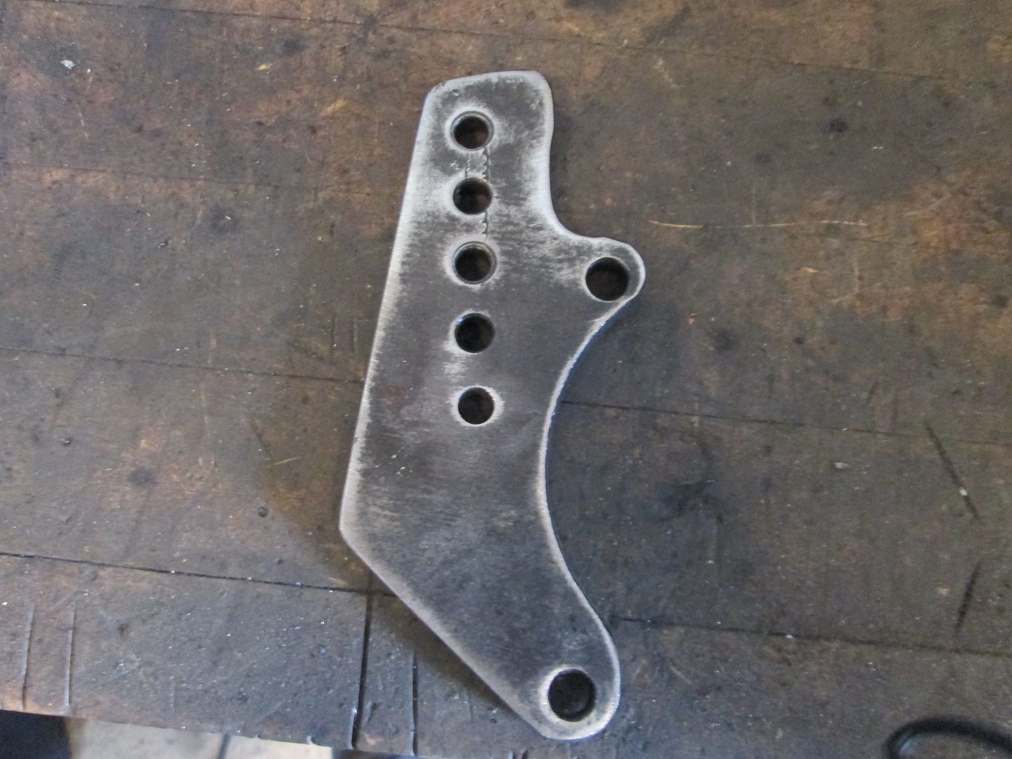
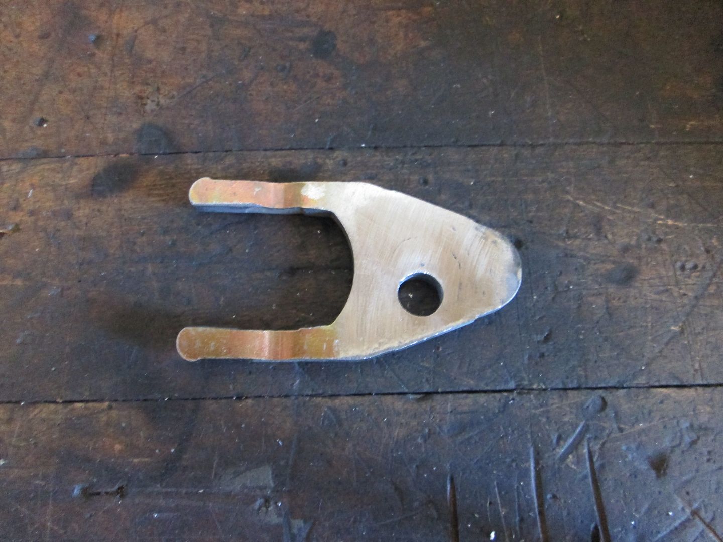
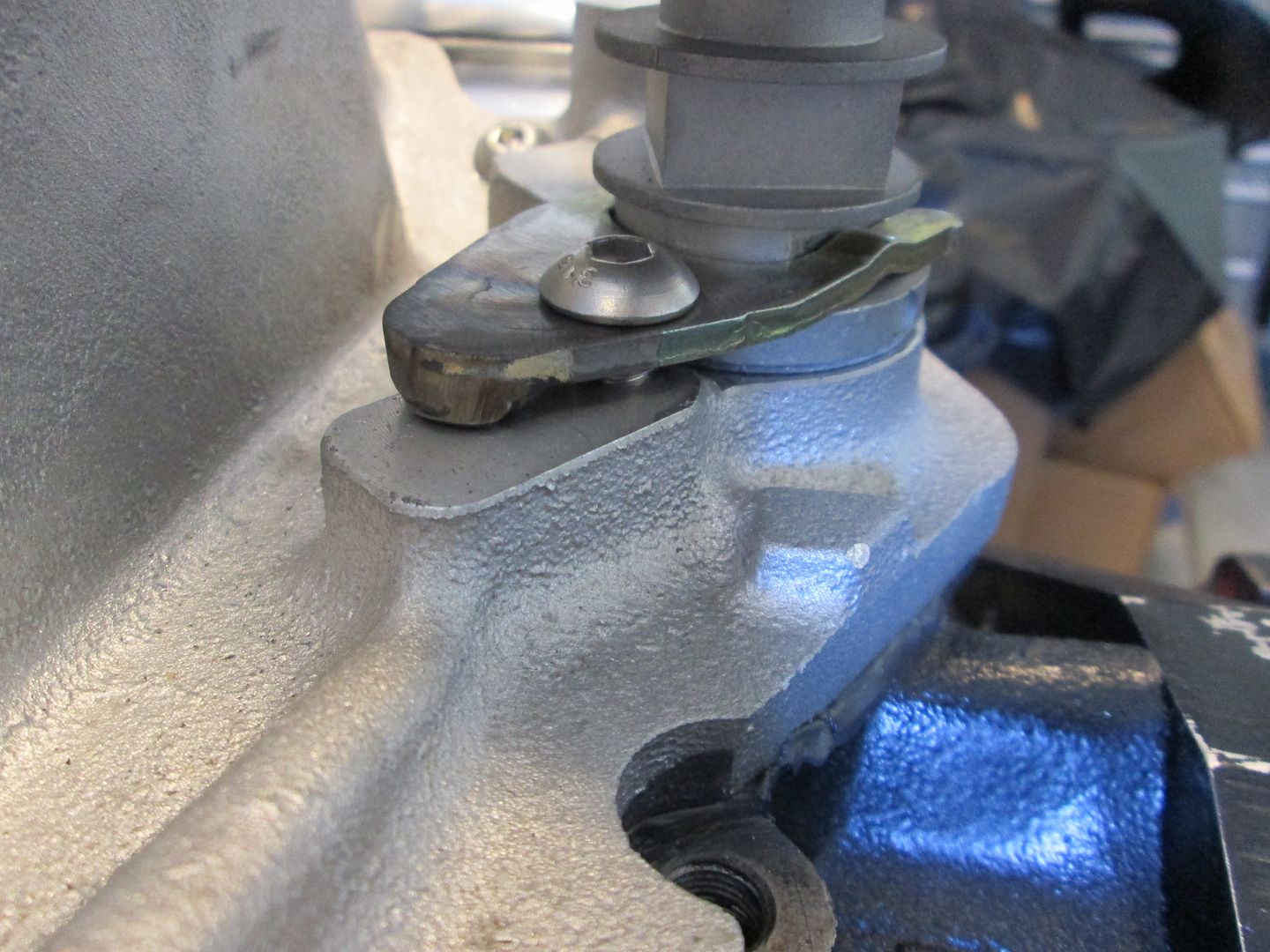
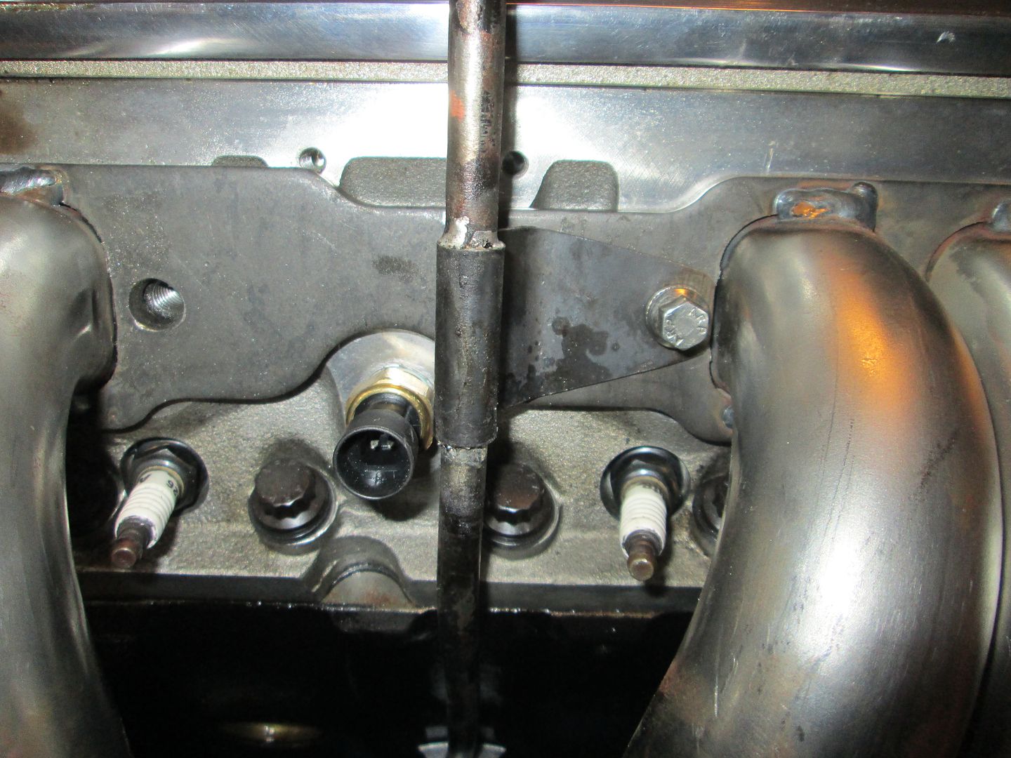
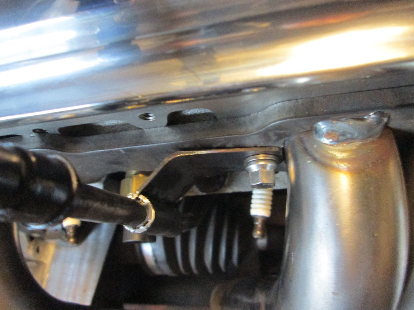
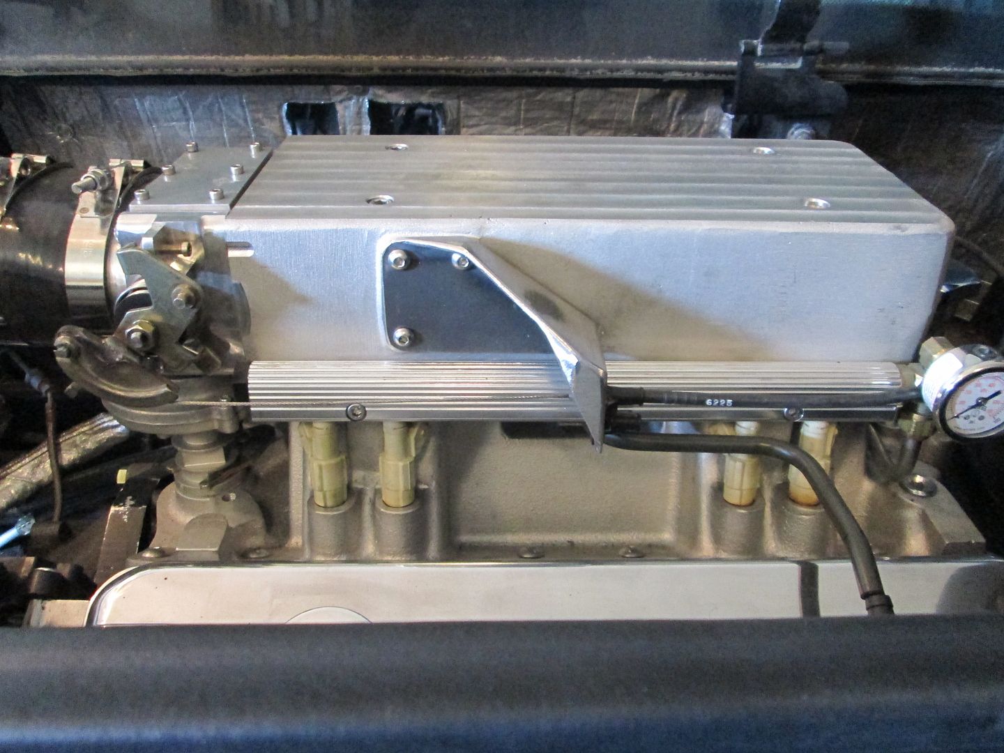
I had clocked the distributor housing so the cam sensor connector would point towards the front of the engine bay and be hidden, so I had to rework the supplied dist hold down bracket to work. I move the hole and added a support shelf to it:
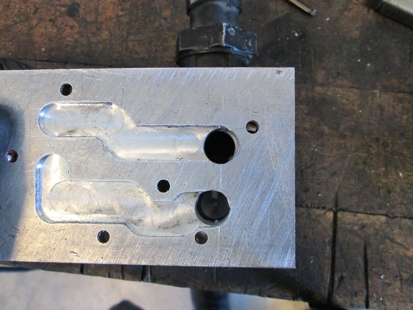
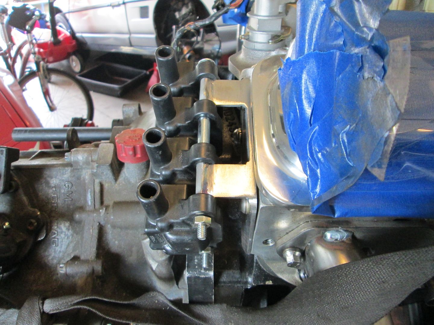
I wanted to flip the plenum 180 so the throttle body would be over the transmission (Fiero style). The modifications to make the overall intake height shorter, didn't leave any room for the stock IAC housing to fit between the bottom of the TB and the distributor cover:
There was enough room for some 3/8" aluminum plate to fit, so I machined the bottom of the TB housing and machined passages into the plate to create new IAC passages. Then the IAC could bolt to the plate.
Then the intake, plenum and TB were mocked up to see if I could reverse the intake and still clear the distributor cover.
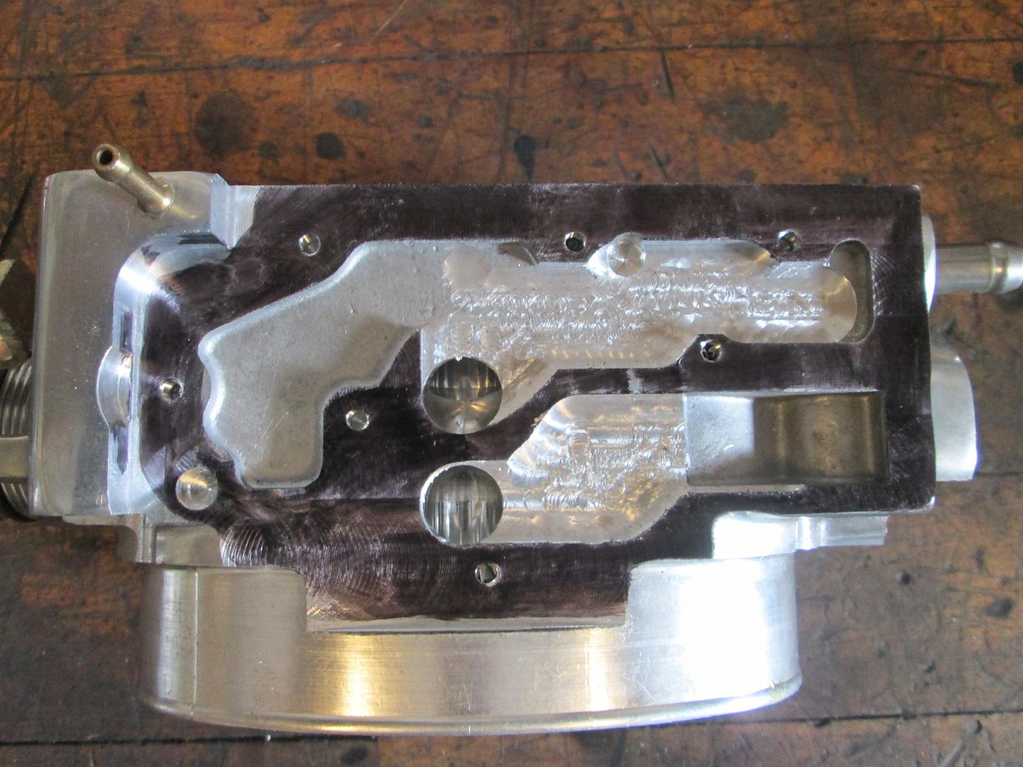
Stock bottom of the TB:
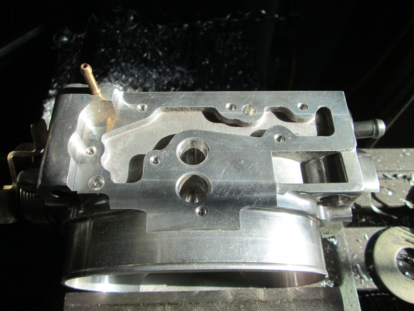
Post IAC passage machining - the sealing flange is black:
The aluminum plate with the same IAC passages machined into it as well as the holes to acces the stock IAC housing:
IAC housing mounted to the new offset plate:
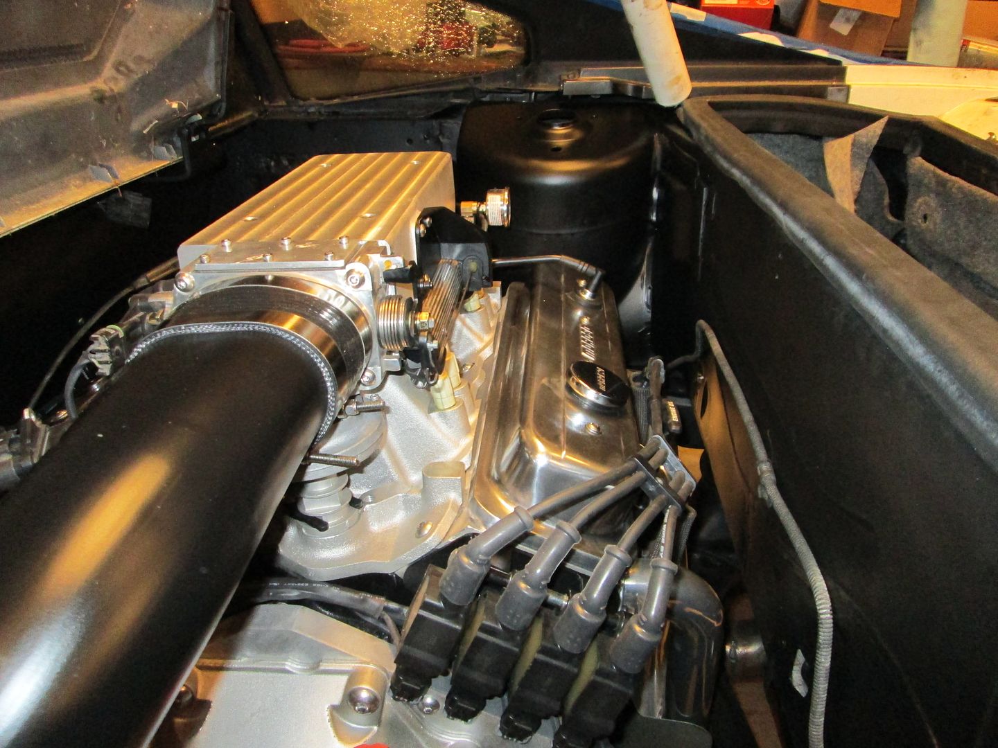
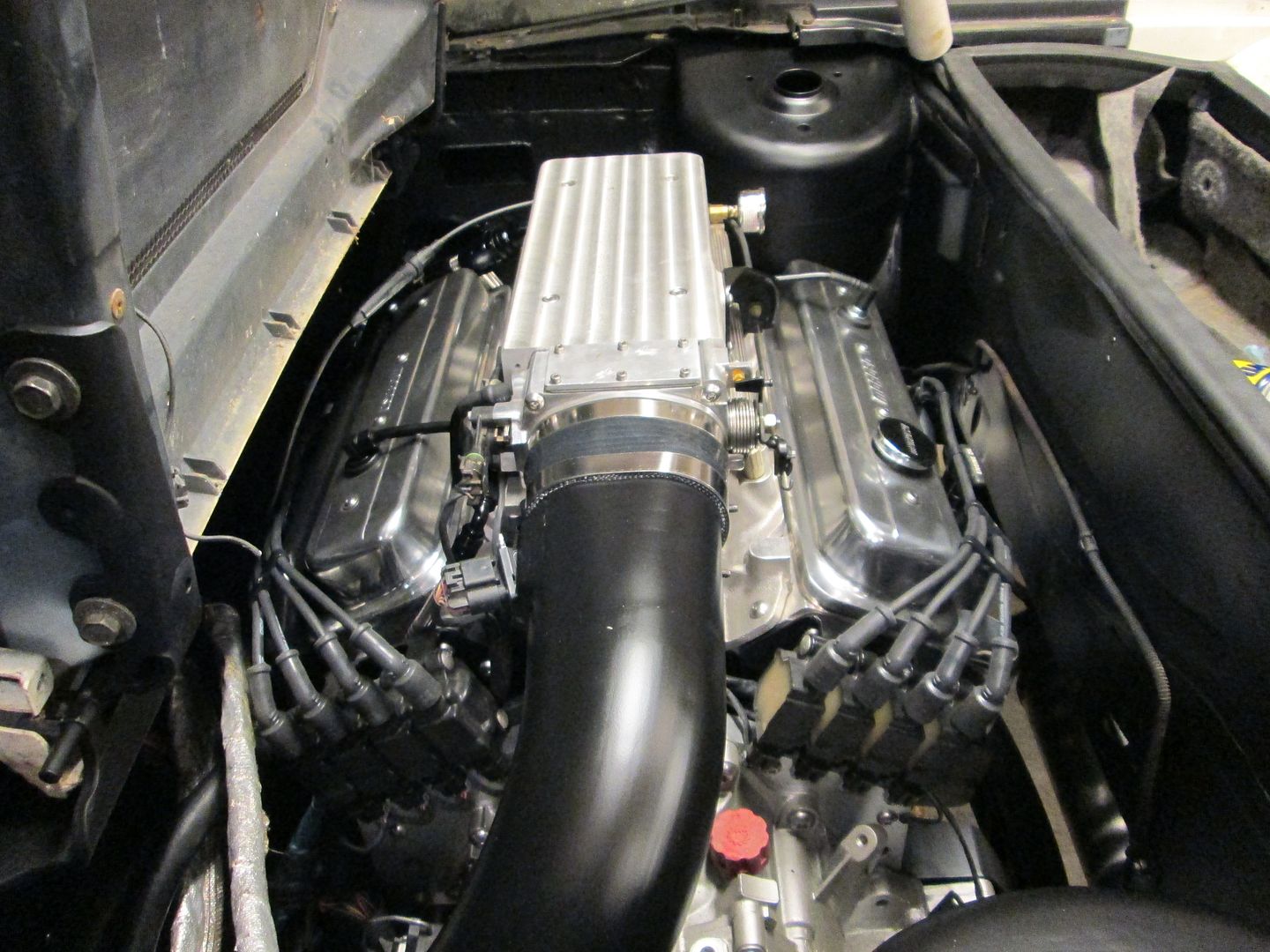
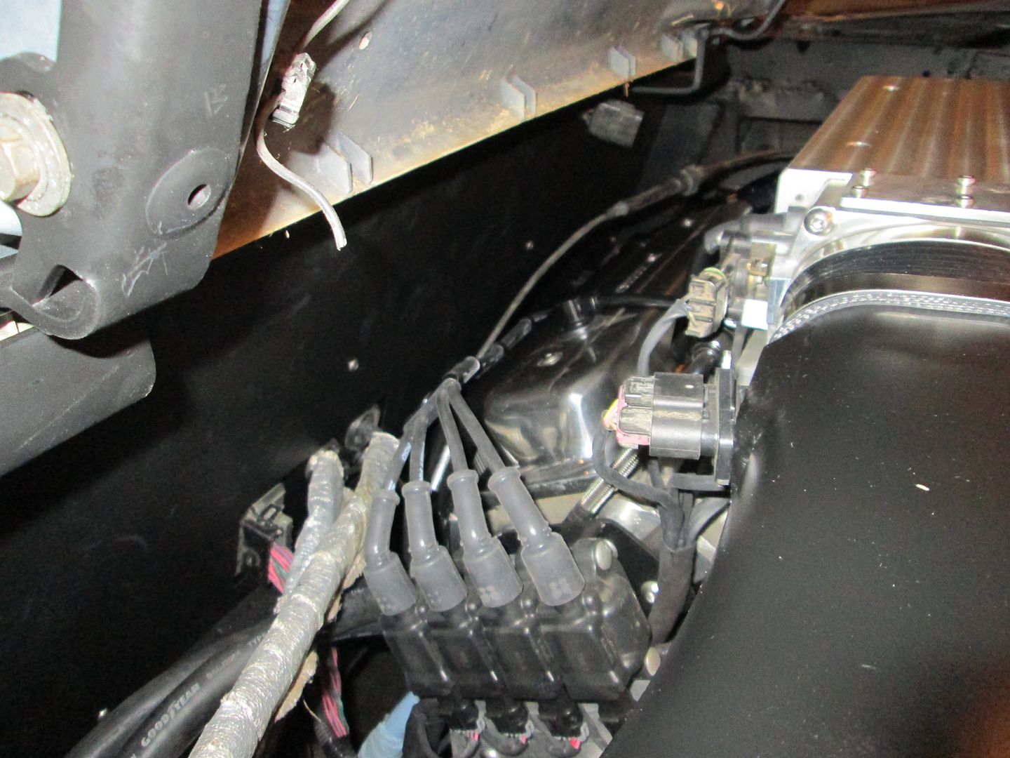
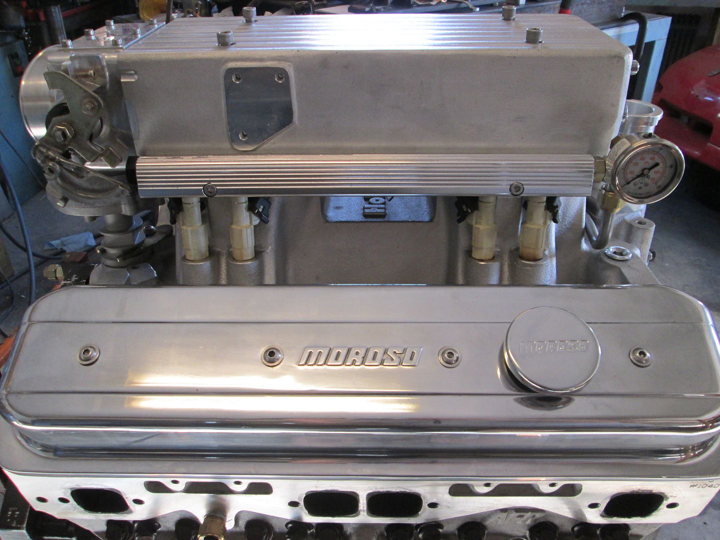
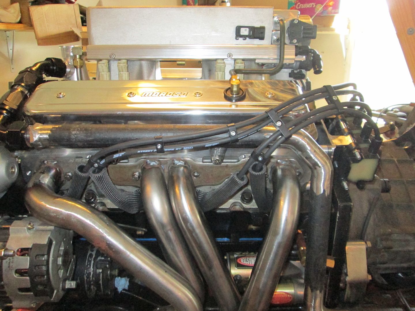
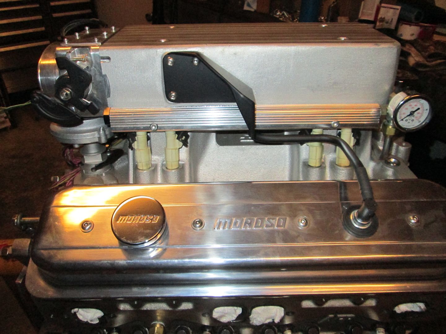
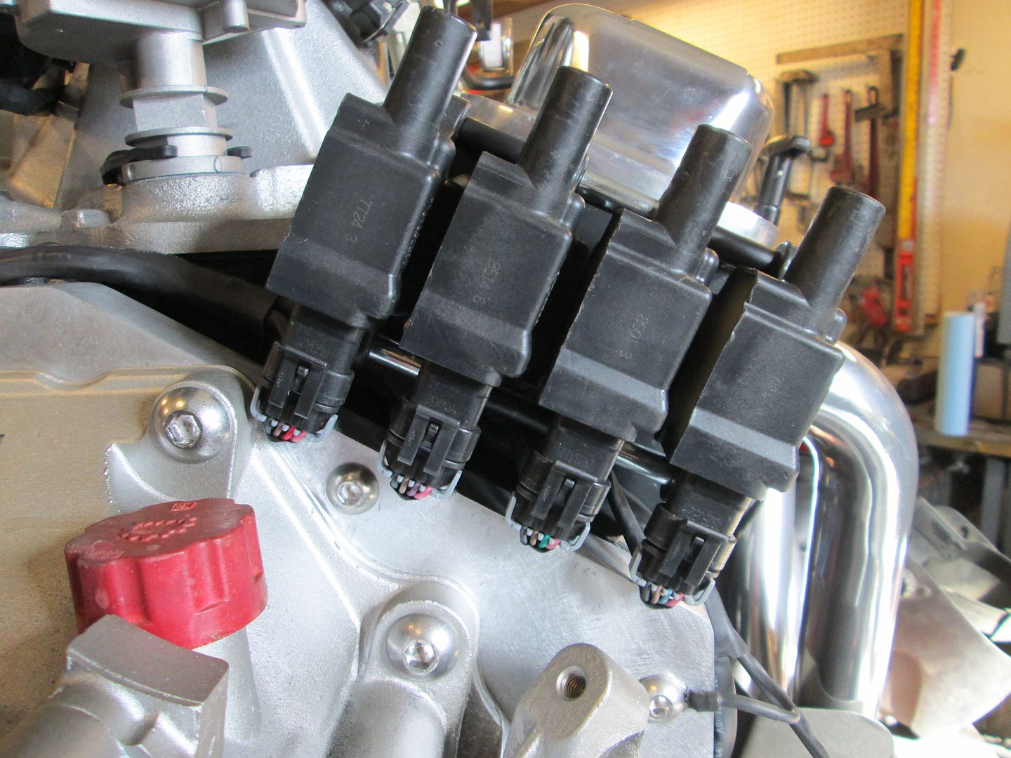
The coils need to be mounted, but I wanted to keep a little of the SBC/Distributor feel, so I fabbed up some coil brackets that bolt to the end of the heads. The plug wires will wrap the valve covers like a distributor setup, but terminate at the coils vs. the distributor:

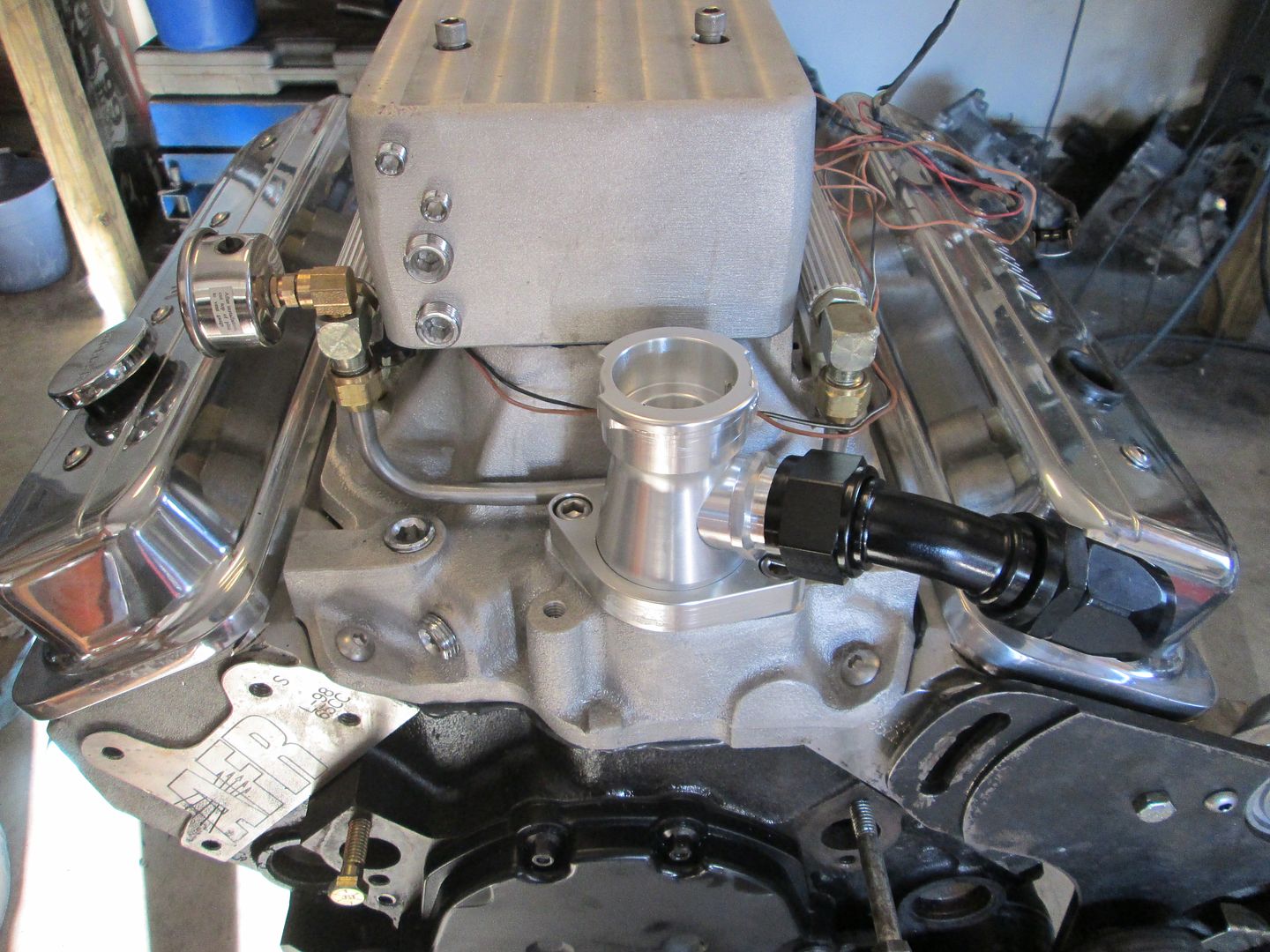
I wanted to run the fuel system return less, so I removed the fuel pressure regulator and machined a plug with o-ring to fit the hole and added a cap plate to hole it in place:
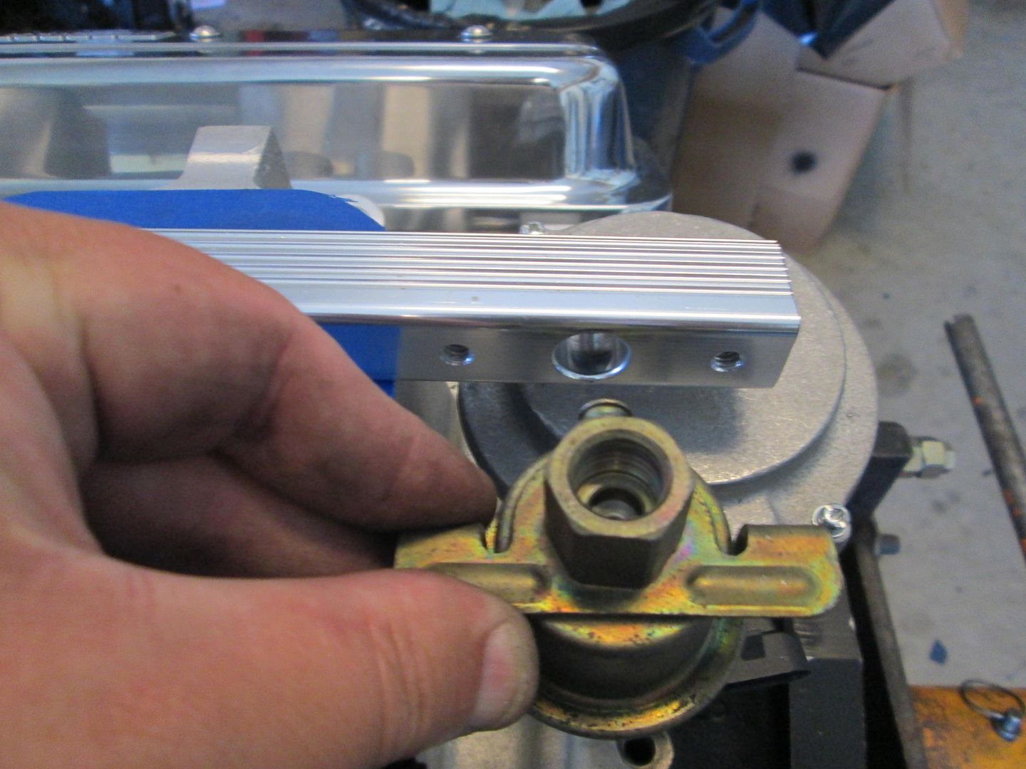
The fuel rail inlet:
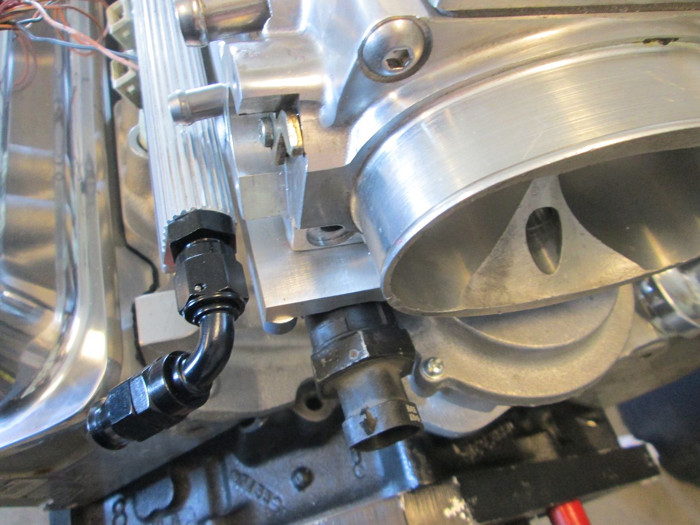
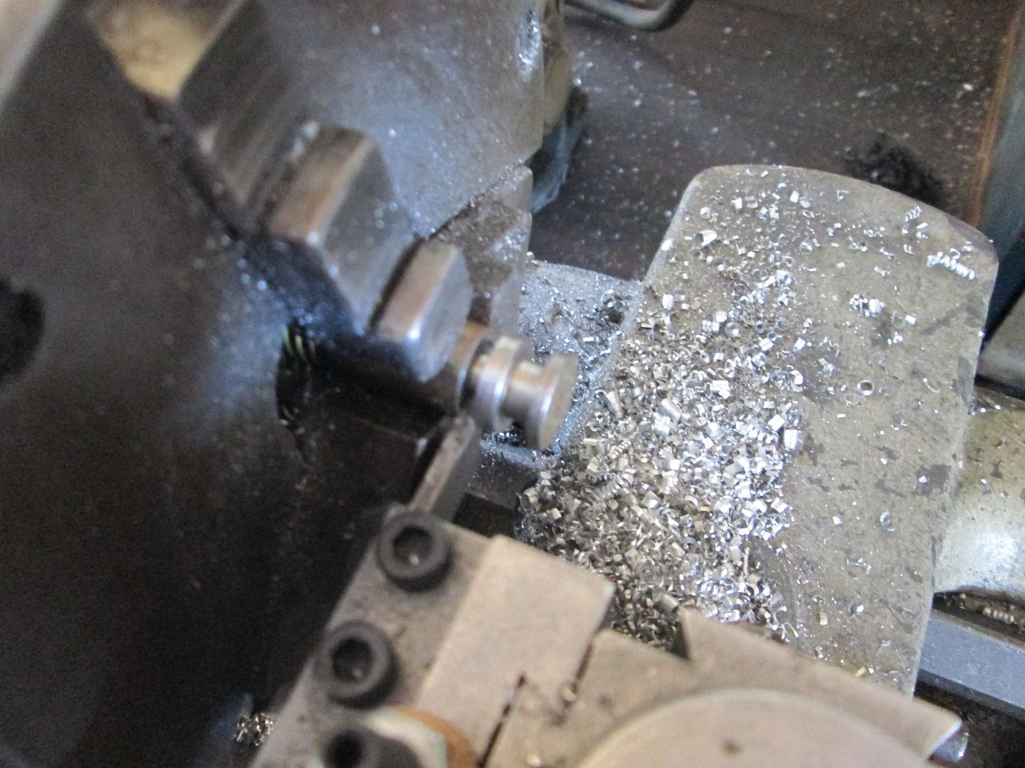
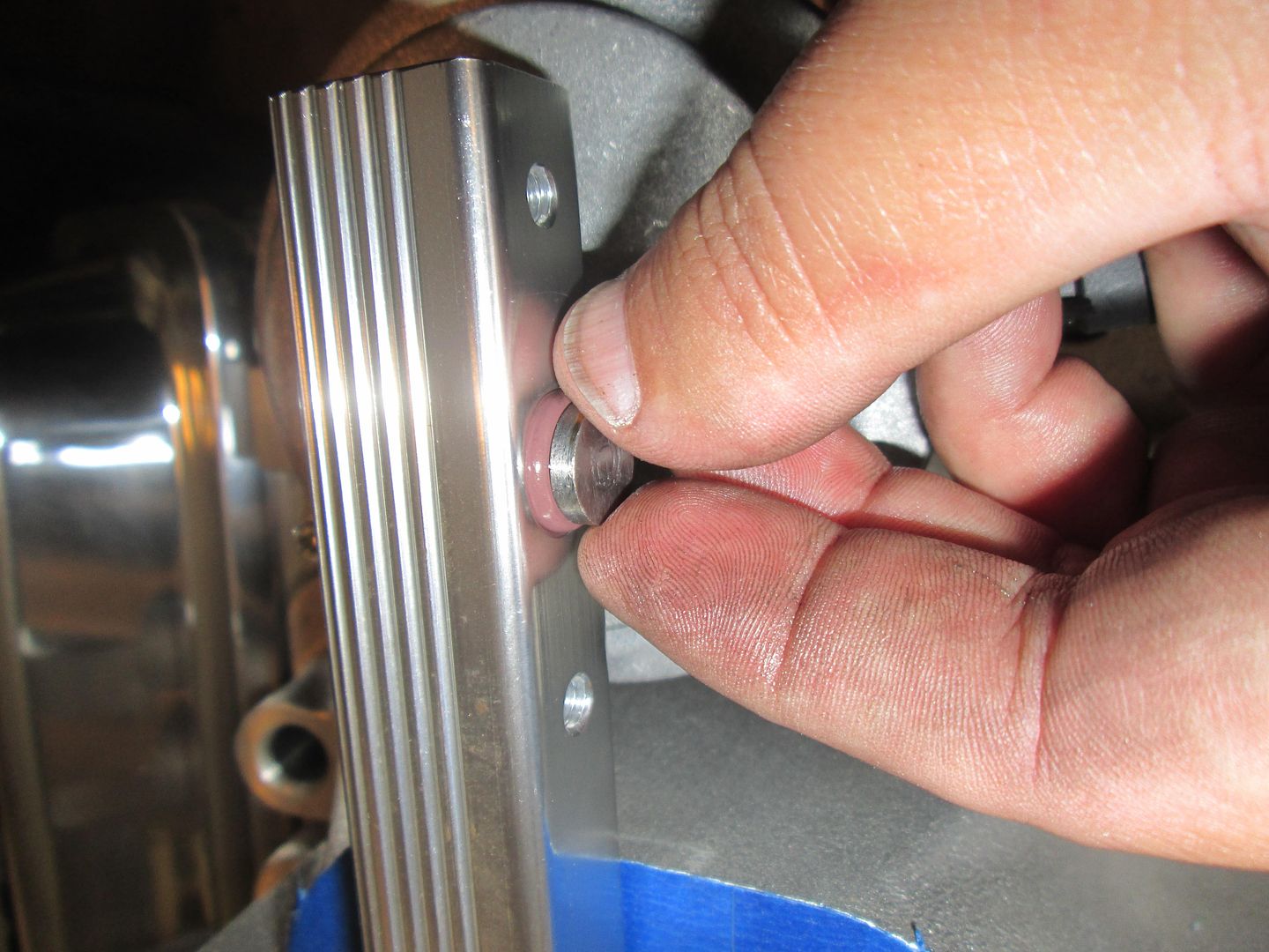
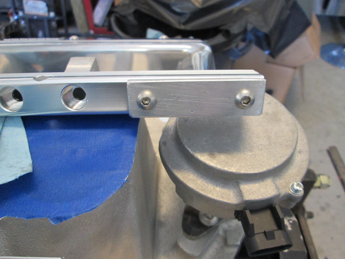
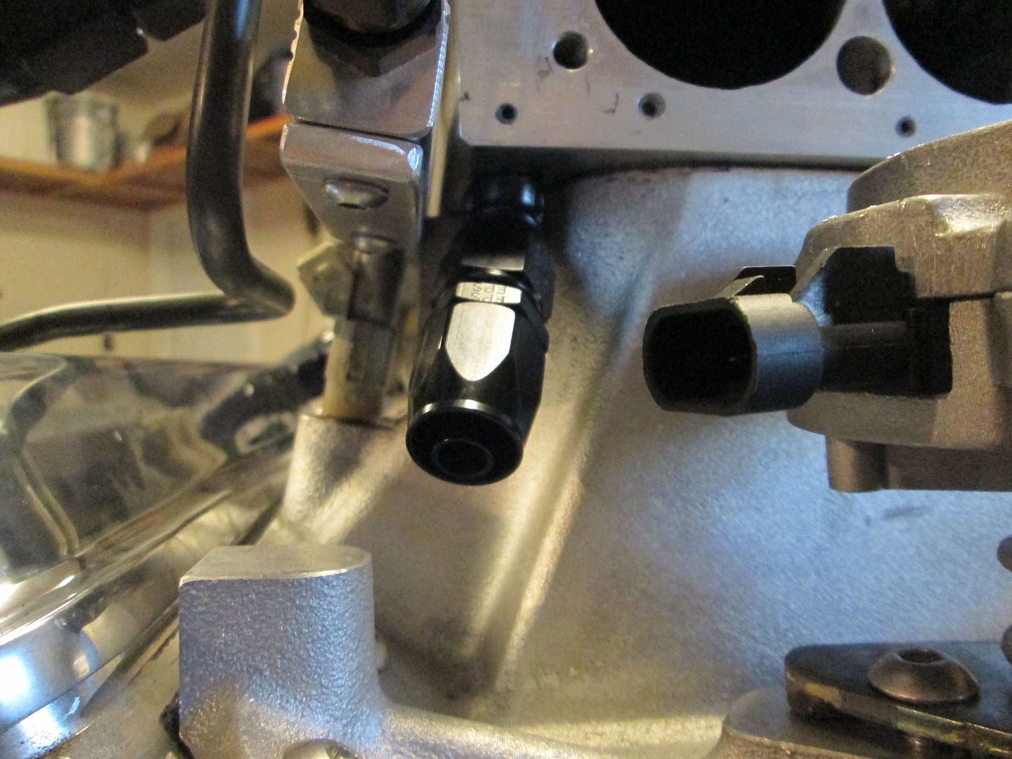
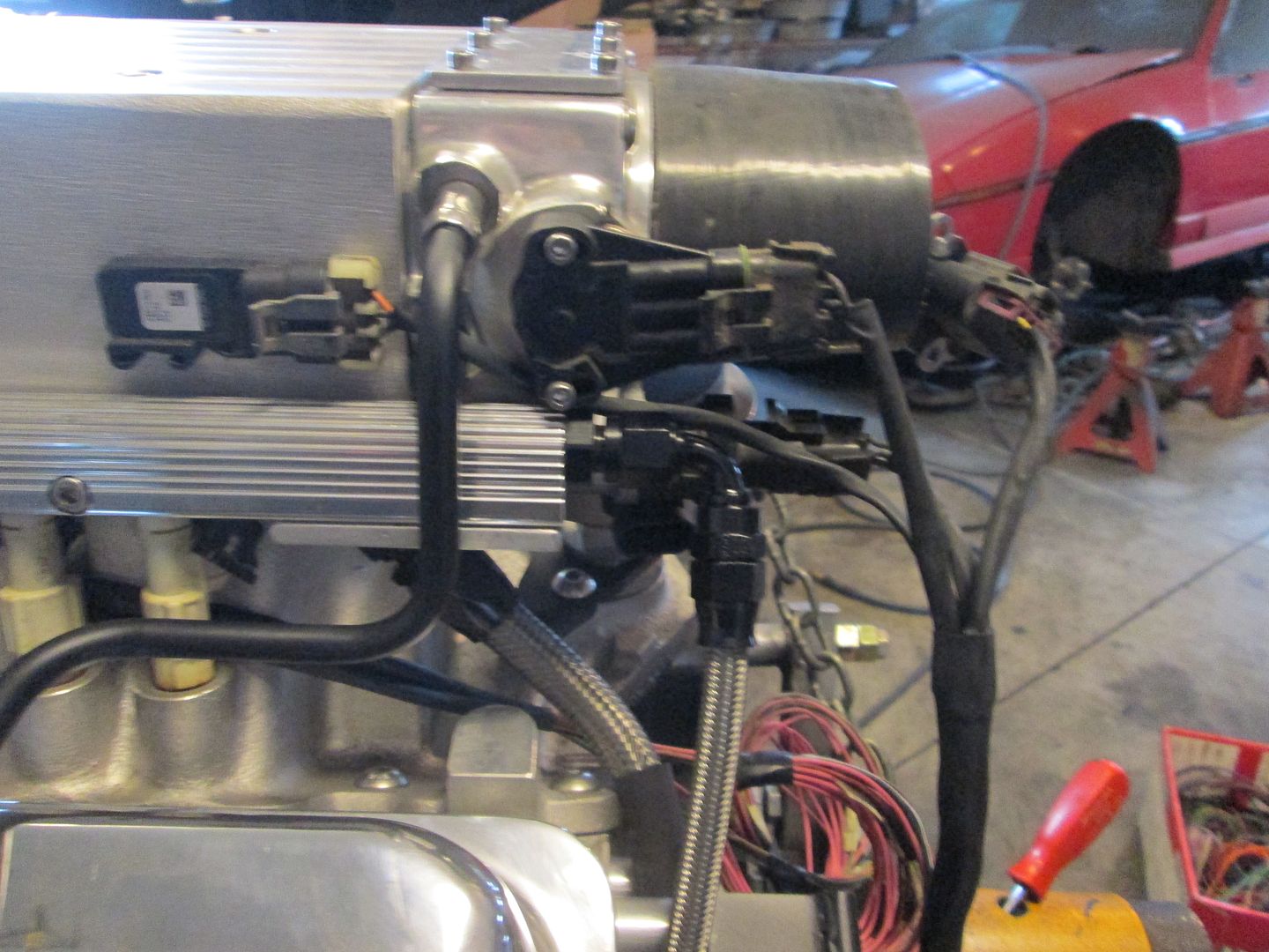
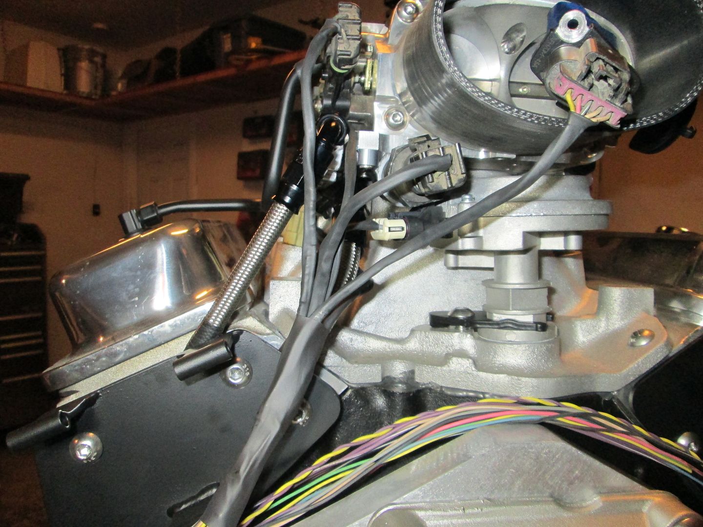
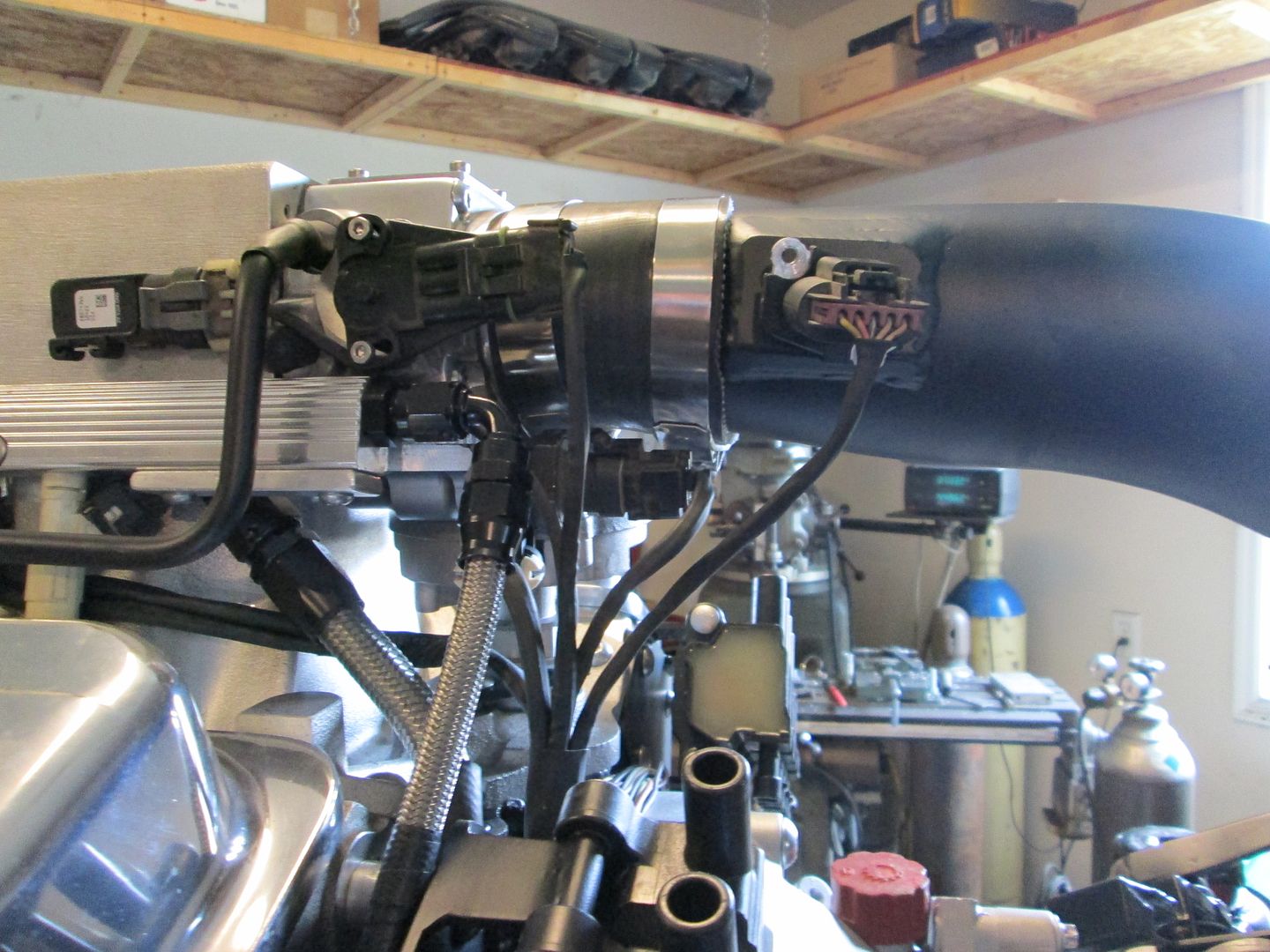
While playing with the fuel rails and upper plenum, I noticed that the injectors could be turned so the connectors would be mostly hidden. The only issue is there was no where for the wiring to go since the lower intake was machined down. So I stacked 3 cut off disks and cut a wiring path in the machine boss for the fuel rail:
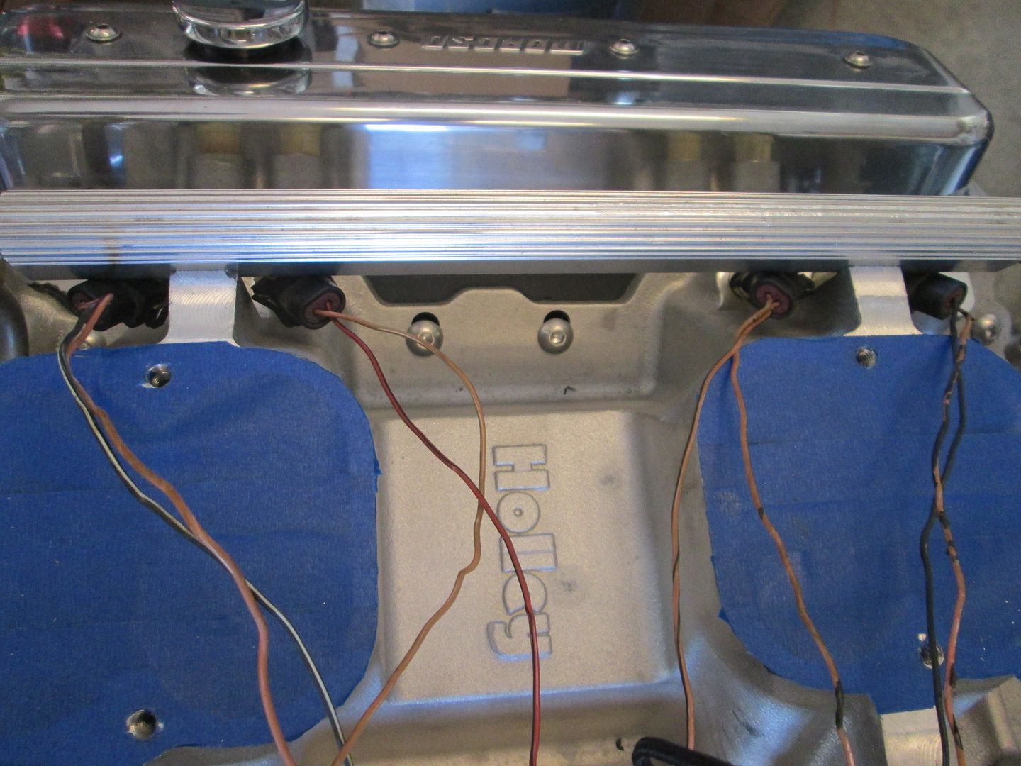
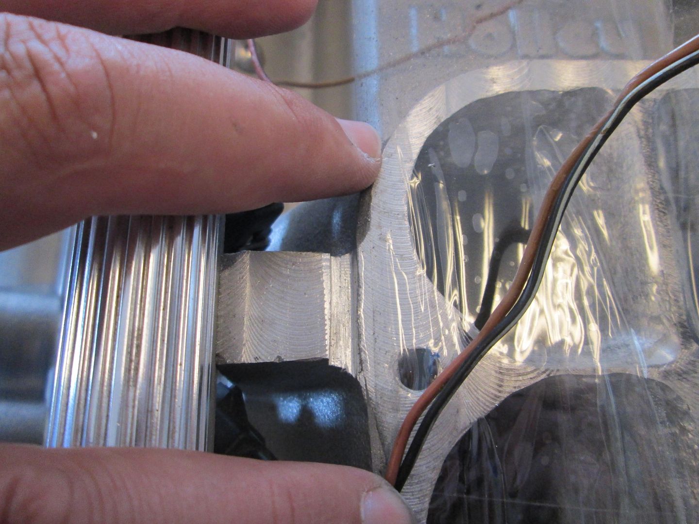
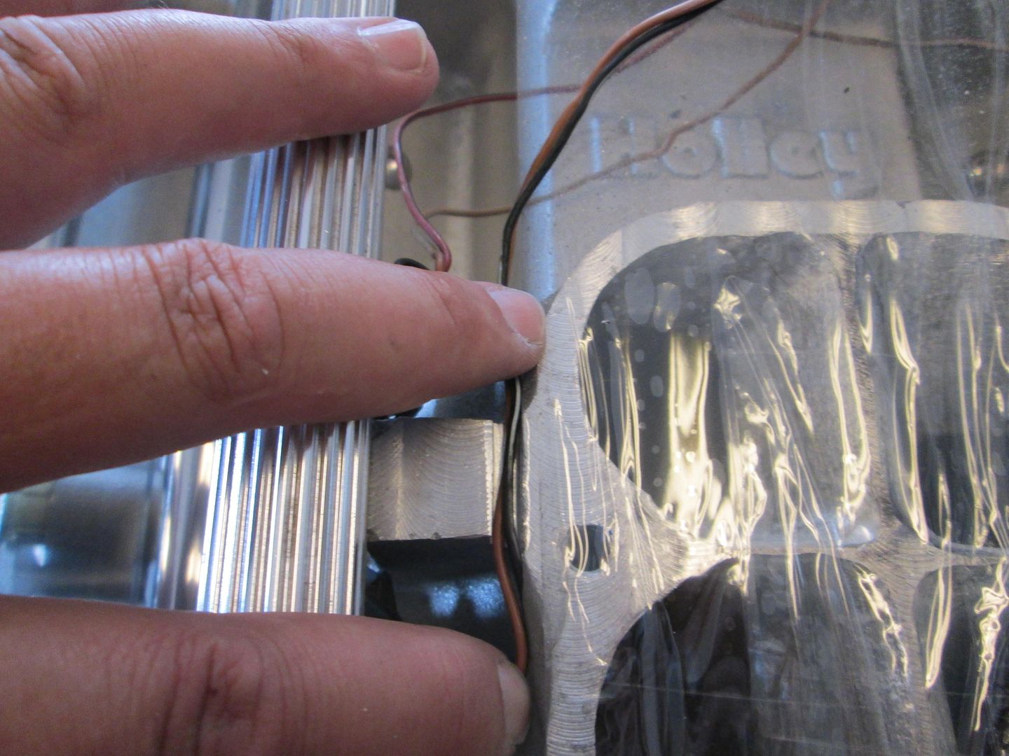
I like hidden wires!
I don't like hoses and other clutter, so I capped all the vacuum fittings on the plenum:
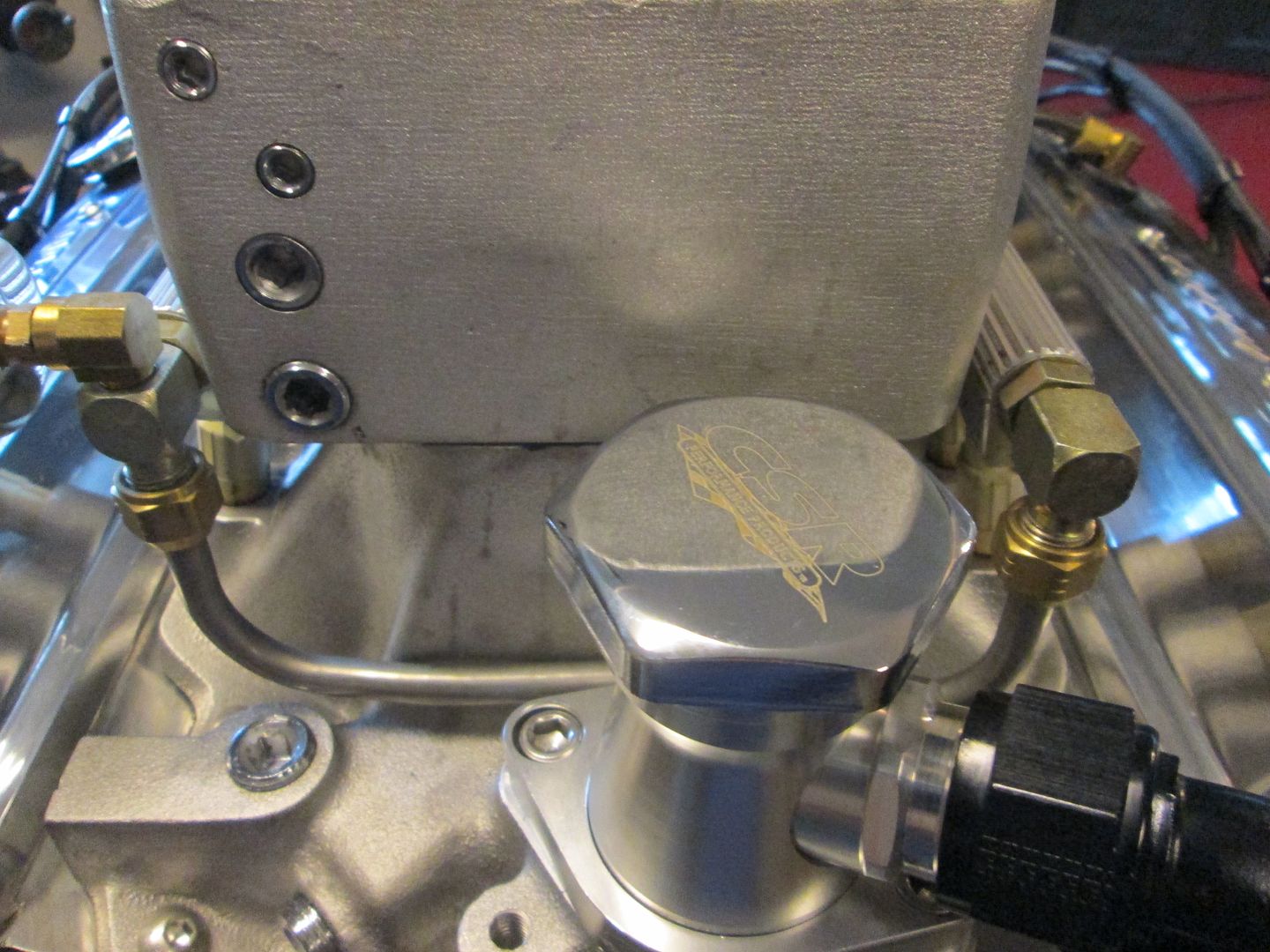
To run the vacuum line to the brake booster, I drilled/tapped a new hole on the bottom of the plenum. This corner of the intake is quite busy with everything be routed in this area:
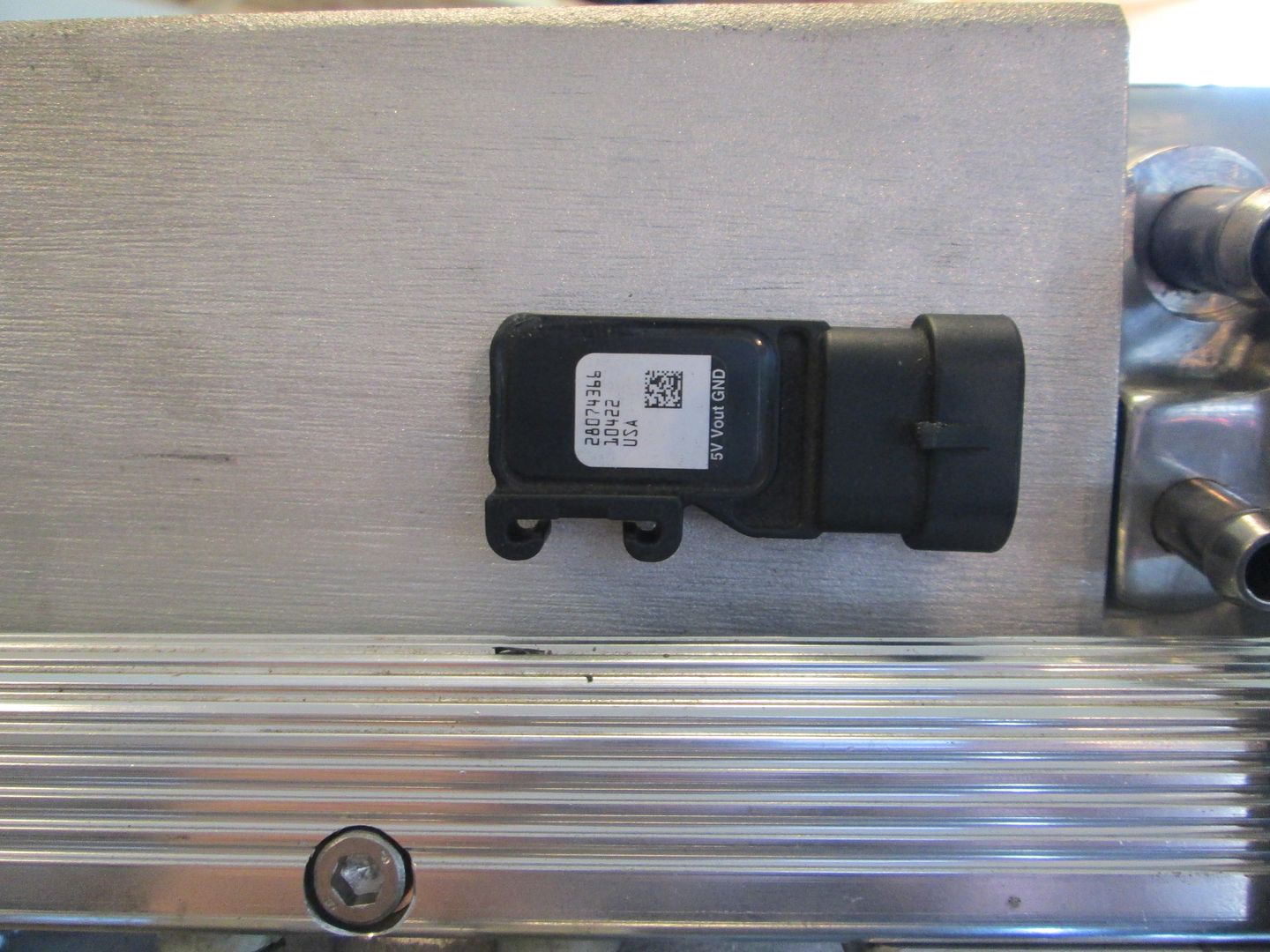
I drilled a new hole on the front side of the plenum for the MAP sensor:
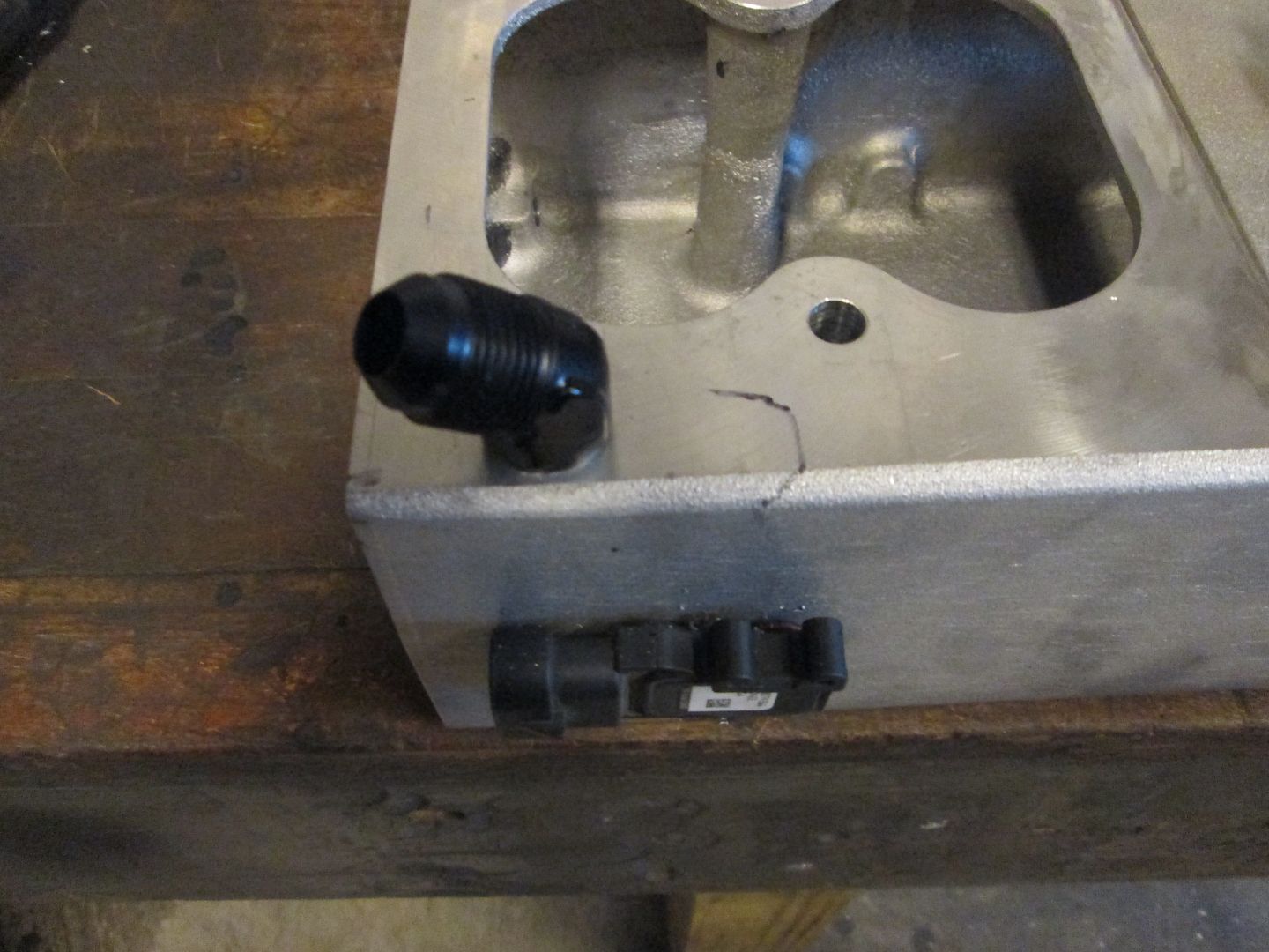
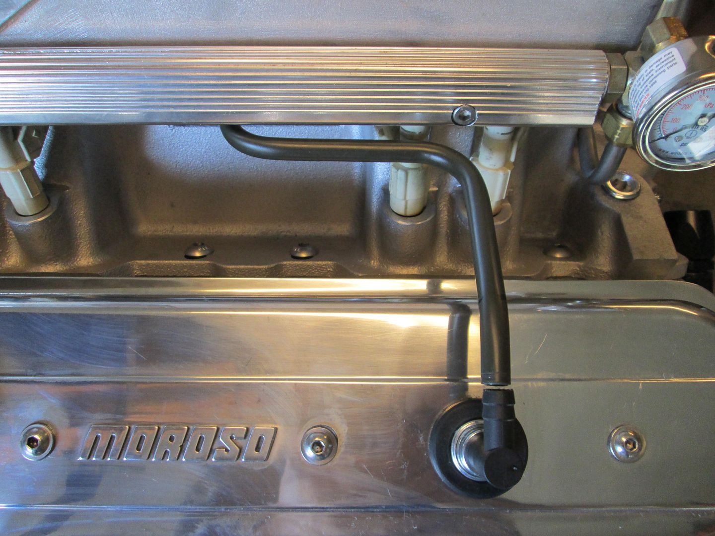
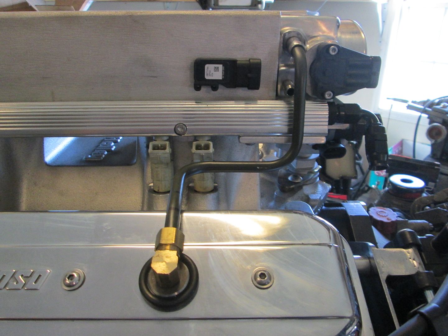
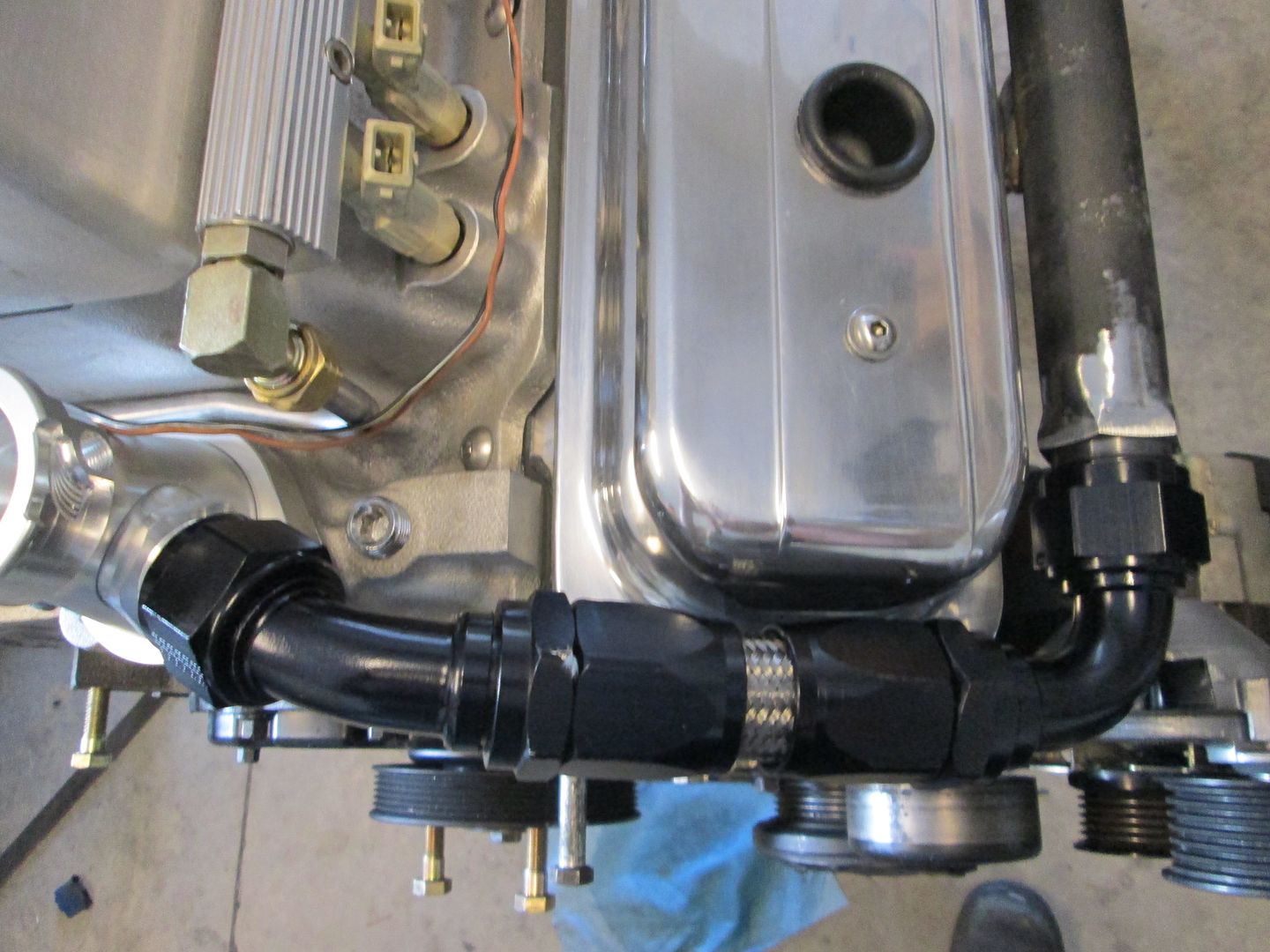
For the PCV routing, I used a threaded port on the underside of the plenum and bent up some 3/8" hardline for the routing. Then used 2 layers of heat shrink tube to for the connections:
For the clean air side, I made a fitting that would press into the valve covers and accept the compression fitting for the tube. Then bent up the hard line:
First step was removing the cover and sliding the reluctor wheel into place and checking its depth to the supplied spec:
The next step is to install the distributor and make sure it is lined up properly.
I had clocked the distributor housing so the cam sensor connector would point towards the front of the engine bay and be hidden, so I had to rework the supplied dist hold down bracket to work. I move the hole and added a support shelf to it:
I wanted to flip the plenum 180 so the throttle body would be over the transmission (Fiero style). The modifications to make the overall intake height shorter, didn't leave any room for the stock IAC housing to fit between the bottom of the TB and the distributor cover:
There was enough room for some 3/8" aluminum plate to fit, so I machined the bottom of the TB housing and machined passages into the plate to create new IAC passages. Then the IAC could bolt to the plate.
Then the intake, plenum and TB were mocked up to see if I could reverse the intake and still clear the distributor cover.
Stock bottom of the TB:
Post IAC passage machining - the sealing flange is black:
The aluminum plate with the same IAC passages machined into it as well as the holes to acces the stock IAC housing:
IAC housing mounted to the new offset plate:
The coils need to be mounted, but I wanted to keep a little of the SBC/Distributor feel, so I fabbed up some coil brackets that bolt to the end of the heads. The plug wires will wrap the valve covers like a distributor setup, but terminate at the coils vs. the distributor:
I wanted to run the fuel system return less, so I removed the fuel pressure regulator and machined a plug with o-ring to fit the hole and added a cap plate to hole it in place:
The fuel rail inlet:
While playing with the fuel rails and upper plenum, I noticed that the injectors could be turned so the connectors would be mostly hidden. The only issue is there was no where for the wiring to go since the lower intake was machined down. So I stacked 3 cut off disks and cut a wiring path in the machine boss for the fuel rail:
I like hidden wires!
I don't like hoses and other clutter, so I capped all the vacuum fittings on the plenum:
To run the vacuum line to the brake booster, I drilled/tapped a new hole on the bottom of the plenum. This corner of the intake is quite busy with everything be routed in this area:
I drilled a new hole on the front side of the plenum for the MAP sensor:
For the PCV routing, I used a threaded port on the underside of the plenum and bent up some 3/8" hardline for the routing. Then used 2 layers of heat shrink tube to for the connections:
For the clean air side, I made a fitting that would press into the valve covers and accept the compression fitting for the tube. Then bent up the hard line:
Last edited by fieroguru; 06-15-2014 at 05:26 PM.
06-15-2014, 02:06 PM
#6
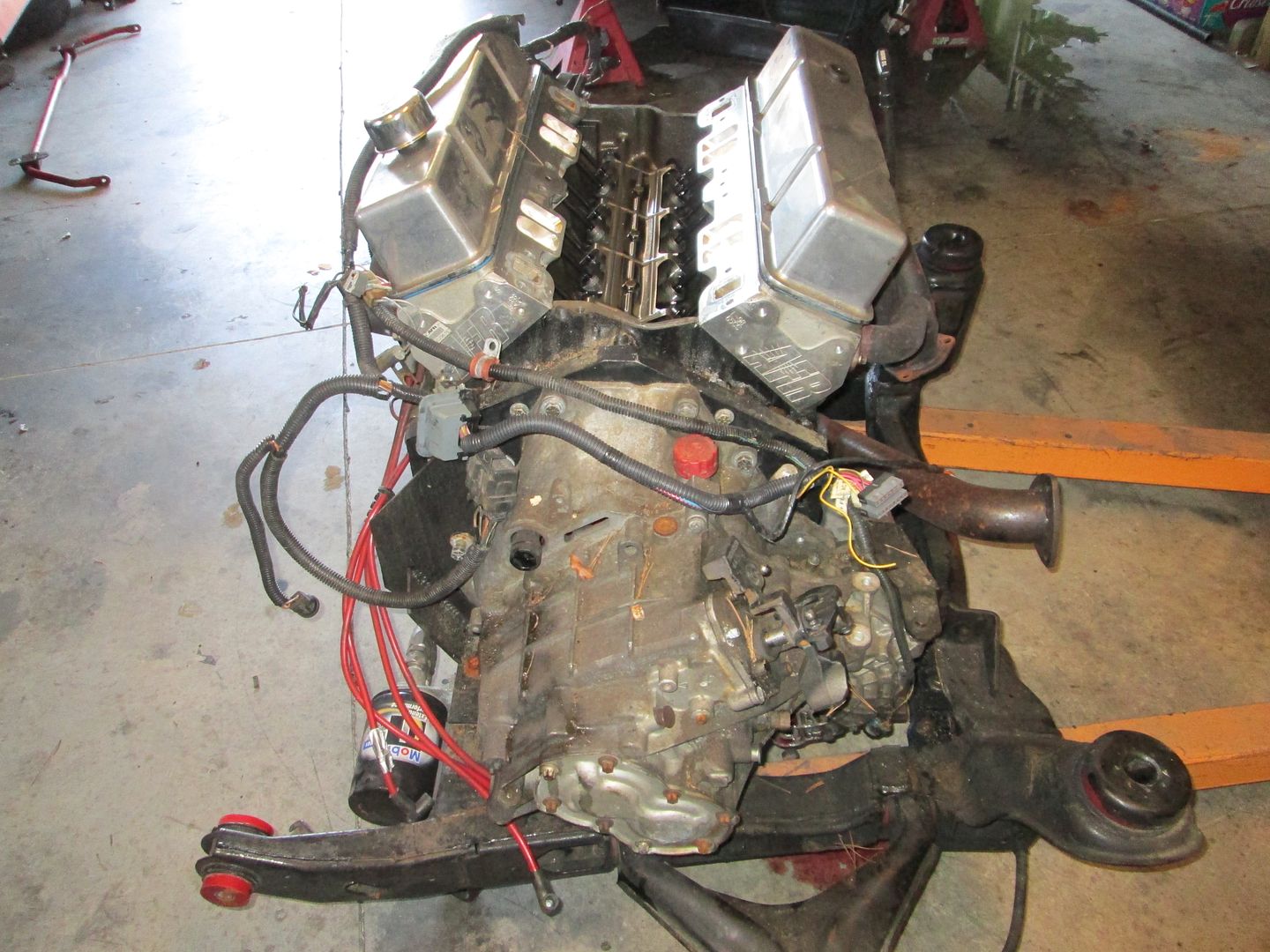
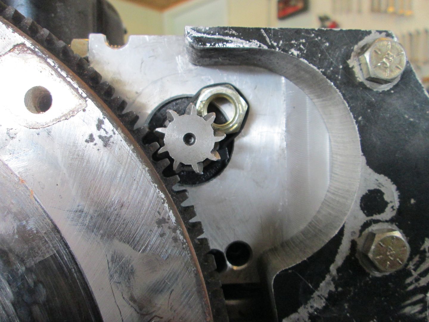
On a SBC Fiero, the transmission half shaft is right where the SBC starter goes. So it must be relocated to the other side (where the oil filter is), so the oil filter must be relocated.
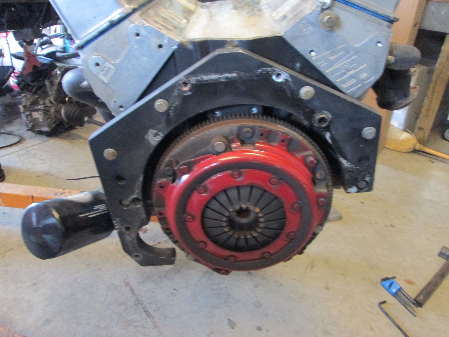
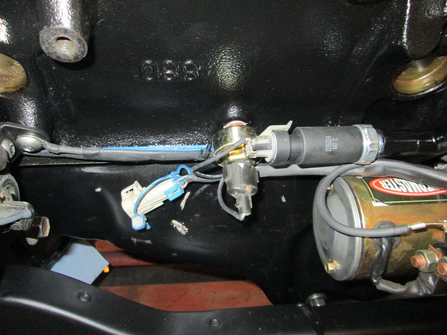
The Archie SBC kit uses a 158 tooth flywheel, but its ring gear does not clear the F23... so this car had previously had the flywheel modified to use a 142 tooth ring gear. No issues with the flywheel mod, but the smaller flywheel means the starter had to go in further. Here is the mounting block when it arrived - slotted holes and lots of spacers. The owner was having issues getting it to properly mesh:
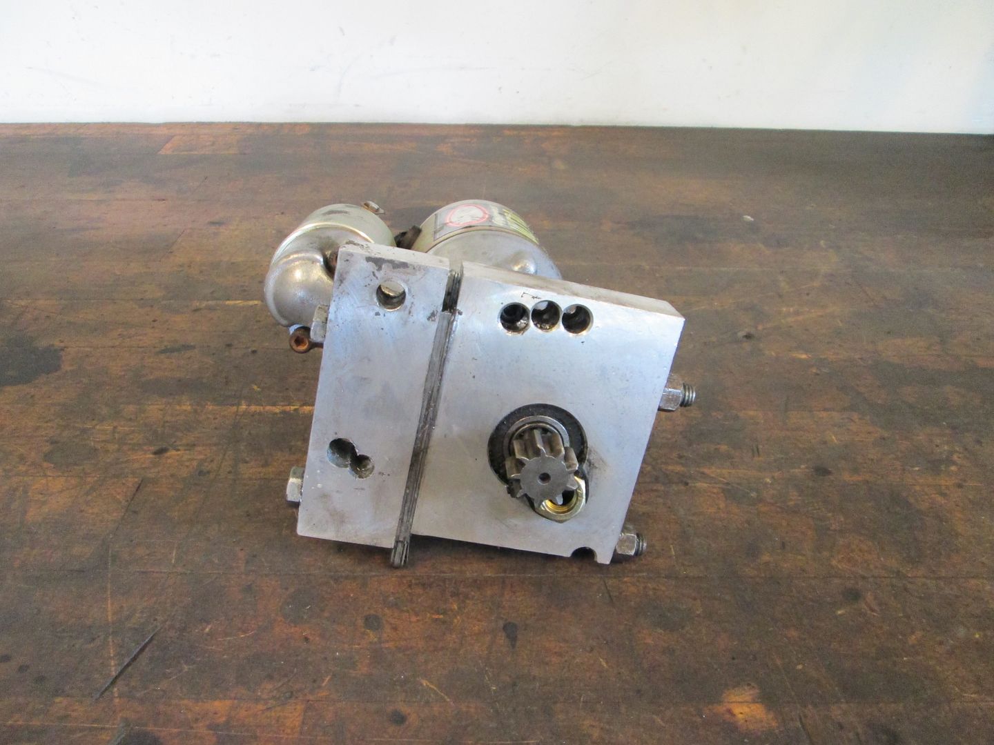
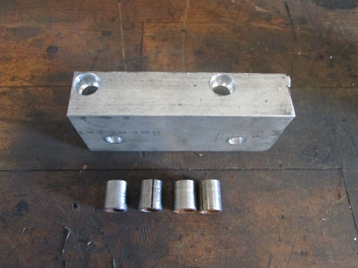
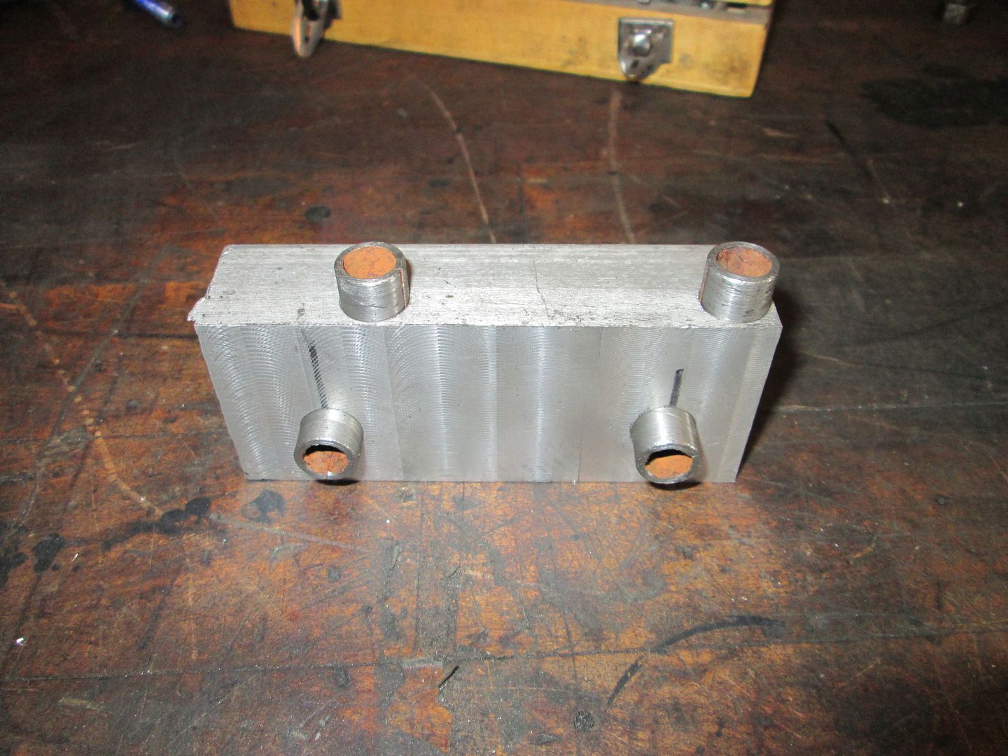
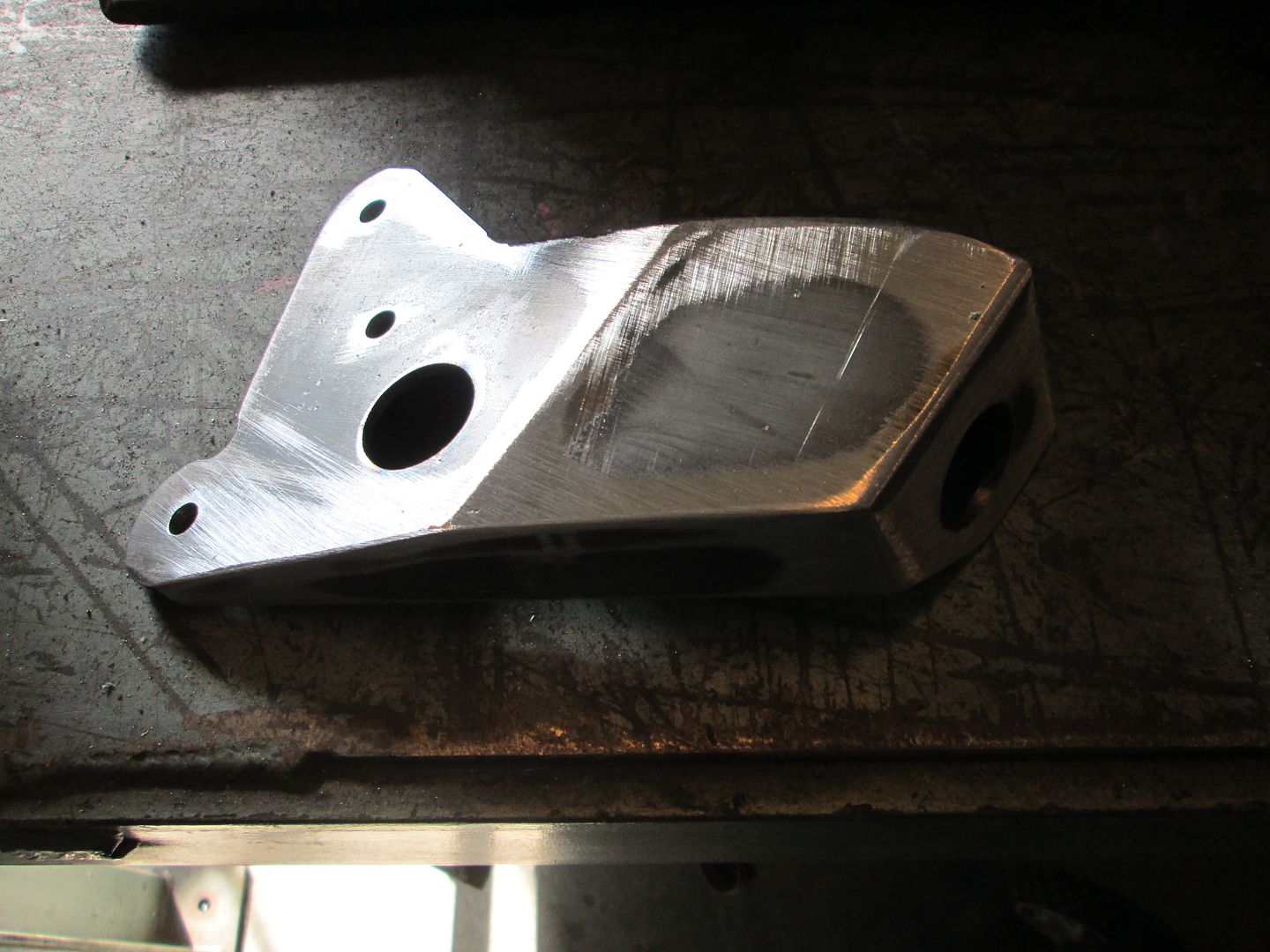
So I machined a new starter block and added dowel pins for all bolt interfaces so it could be precisely positioned with ease.
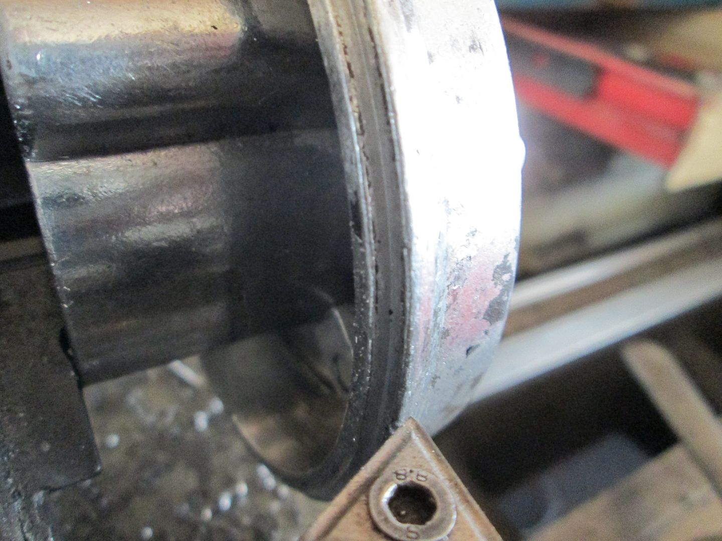
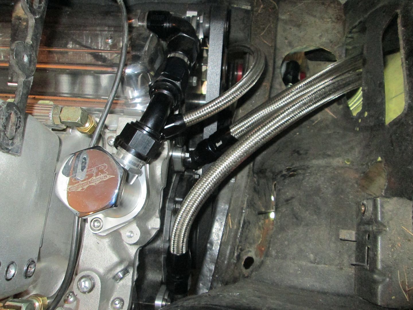
The oil filter bypass is the source for many SBC fiero oil leaks. Its just hard to get a good seal with the supplied gaskets. Several years back I found an oil filter with the right OD seal and figured out I could machine the bypass housing to accept it.
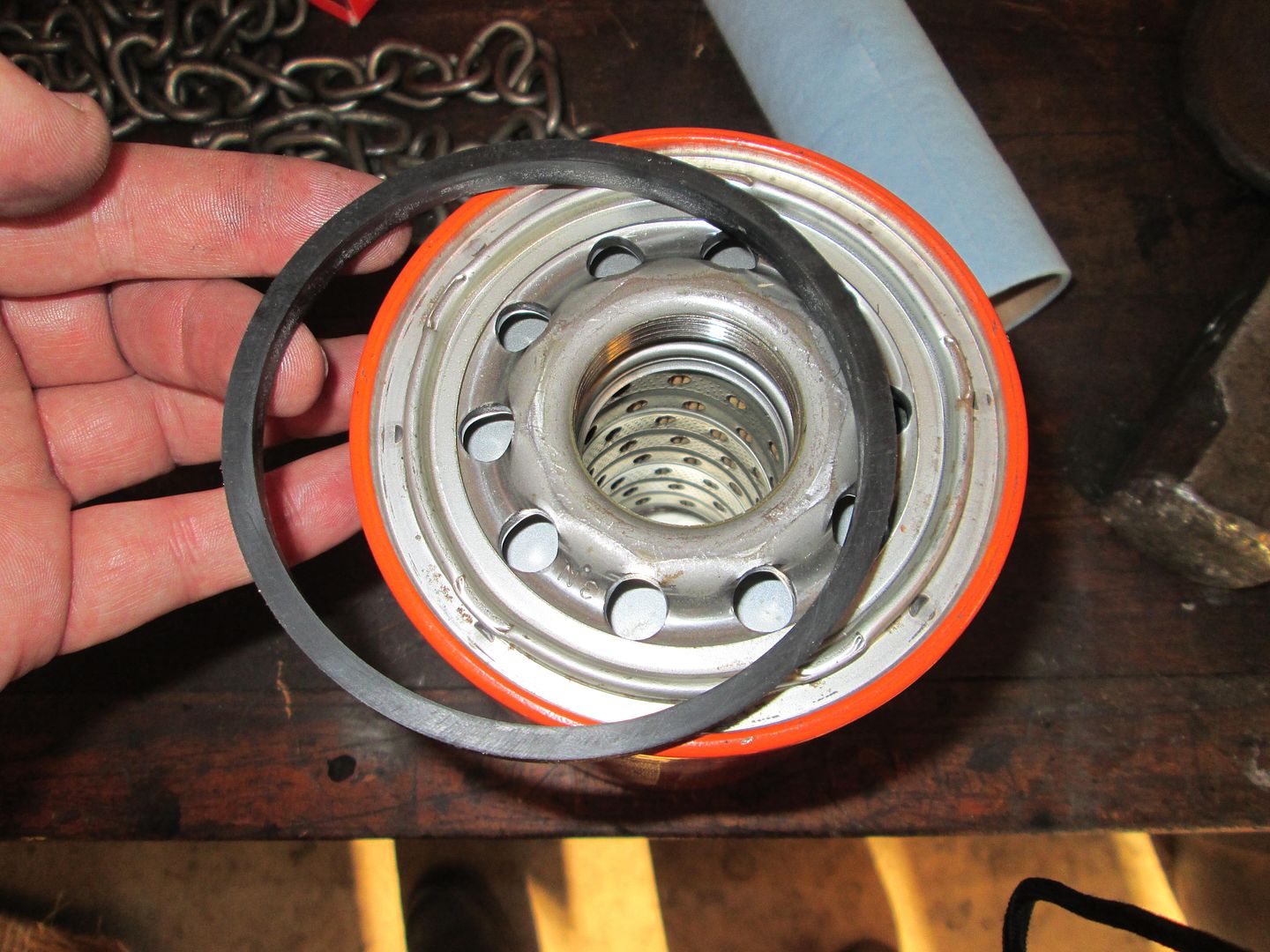
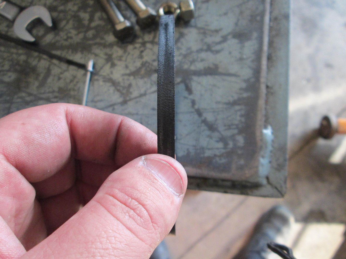
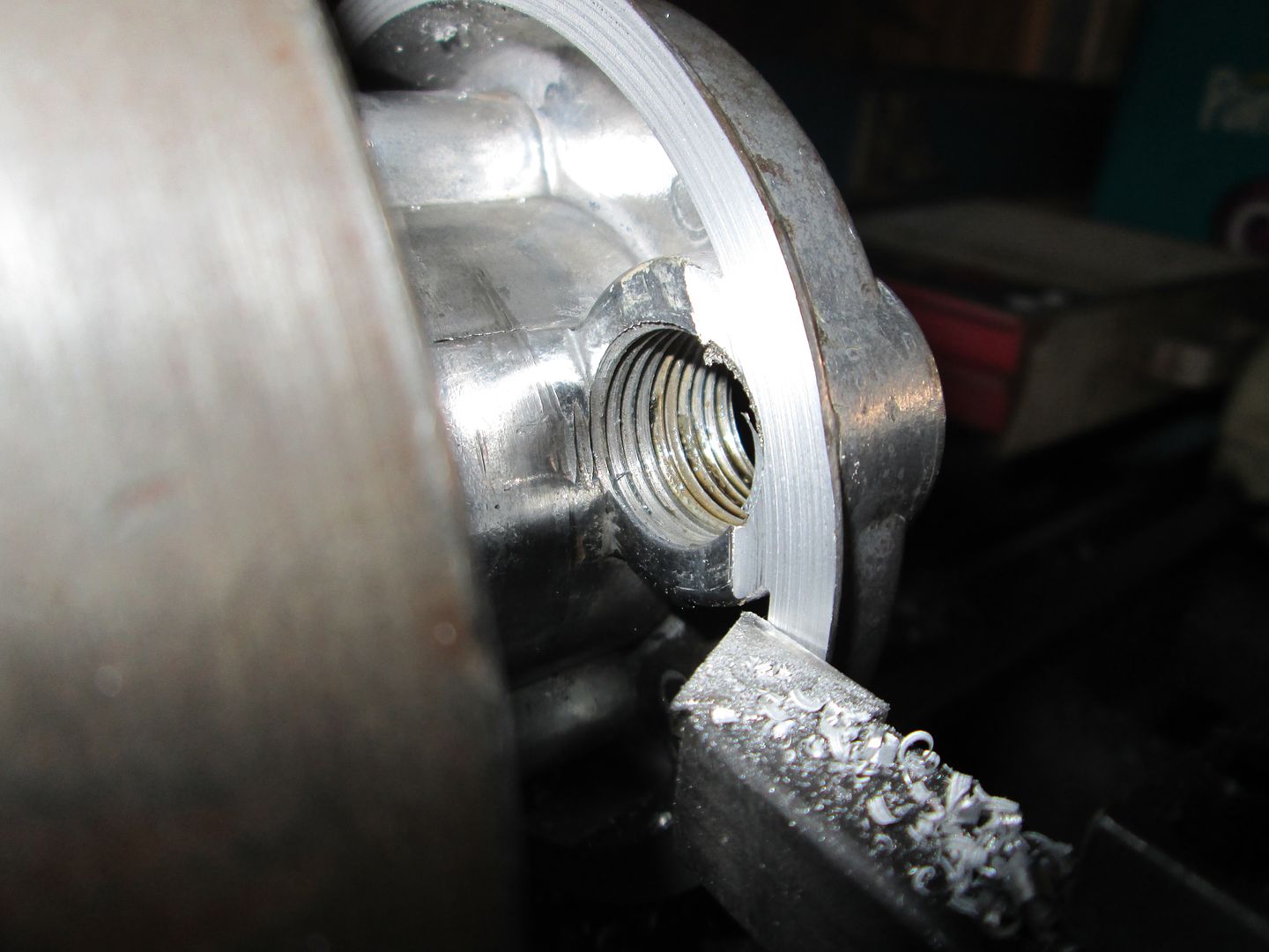
To use the O-ring, the stock flange on the bypass plate must be turned flat and material removed to make room for the thicker o-ring seal:
Stock flange:
After machining:
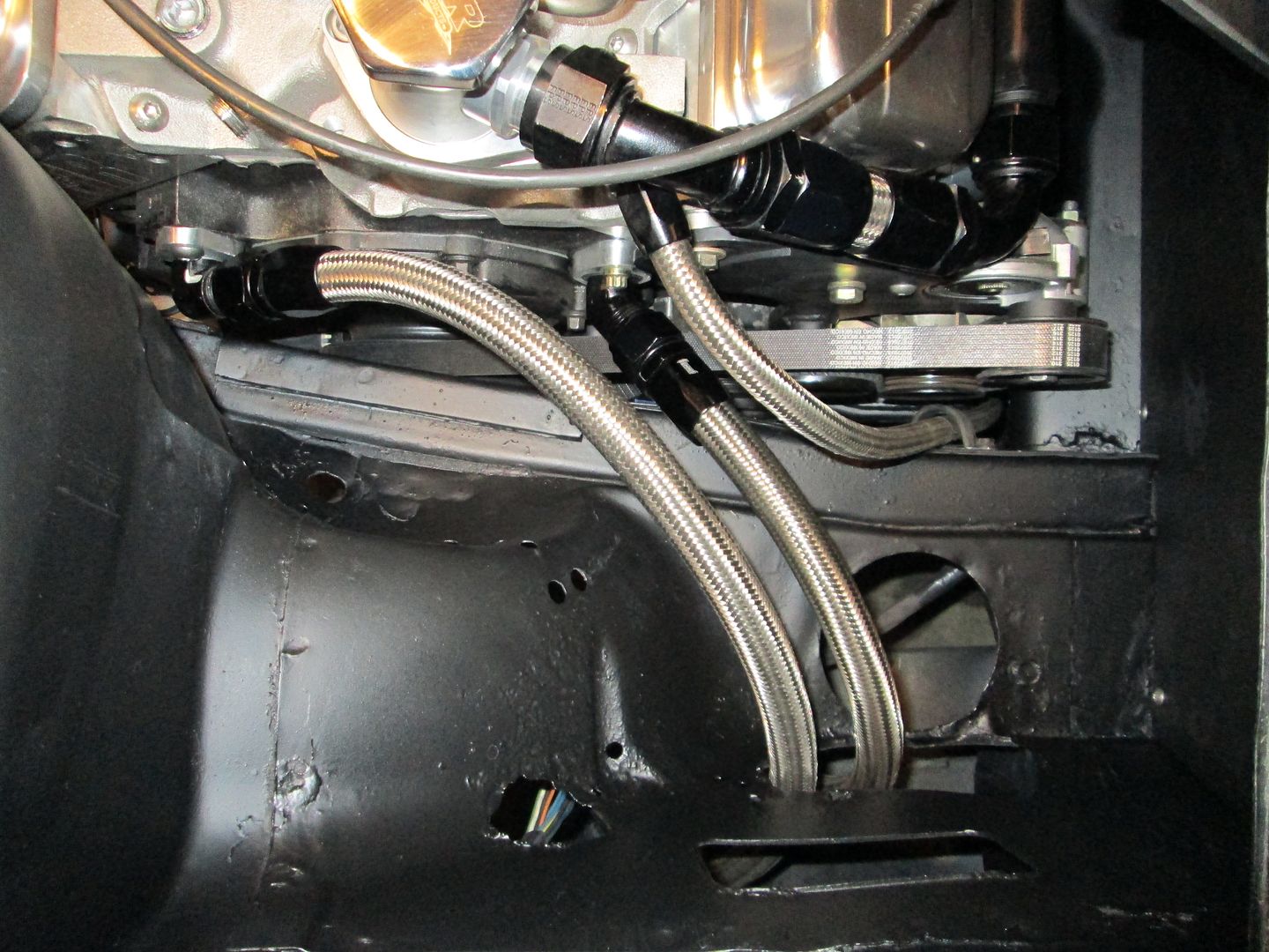
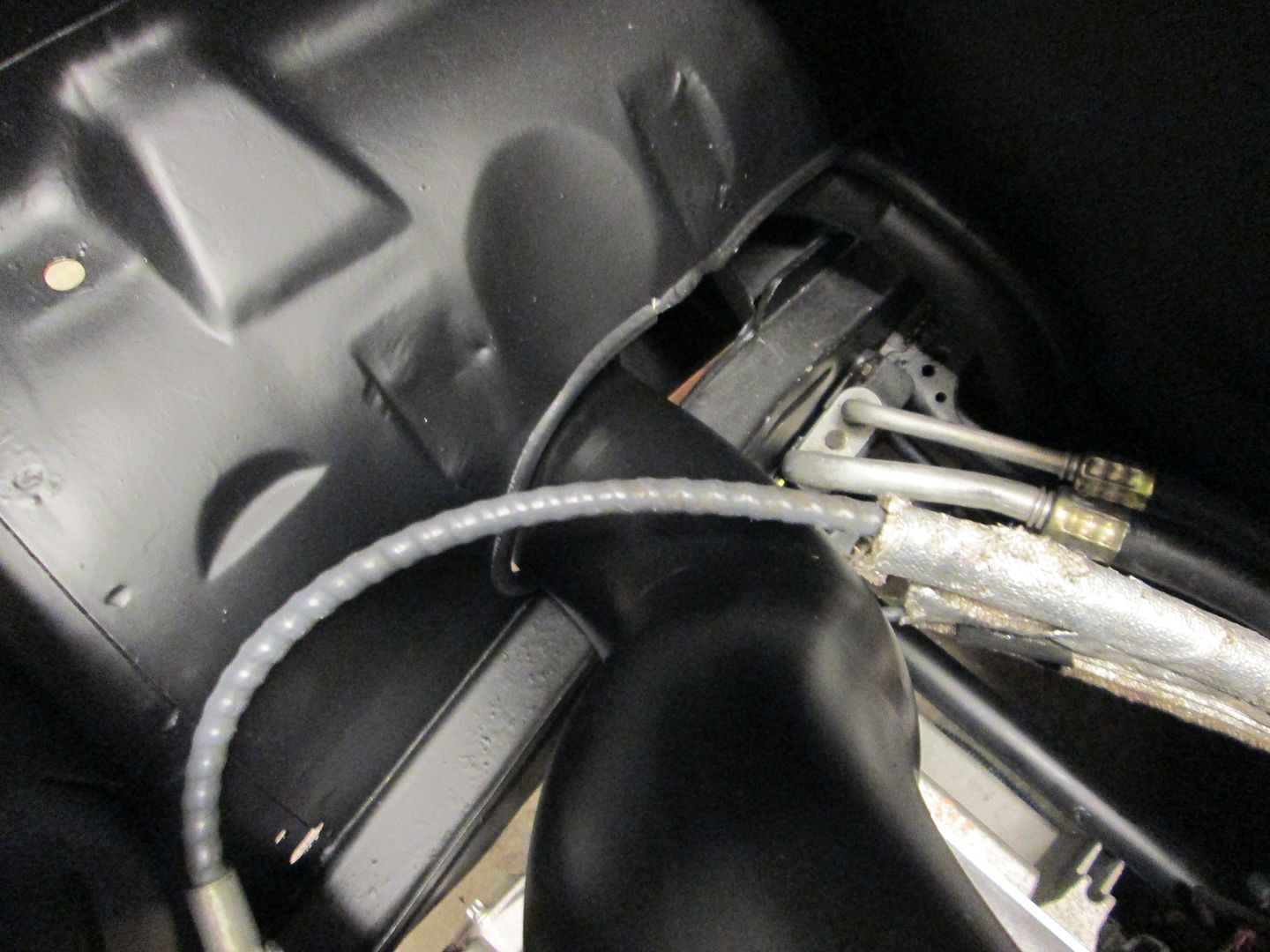
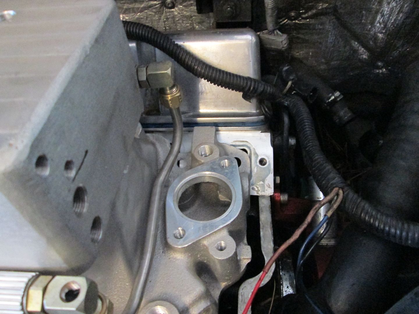
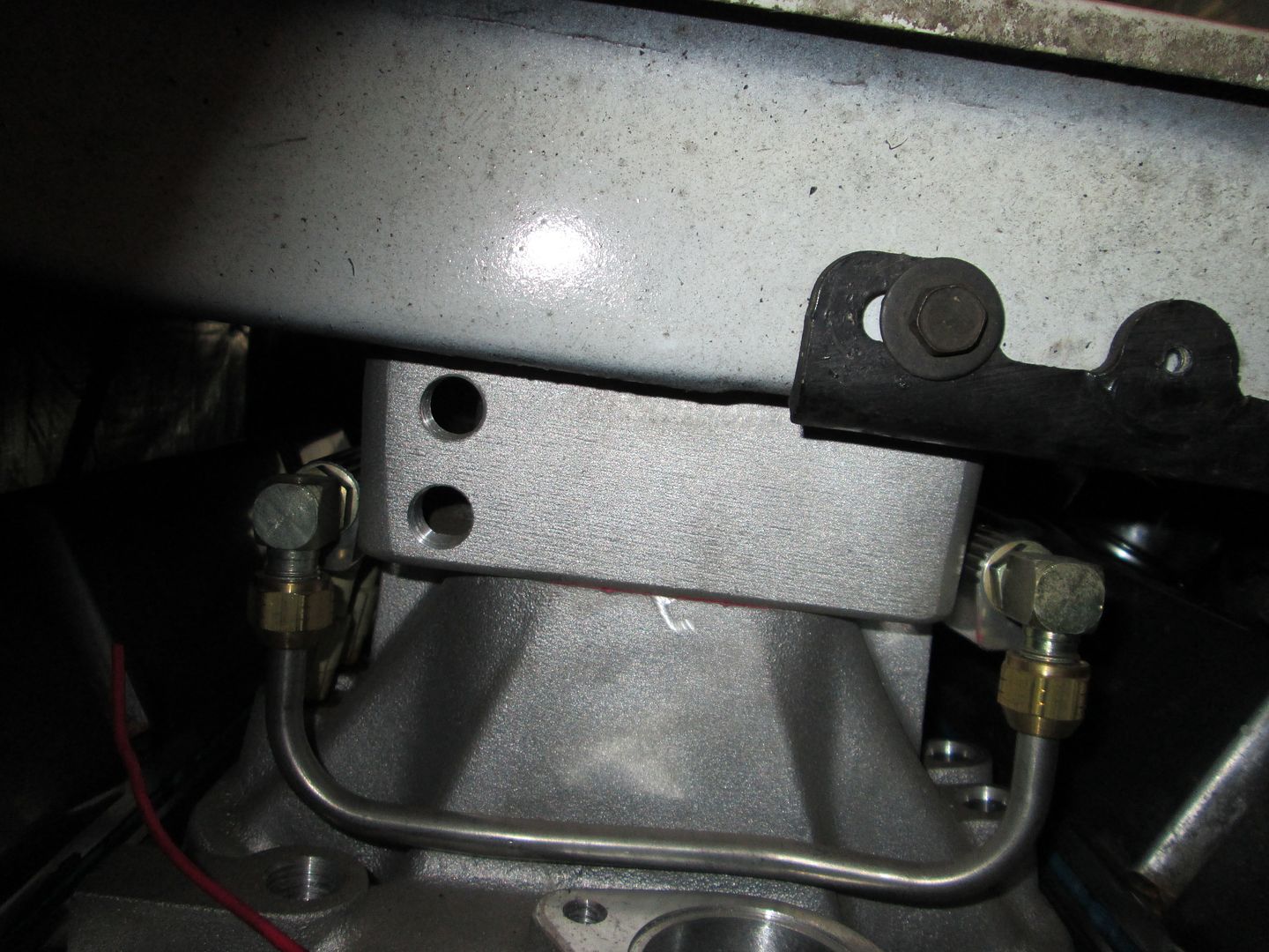
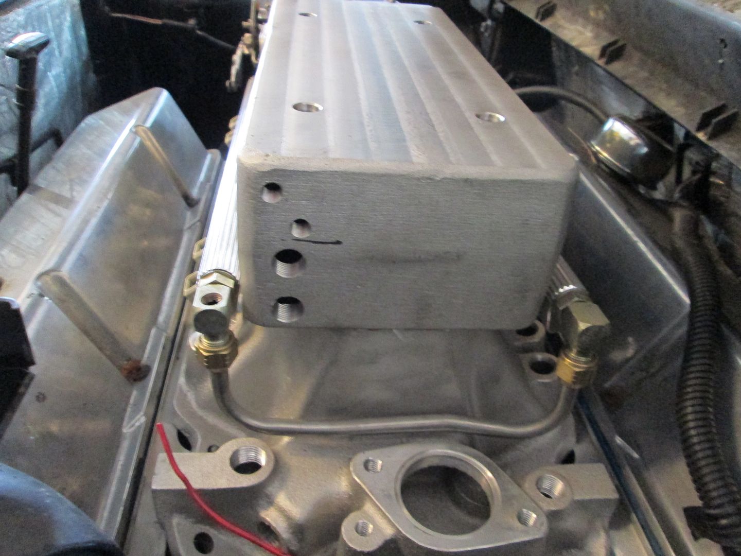
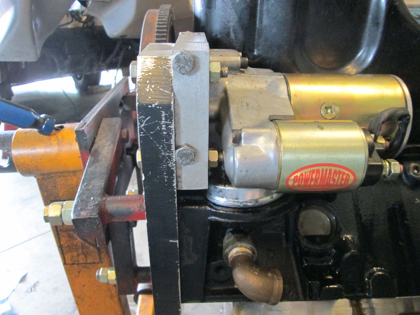
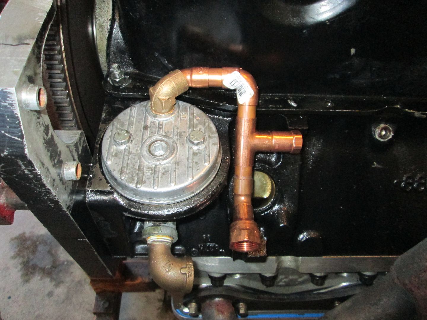
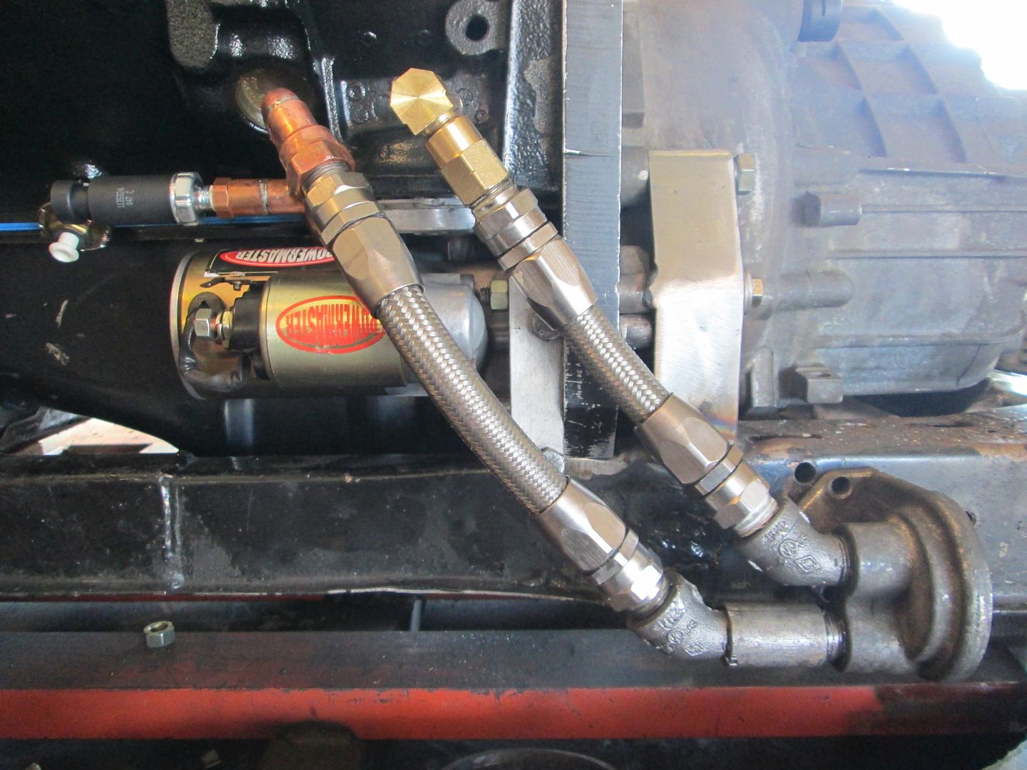
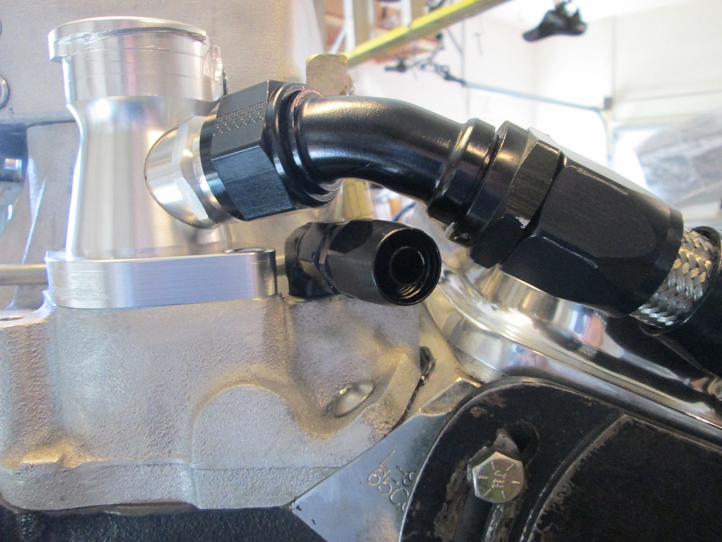
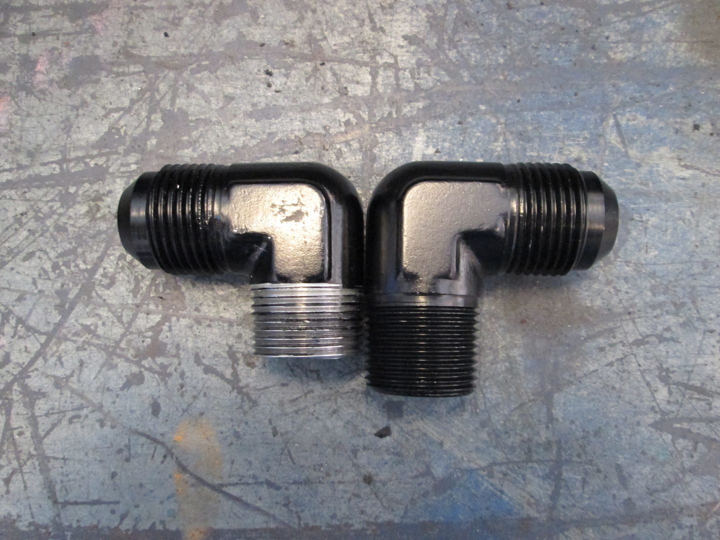
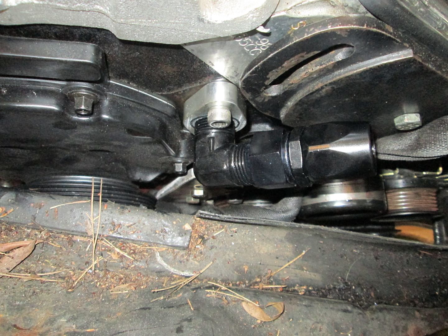
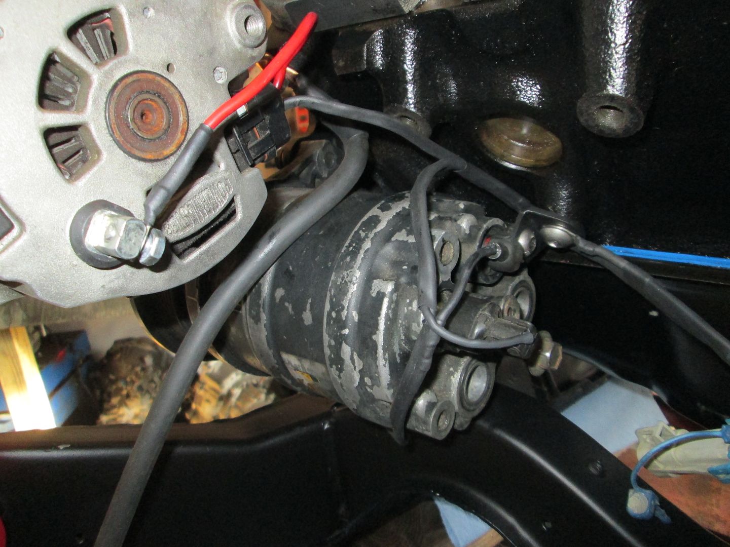
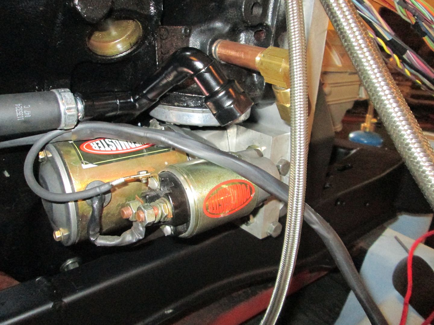
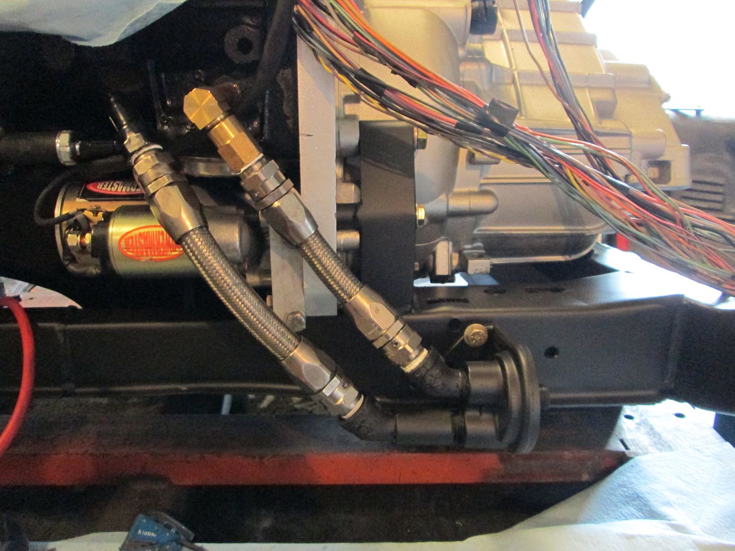
With the starter being pushed in further for the smaller flywheel, room for the oil bypass fitting became very minimal. By using some brass fittings and copper lines I was able to clear the starter:
Here are the braided stainless lines that connect to the remove oil filter housing:
The Archie SBC kit uses a 158 tooth flywheel, but its ring gear does not clear the F23... so this car had previously had the flywheel modified to use a 142 tooth ring gear. No issues with the flywheel mod, but the smaller flywheel means the starter had to go in further. Here is the mounting block when it arrived - slotted holes and lots of spacers. The owner was having issues getting it to properly mesh:
So I machined a new starter block and added dowel pins for all bolt interfaces so it could be precisely positioned with ease.
The oil filter bypass is the source for many SBC fiero oil leaks. Its just hard to get a good seal with the supplied gaskets. Several years back I found an oil filter with the right OD seal and figured out I could machine the bypass housing to accept it.
To use the O-ring, the stock flange on the bypass plate must be turned flat and material removed to make room for the thicker o-ring seal:
Stock flange:
After machining:
With the starter being pushed in further for the smaller flywheel, room for the oil bypass fitting became very minimal. By using some brass fittings and copper lines I was able to clear the starter:
Here are the braided stainless lines that connect to the remove oil filter housing:
Last edited by fieroguru; 06-15-2014 at 05:01 PM.
06-15-2014, 02:13 PM
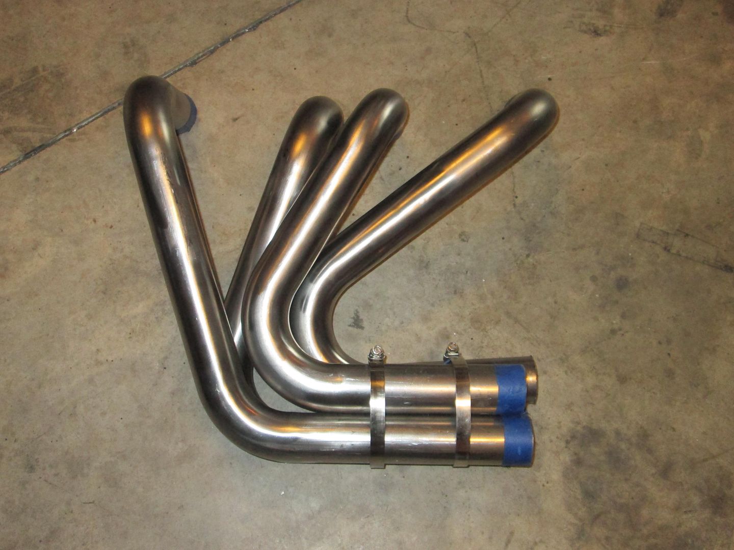
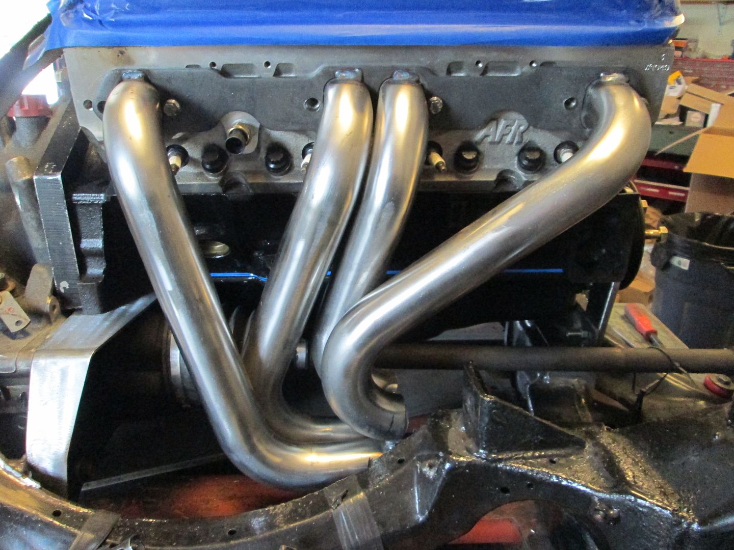
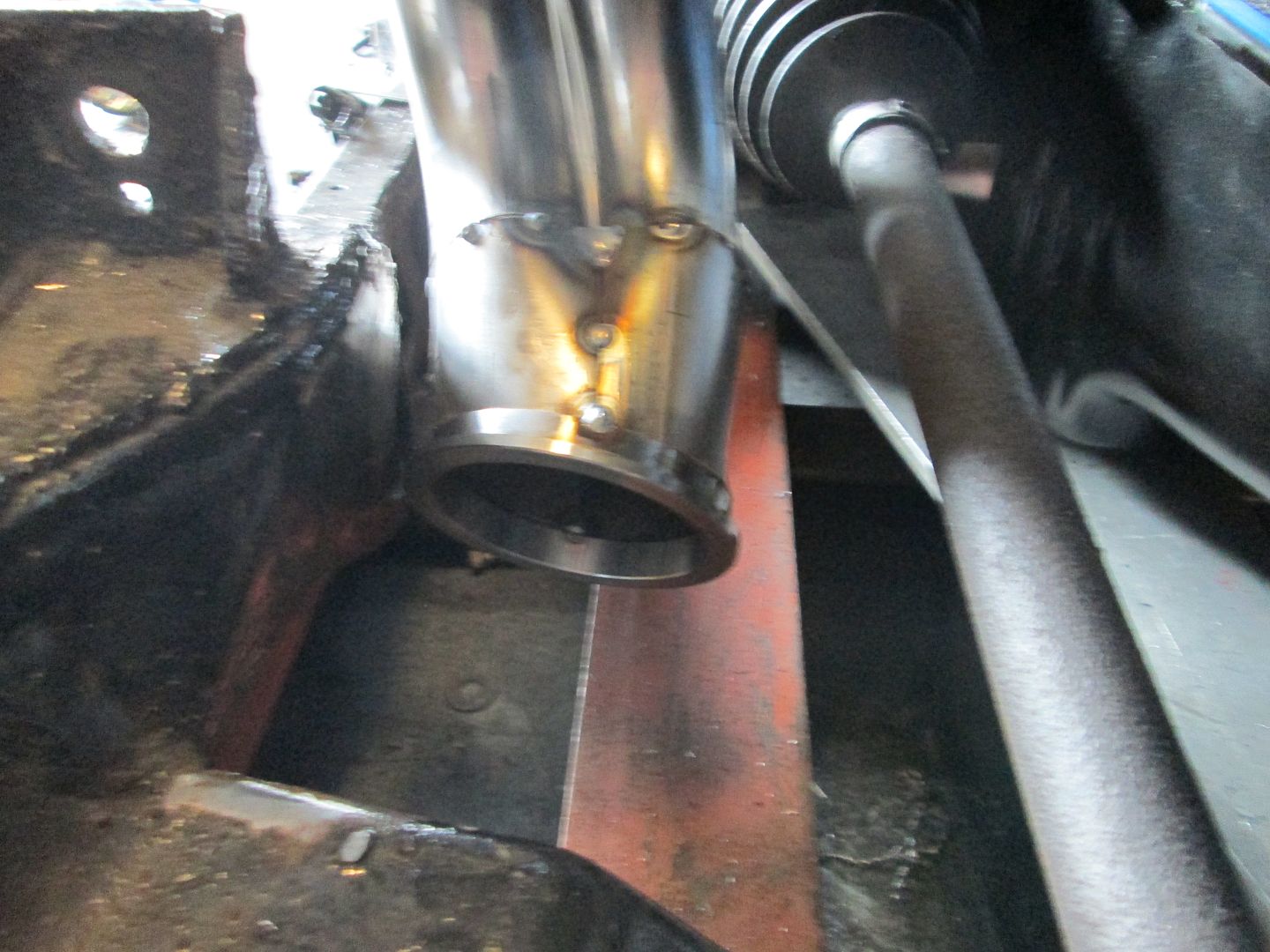
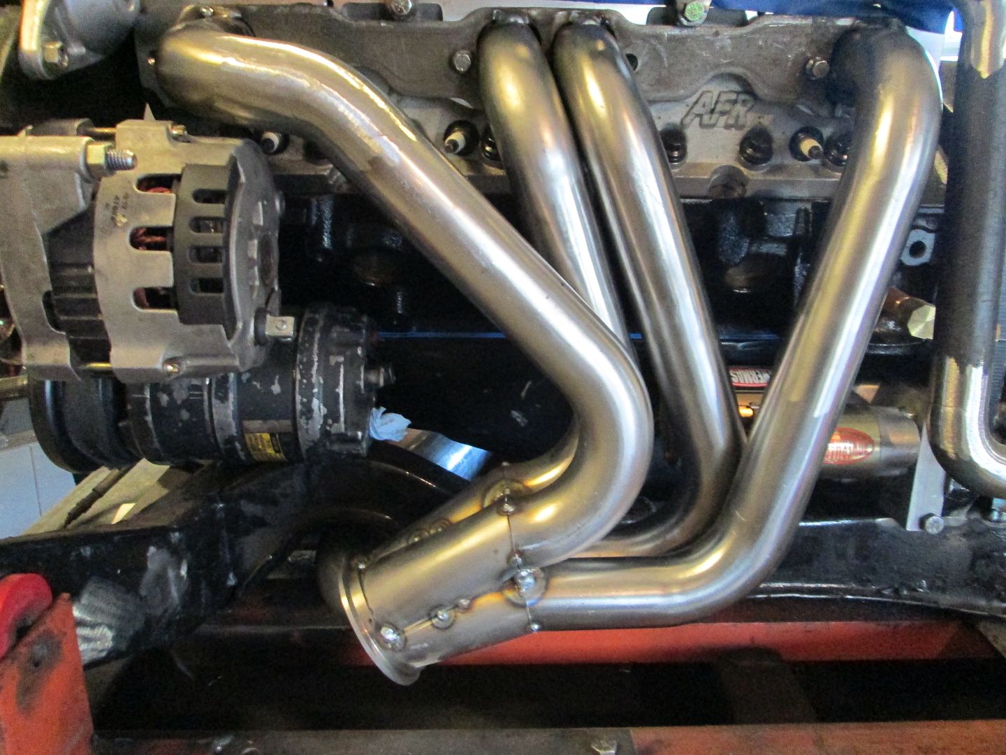
#7
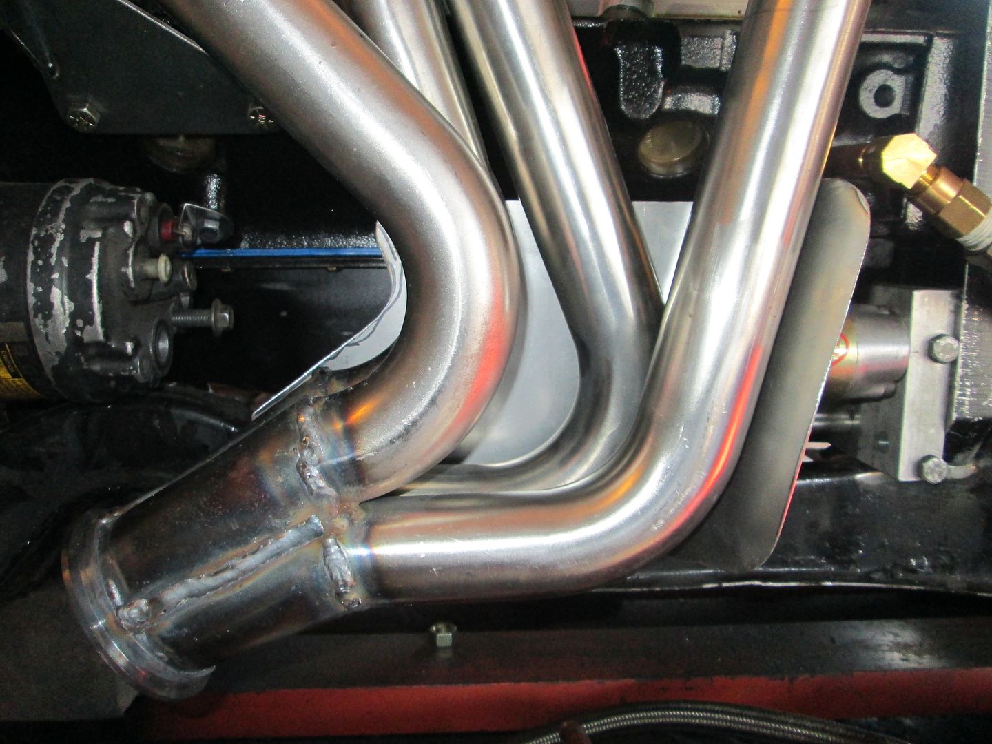
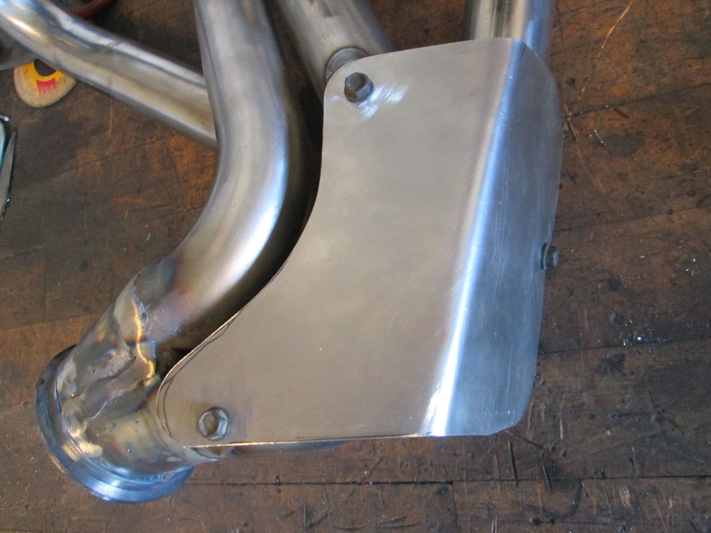
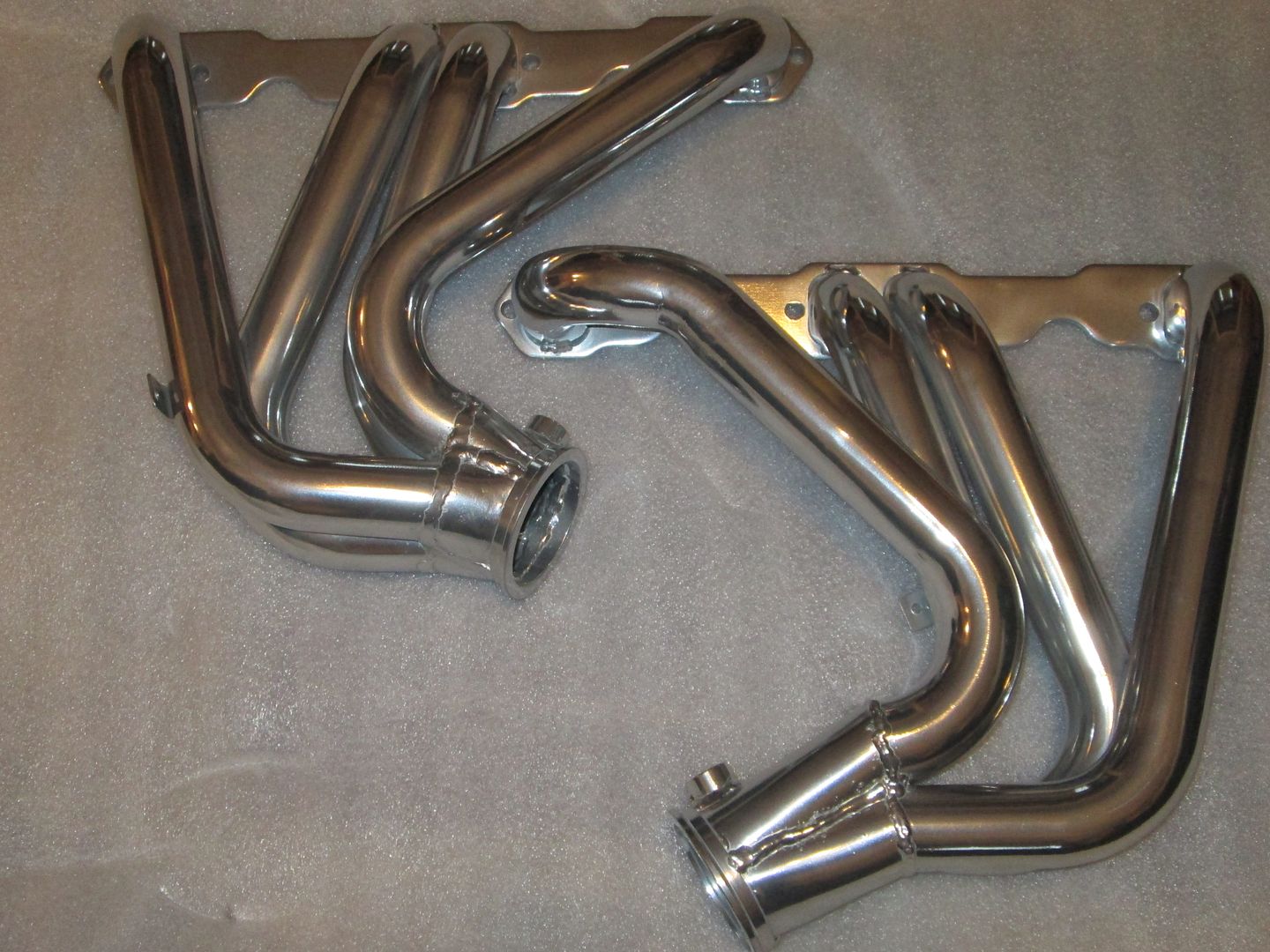
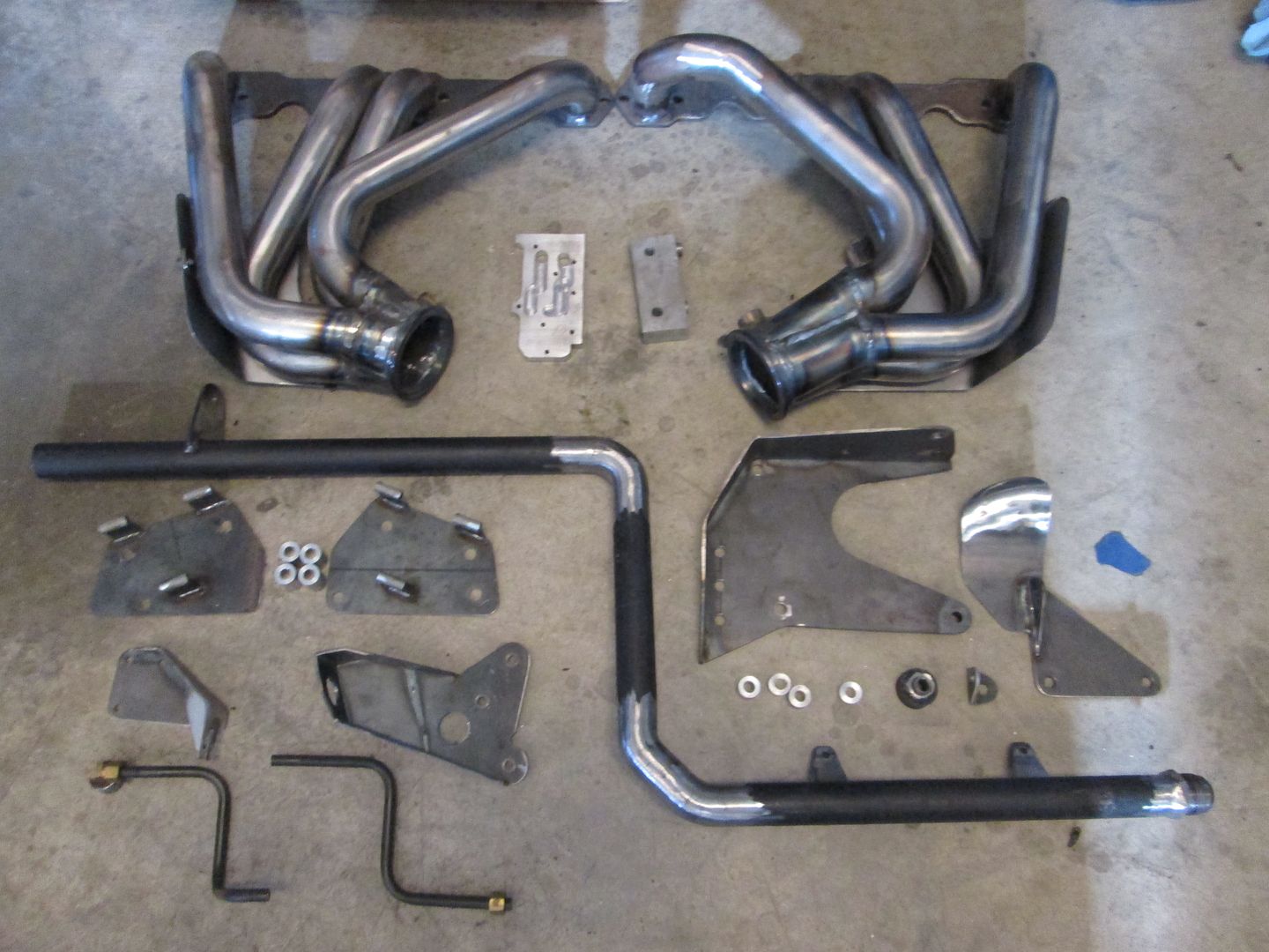
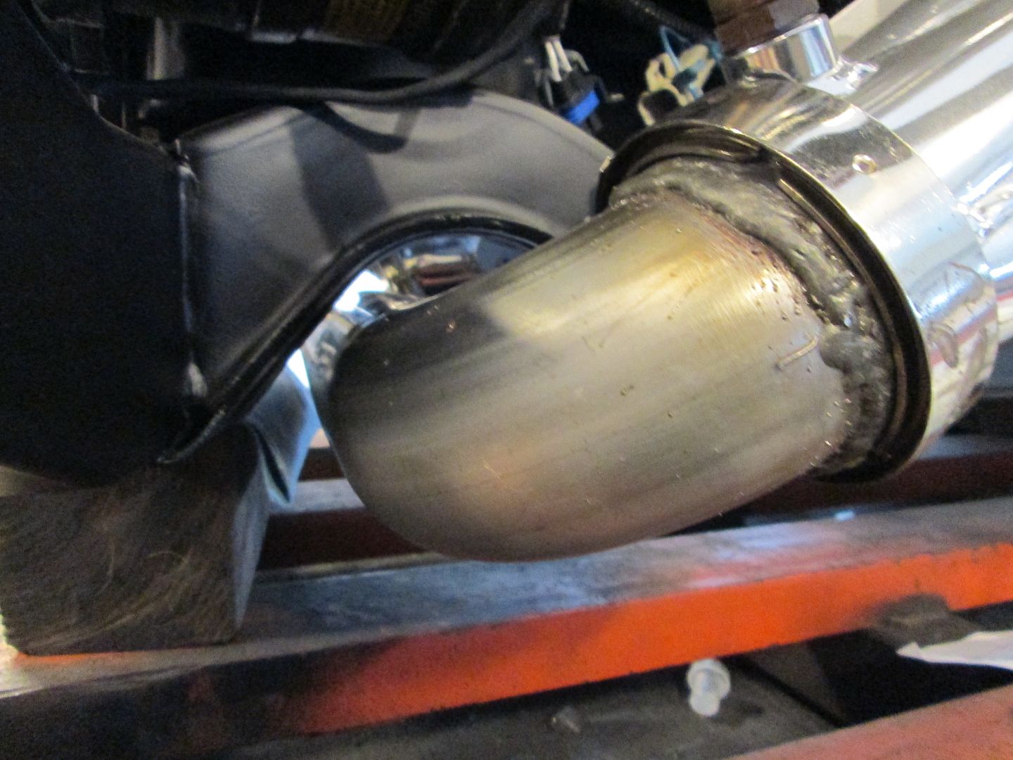
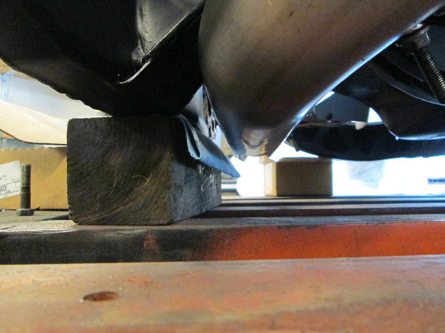
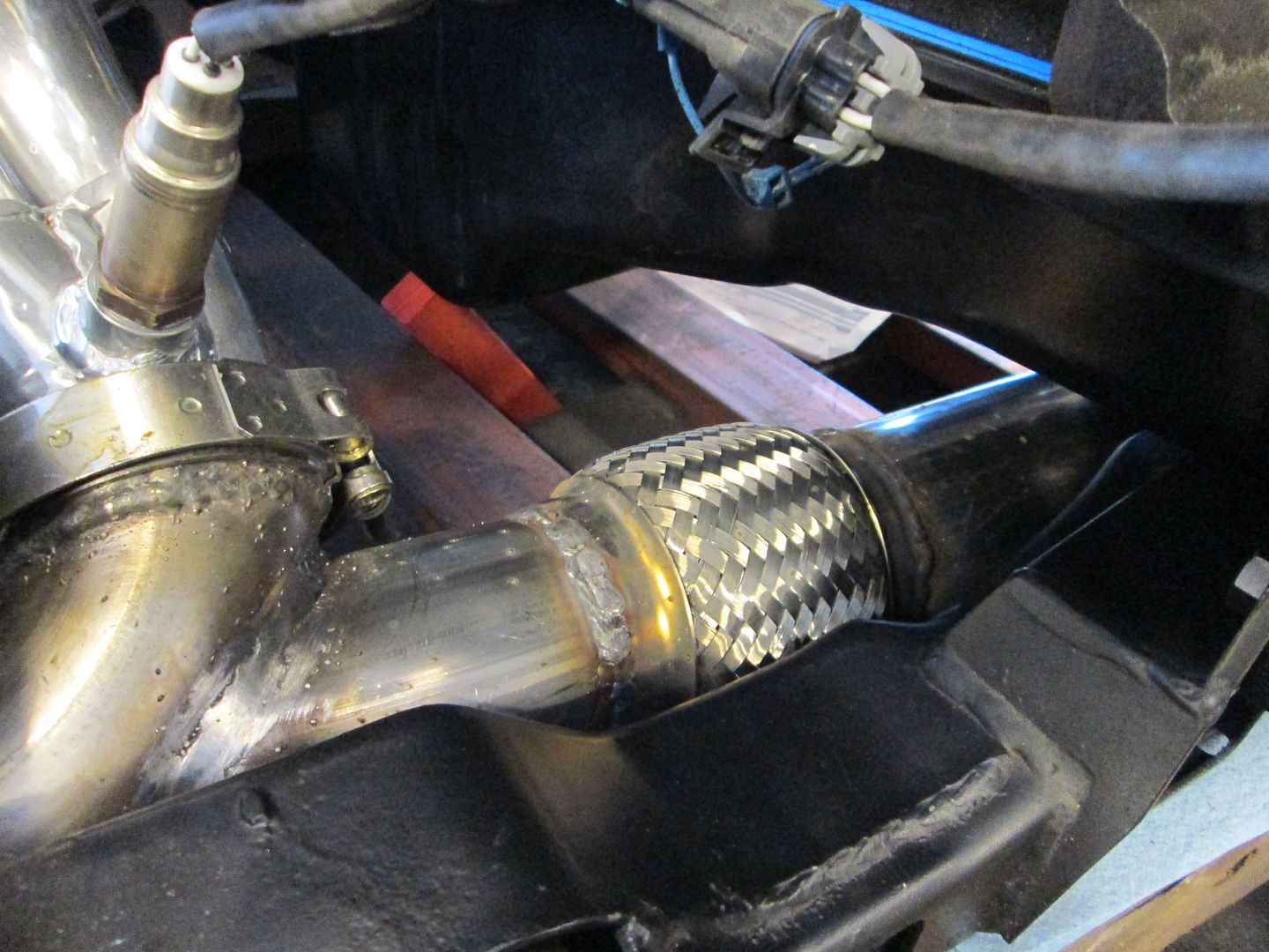
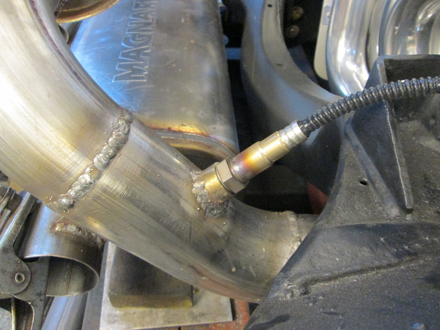
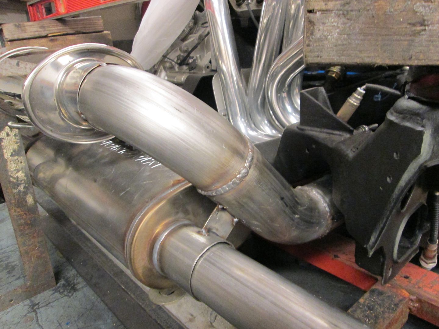
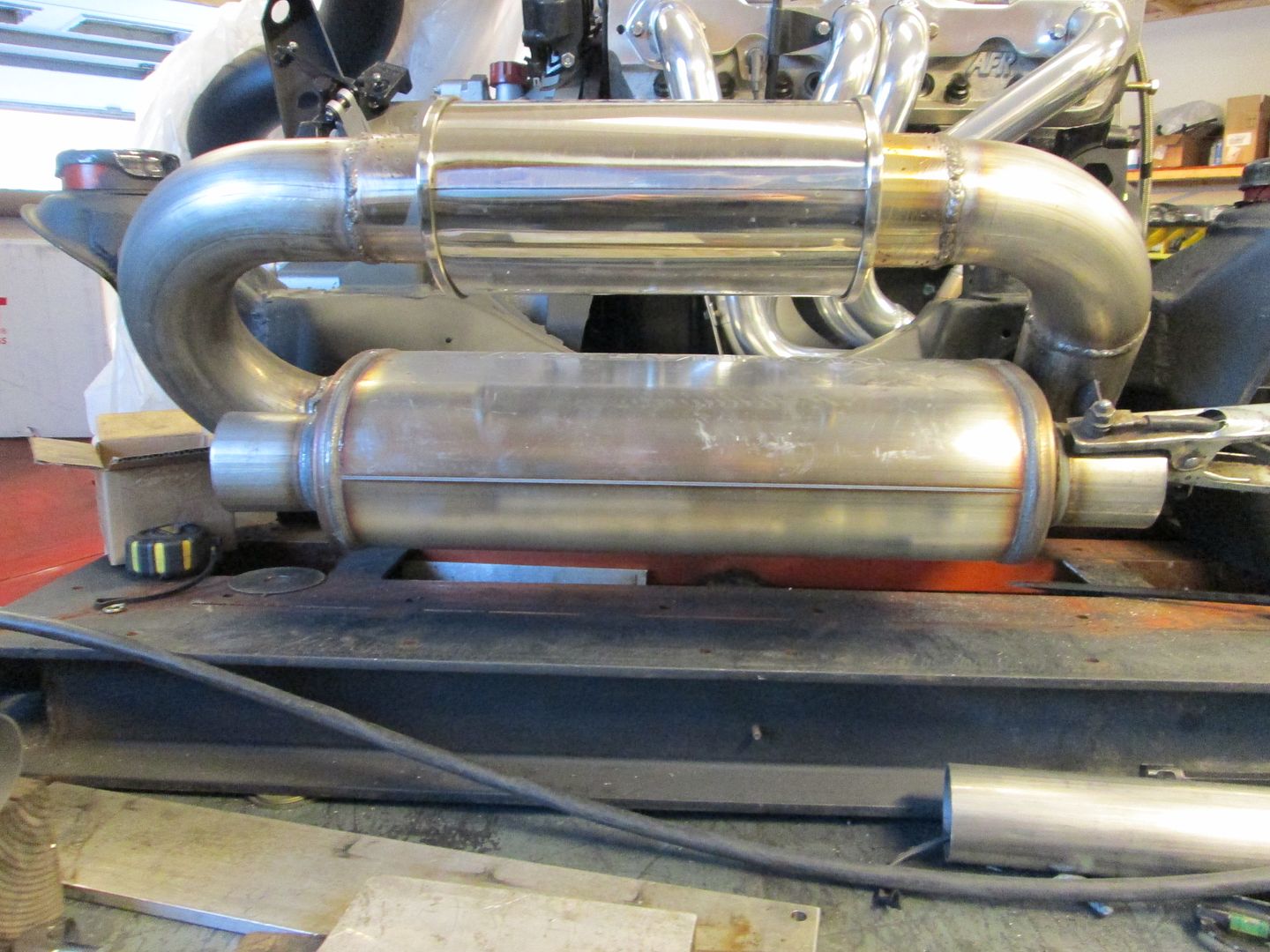
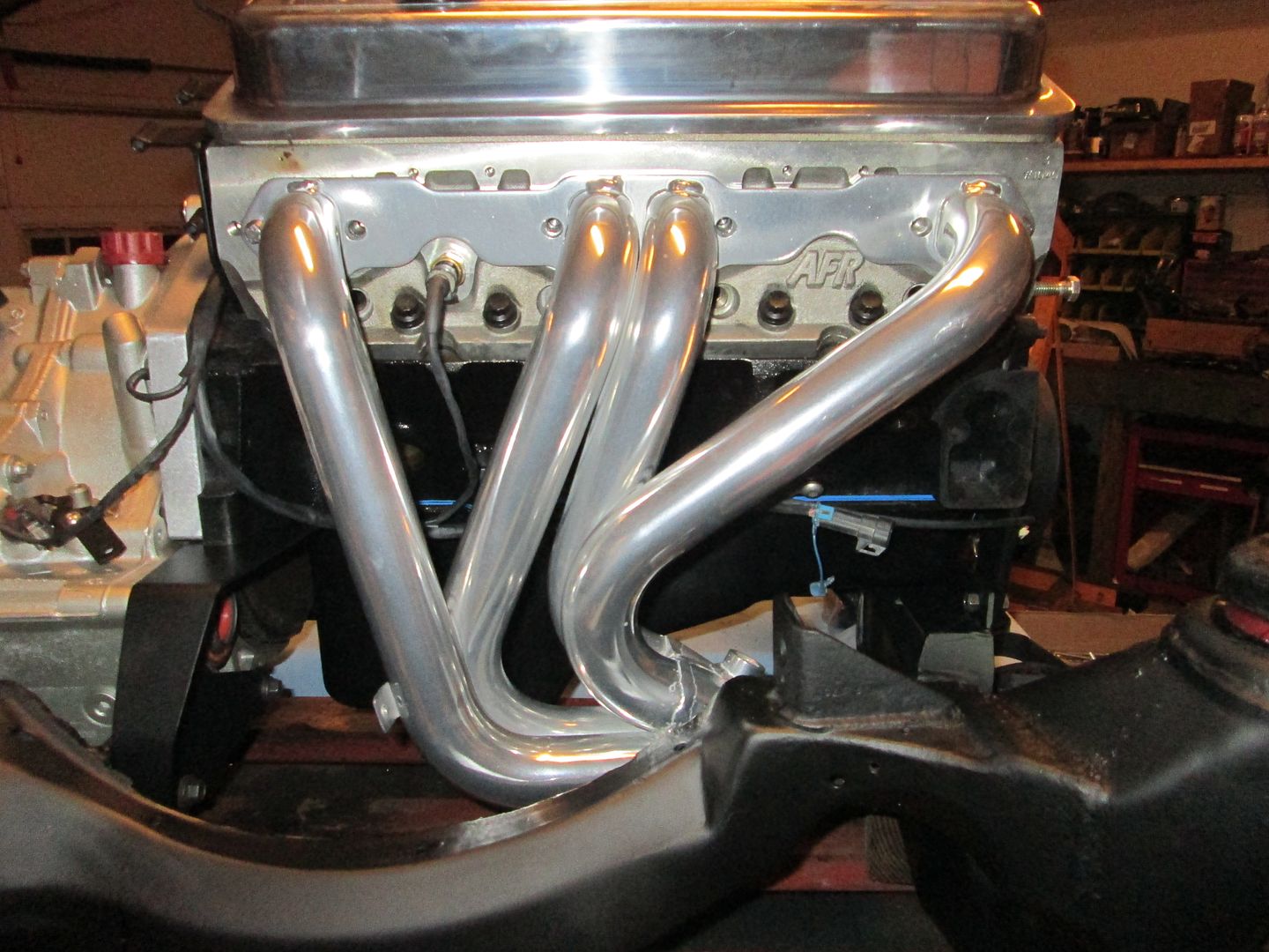
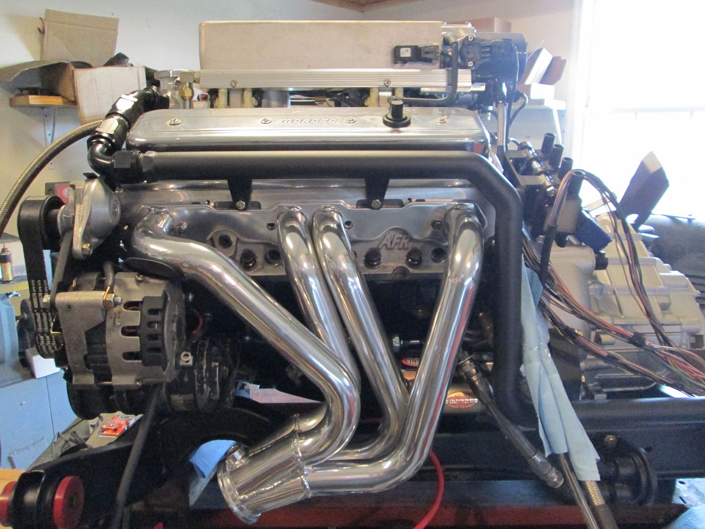
Its hard to get a good set of headers to fit a SBC in a Fiero. The short Sanderson ones normally crack after a few years and I wanted something longer. The profile of the forward swept open wheel headers looked promising, so I purchased a weld together kit and started trimming the pipes to make them fit the Fiero.
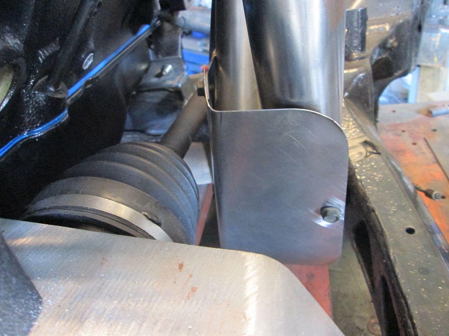
Heat shields were fabbed up to keep the heat off various other parts:
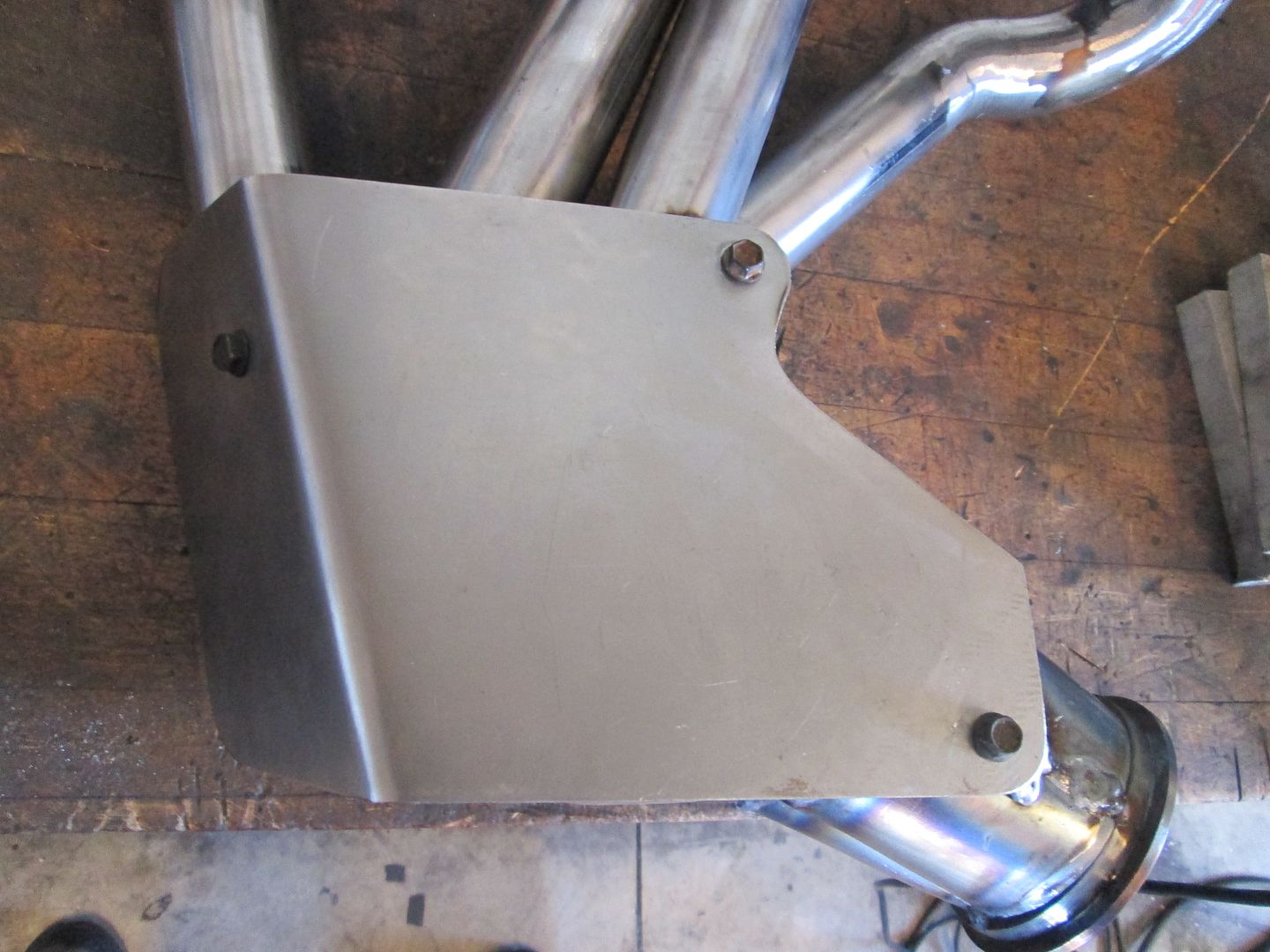
Back from Jet Hot:
Heat shields were fabbed up to keep the heat off various other parts:
Back from Jet Hot:
Last edited by fieroguru; 06-15-2014 at 05:04 PM.
Trending Topics
06-15-2014, 05:54 PM
#8
Moving on to the coolant system...
The Fiero coolant is filled from the rear, so I used a billet thermostat housing/fill point with a -16 AN fitting. From there a short section of stainless braided line will connect the two fittings:
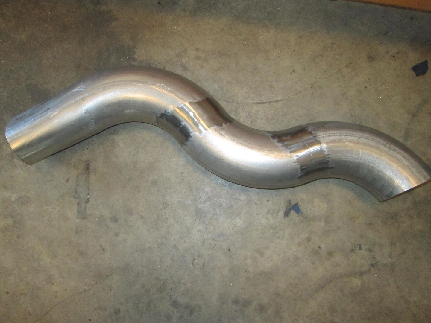
The rest of the coolant path from the thermostat will be hard line using schedule 40 1" pipe. I like it because the Fiero hoses attach right to it.
A stock threaded hole in the HSR intake was used for the heater hose. It will us AN fittings as well and braided stainless hose:
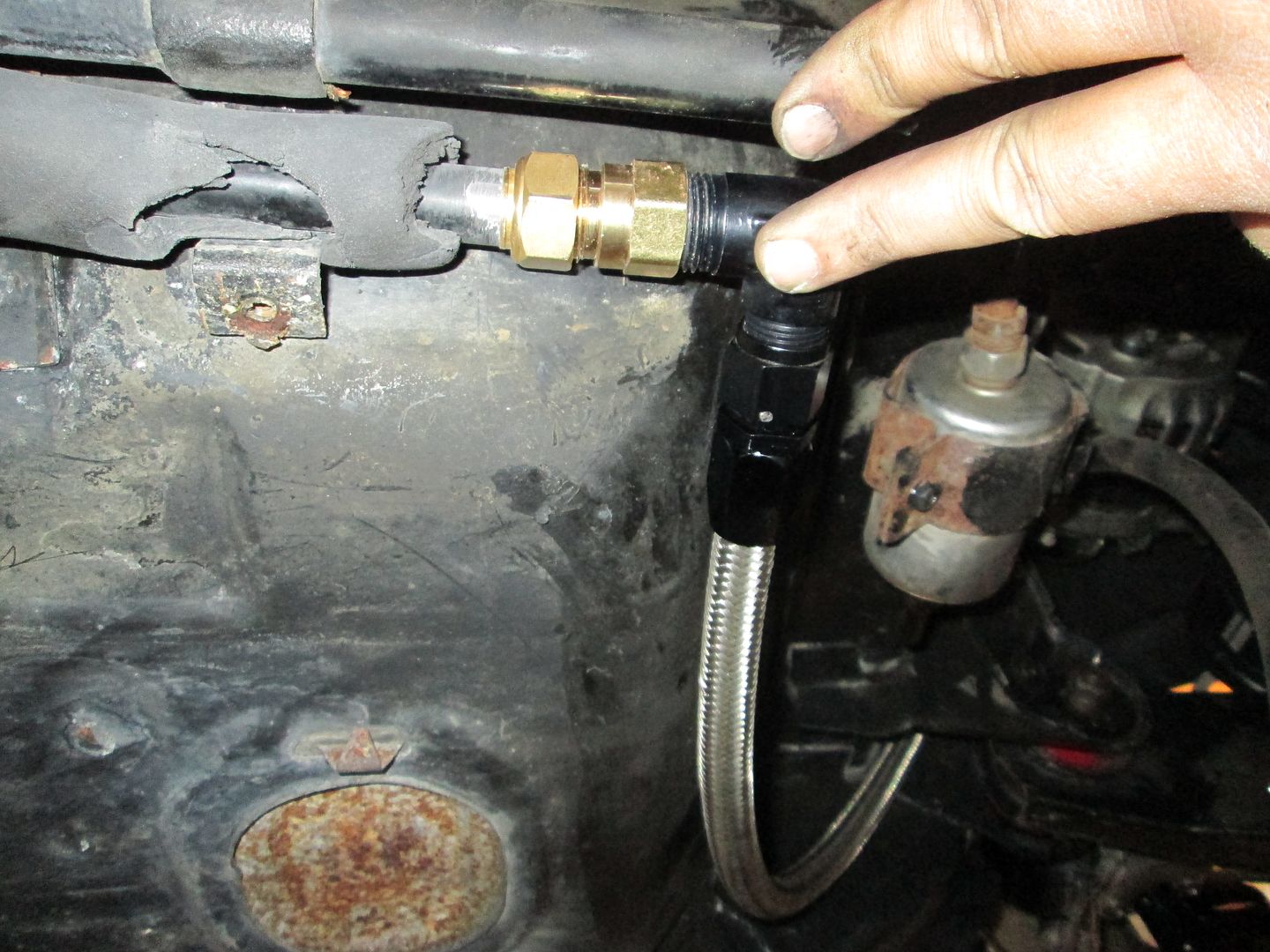
The other end of the heater hose connects to the stock hard line with a compression fitting:
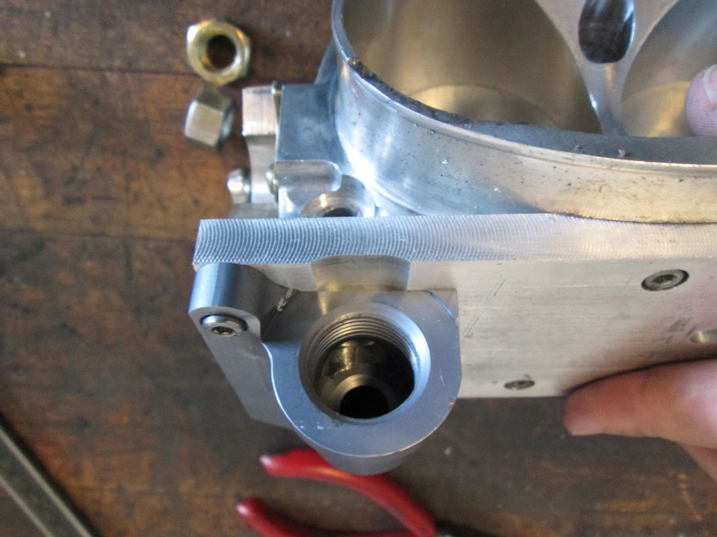
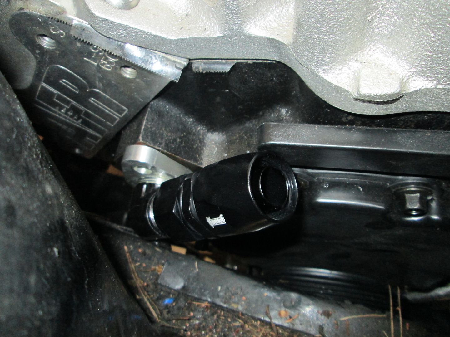
The coolant inlets to the engine were a very tight fit to the frame rail. I ended up making the plate thinner on one and threading one of the AN fittings deeper so it could be shorter:
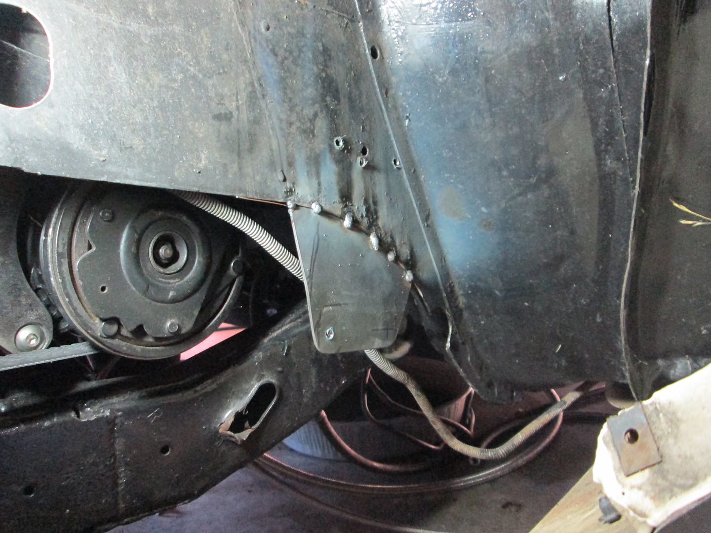
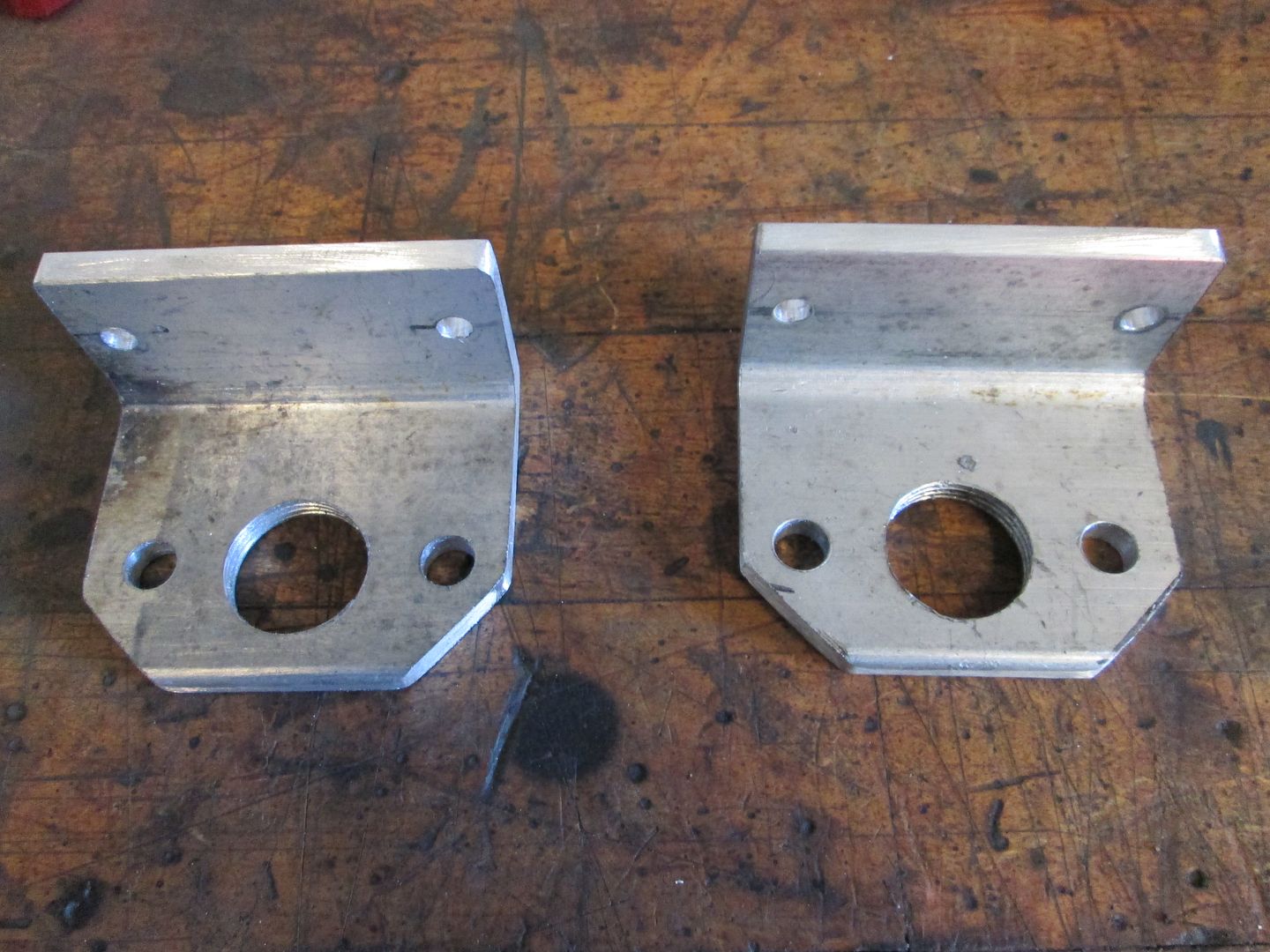
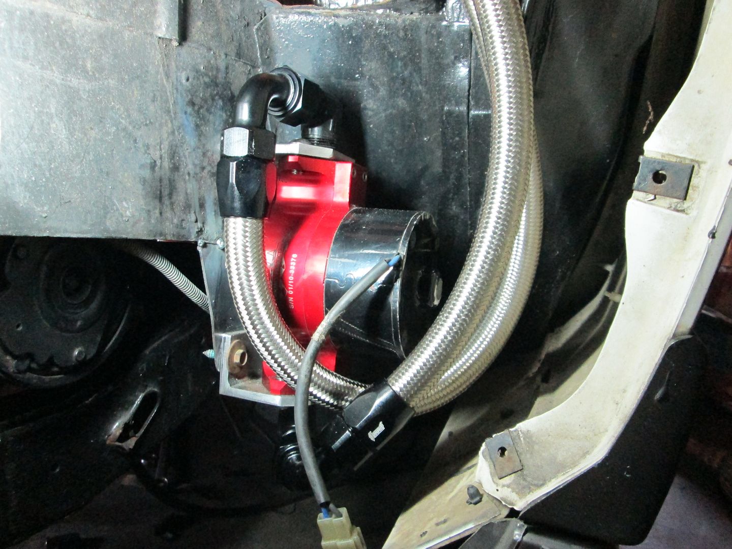
The water pump was remote mounted out of the engine bay. To support it I welded on a mounting plate and used some angle plates for the mounts (and to accept the AN fittings).

All the coolant hoses connected:
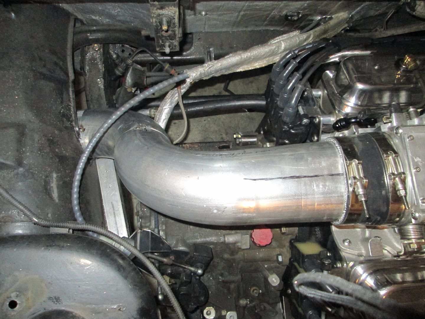
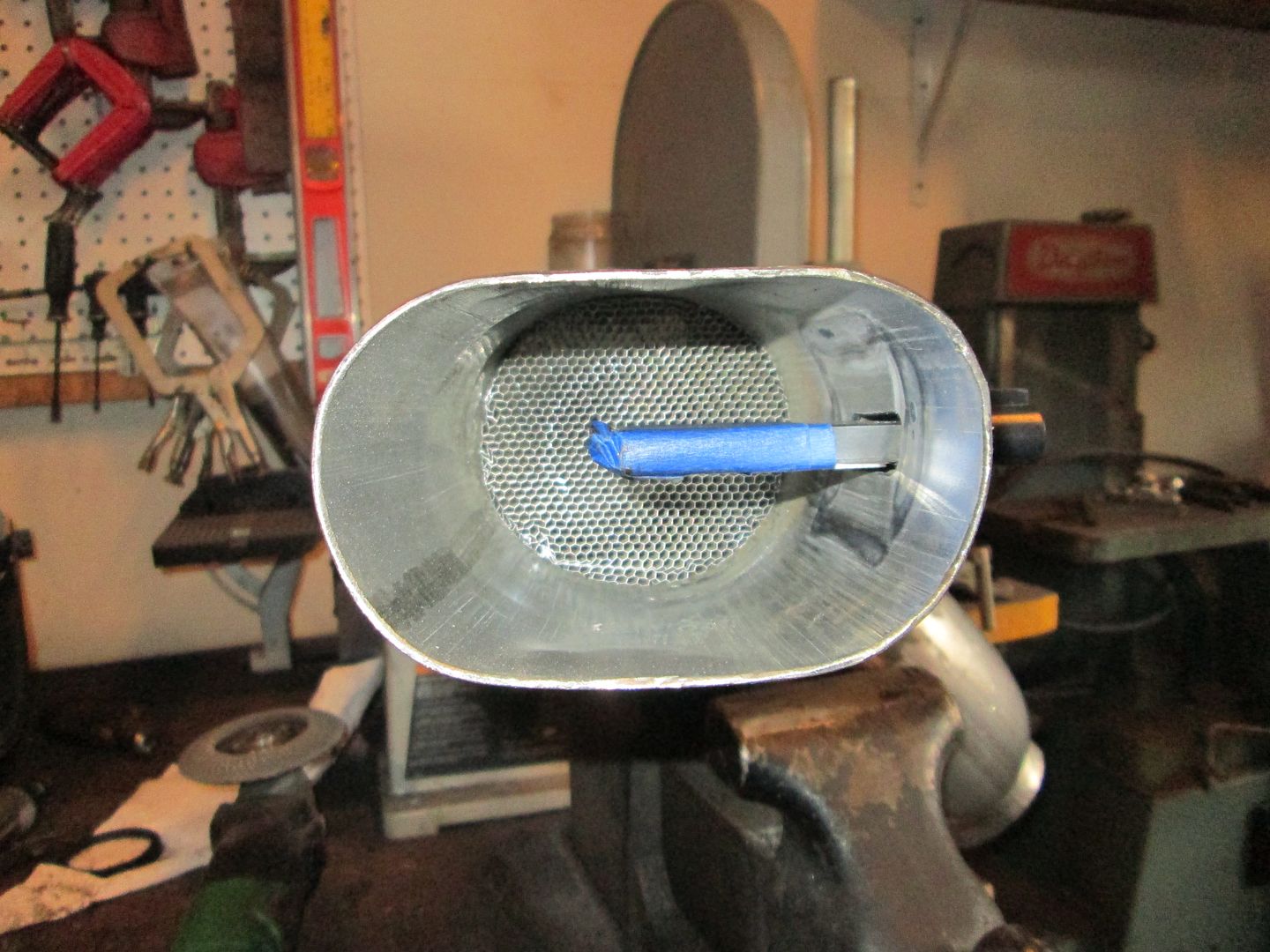
After the coolant system, I knocked out the cold air intake. I used some 4" exhaust tubing and ovaled one end to better transition to the throttle body. Also fabbed up a mount for the LS7 MAF sensor:

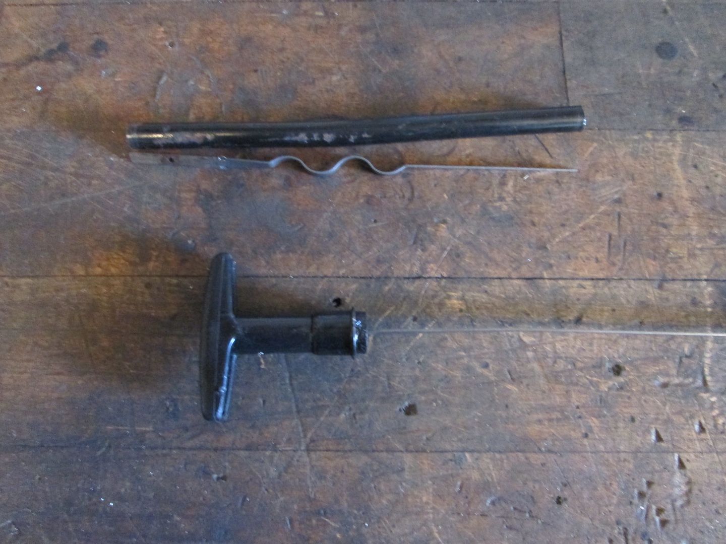
The oil dipstick was way too tall, so I shortened it as well and made a new mount for it:
The Fiero coolant is filled from the rear, so I used a billet thermostat housing/fill point with a -16 AN fitting. From there a short section of stainless braided line will connect the two fittings:
The rest of the coolant path from the thermostat will be hard line using schedule 40 1" pipe. I like it because the Fiero hoses attach right to it.
A stock threaded hole in the HSR intake was used for the heater hose. It will us AN fittings as well and braided stainless hose:
The other end of the heater hose connects to the stock hard line with a compression fitting:
The coolant inlets to the engine were a very tight fit to the frame rail. I ended up making the plate thinner on one and threading one of the AN fittings deeper so it could be shorter:
The water pump was remote mounted out of the engine bay. To support it I welded on a mounting plate and used some angle plates for the mounts (and to accept the AN fittings).
All the coolant hoses connected:
After the coolant system, I knocked out the cold air intake. I used some 4" exhaust tubing and ovaled one end to better transition to the throttle body. Also fabbed up a mount for the LS7 MAF sensor:
The oil dipstick was way too tall, so I shortened it as well and made a new mount for it:
06-15-2014, 06:04 PM
#9
We are nearing the end of the fabrication process... just a few more brackets to make.
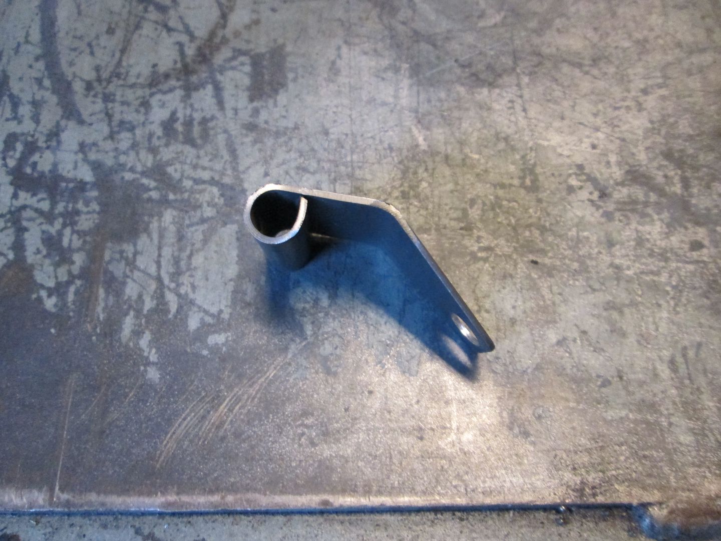
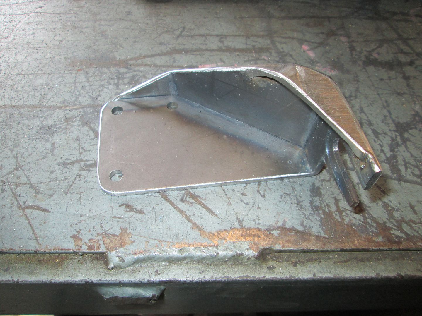
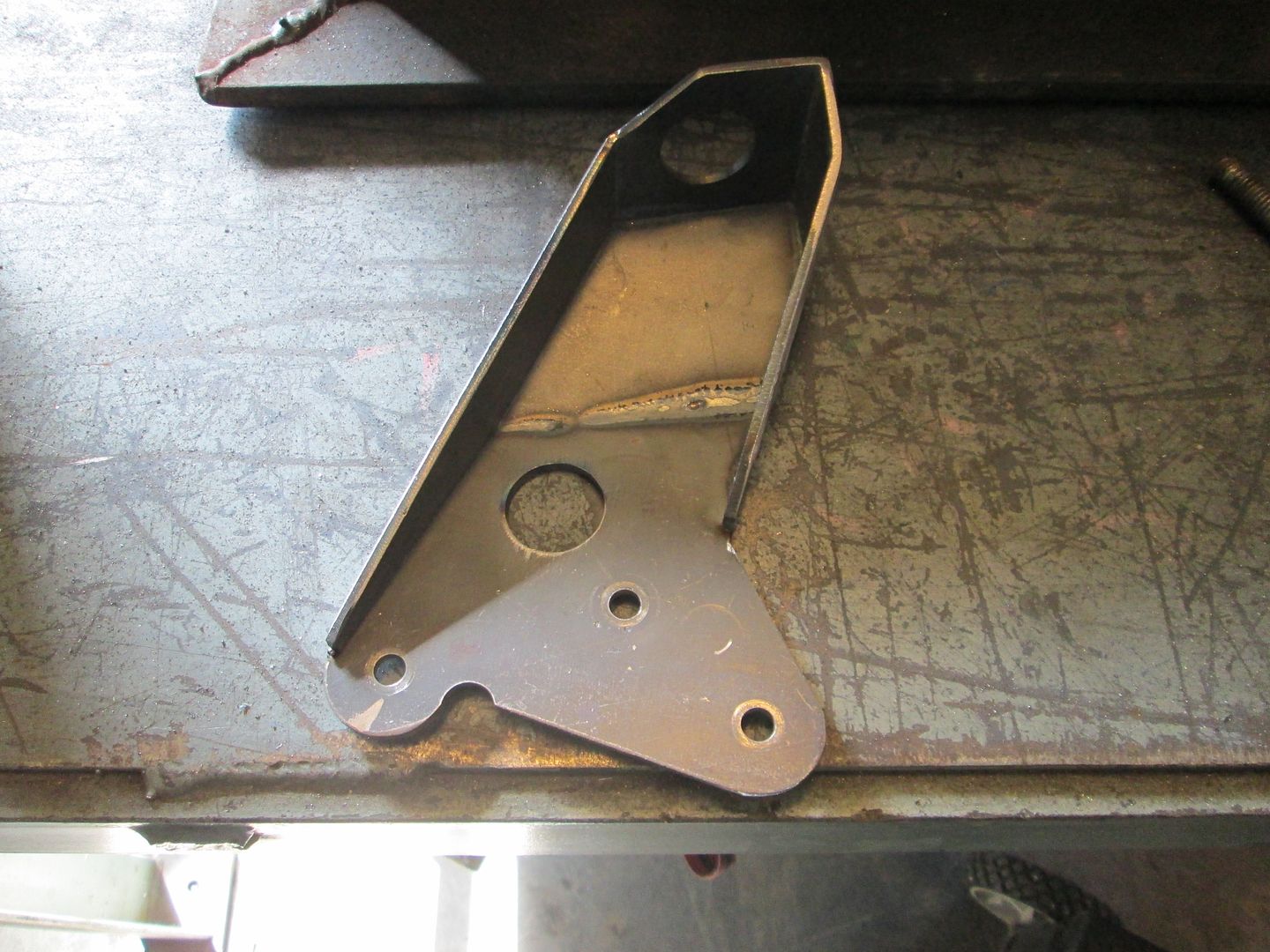
Throttle cable bracket to accept stock fiero throttle cable. It was made from several pieces of 1/8" steel:
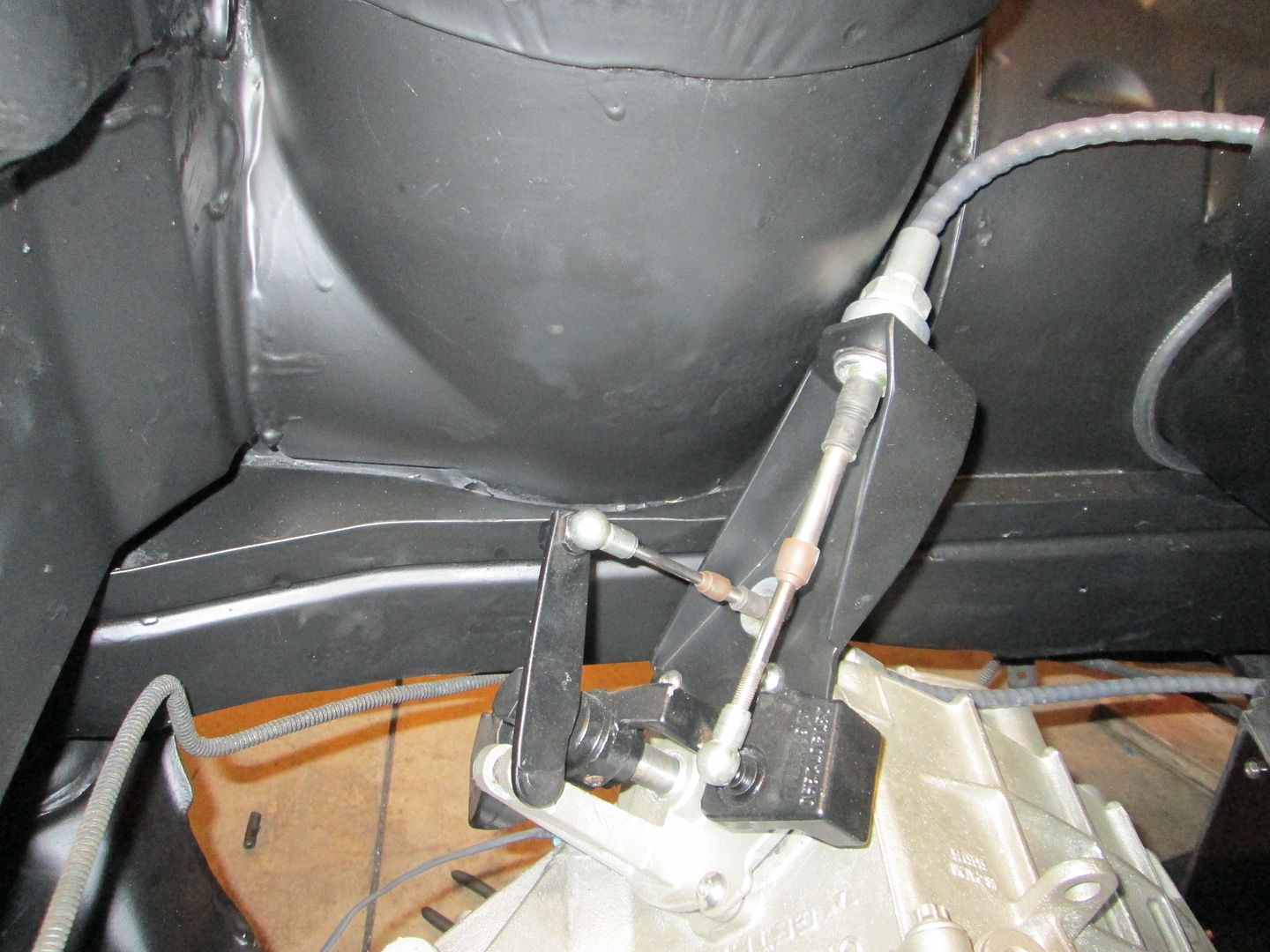
Transmission shift cable bracket (the old one didn't have the geometry right). Also fabbed from 1/8" plate:
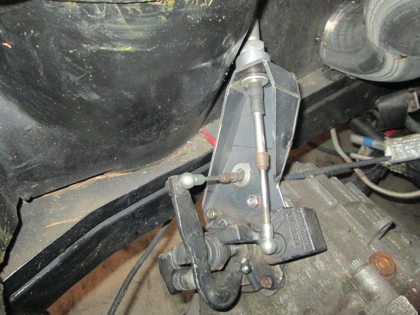
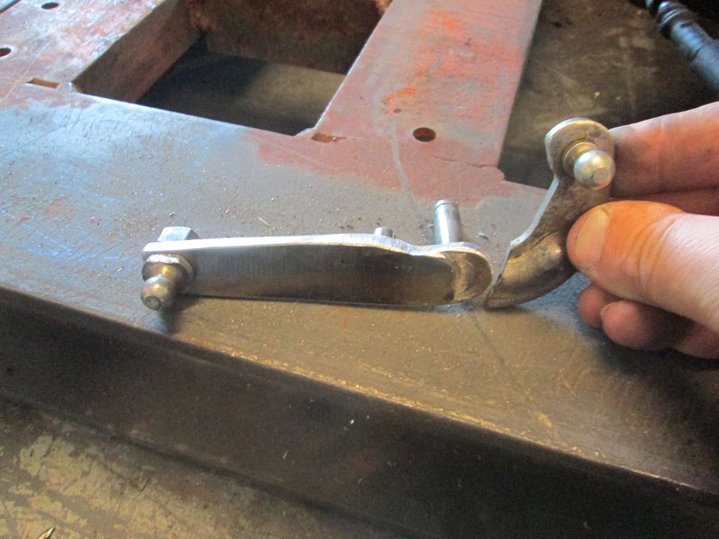
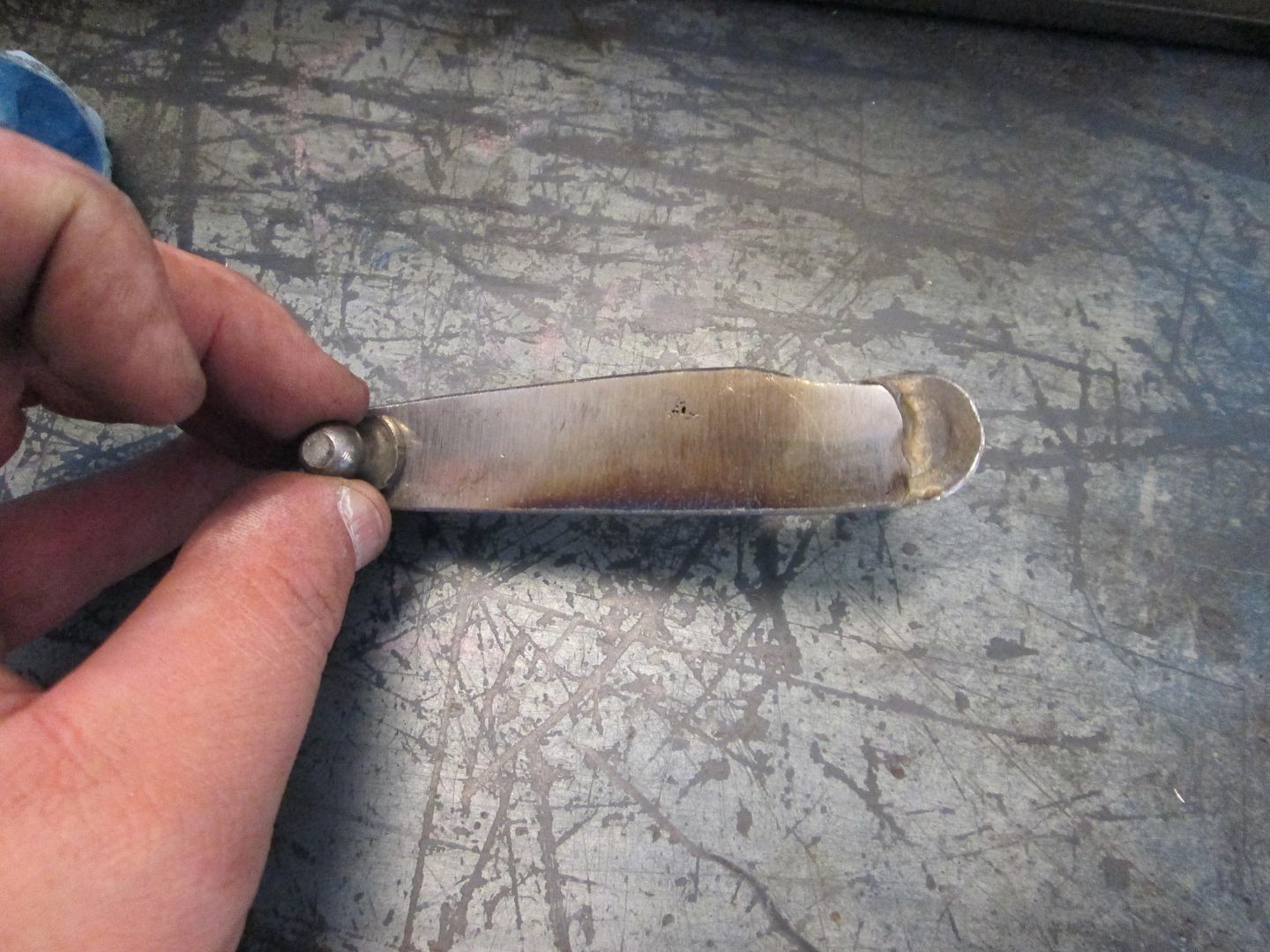
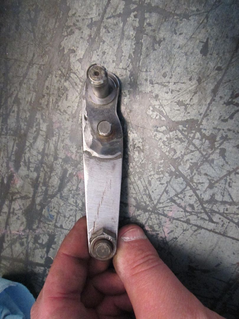
Also cut and cleaned up the shift lever that mounts to the transmission. This had the long extension welded to it to adapt the FWD transmission to the Fiero, but the curved portion was not needed.
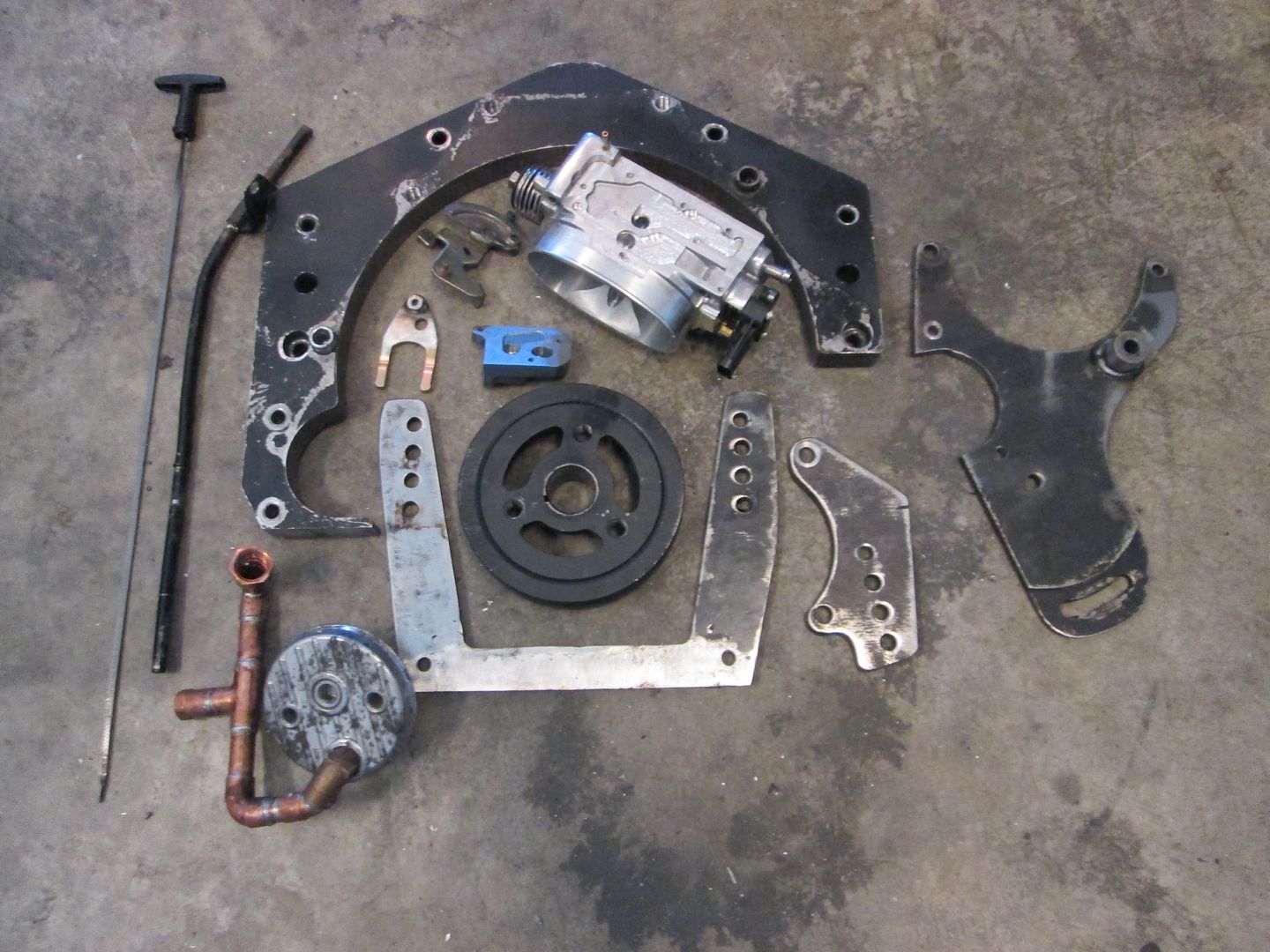
Here are almost all the parts for this swap that were either made or modified (cold air intake and cradle are not shown):
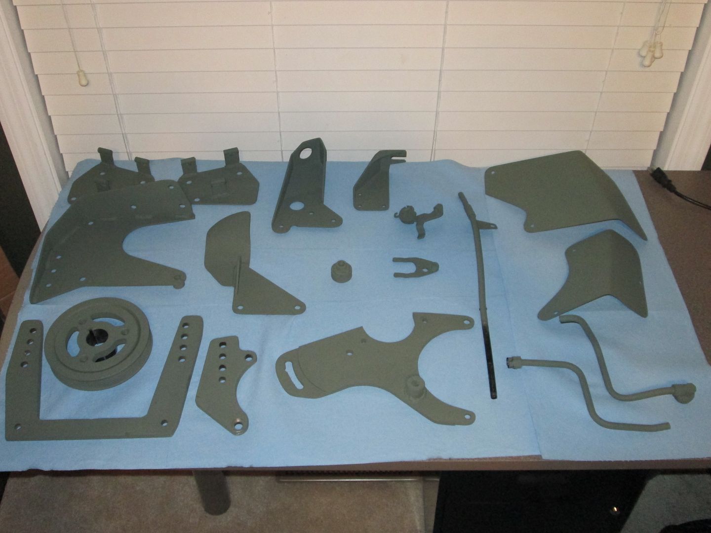
Here are some of the parts in primer:
Throttle cable bracket to accept stock fiero throttle cable. It was made from several pieces of 1/8" steel:
Transmission shift cable bracket (the old one didn't have the geometry right). Also fabbed from 1/8" plate:
Also cut and cleaned up the shift lever that mounts to the transmission. This had the long extension welded to it to adapt the FWD transmission to the Fiero, but the curved portion was not needed.
Here are almost all the parts for this swap that were either made or modified (cold air intake and cradle are not shown):
Here are some of the parts in primer:
06-15-2014, 06:18 PM
#10
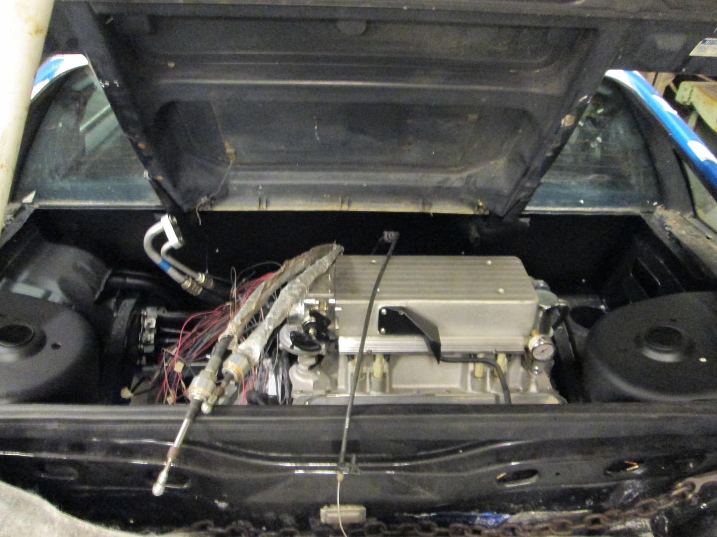
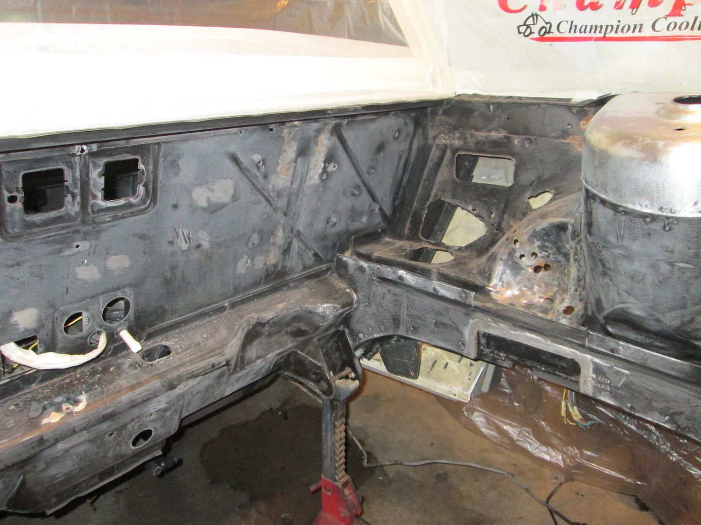
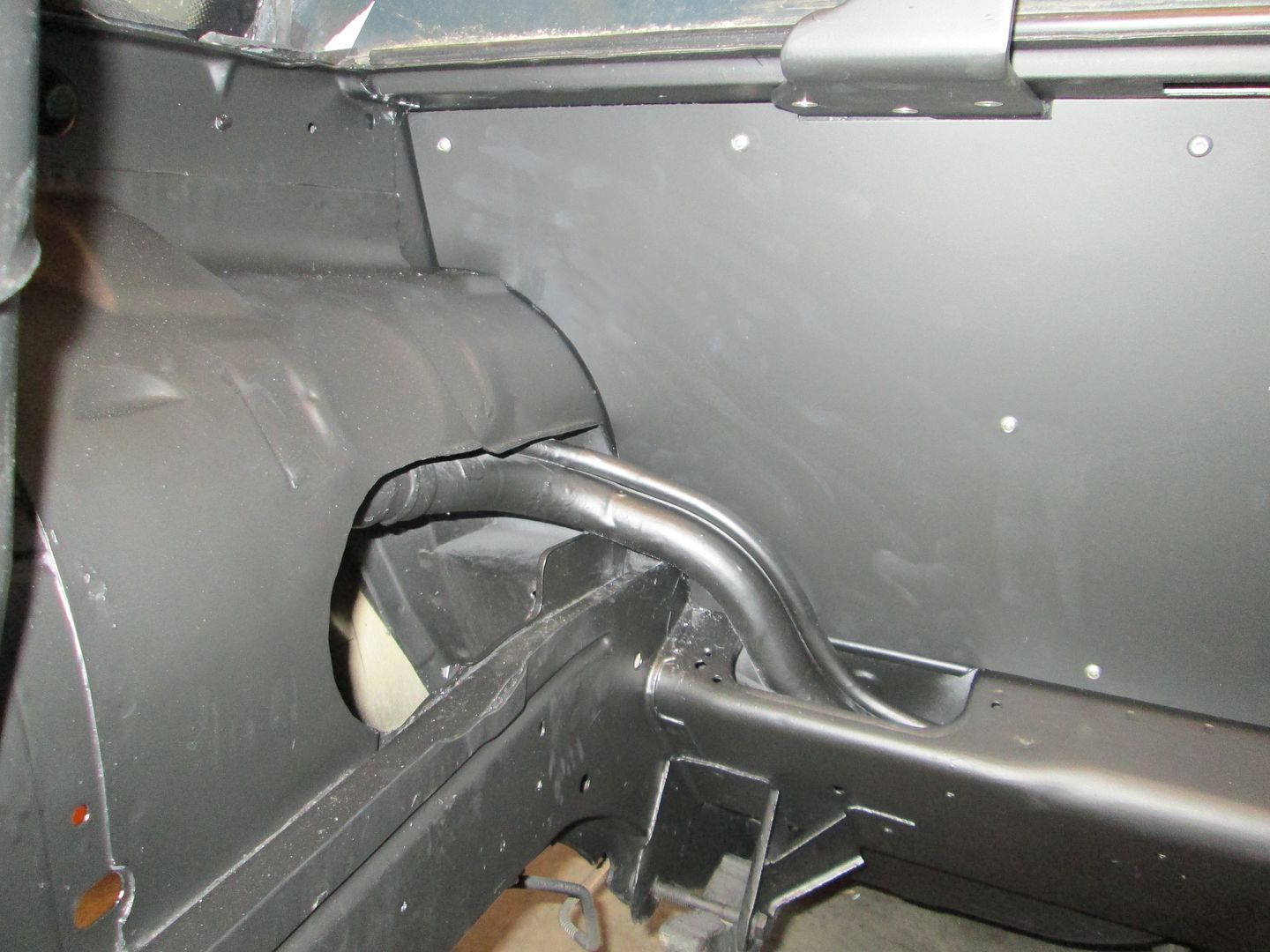
Now it was time to start cleaning up the engine bay.
If it wasn't needed, it was removed:
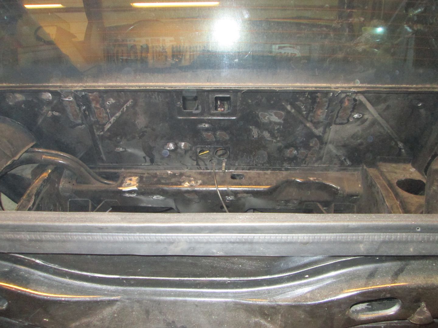
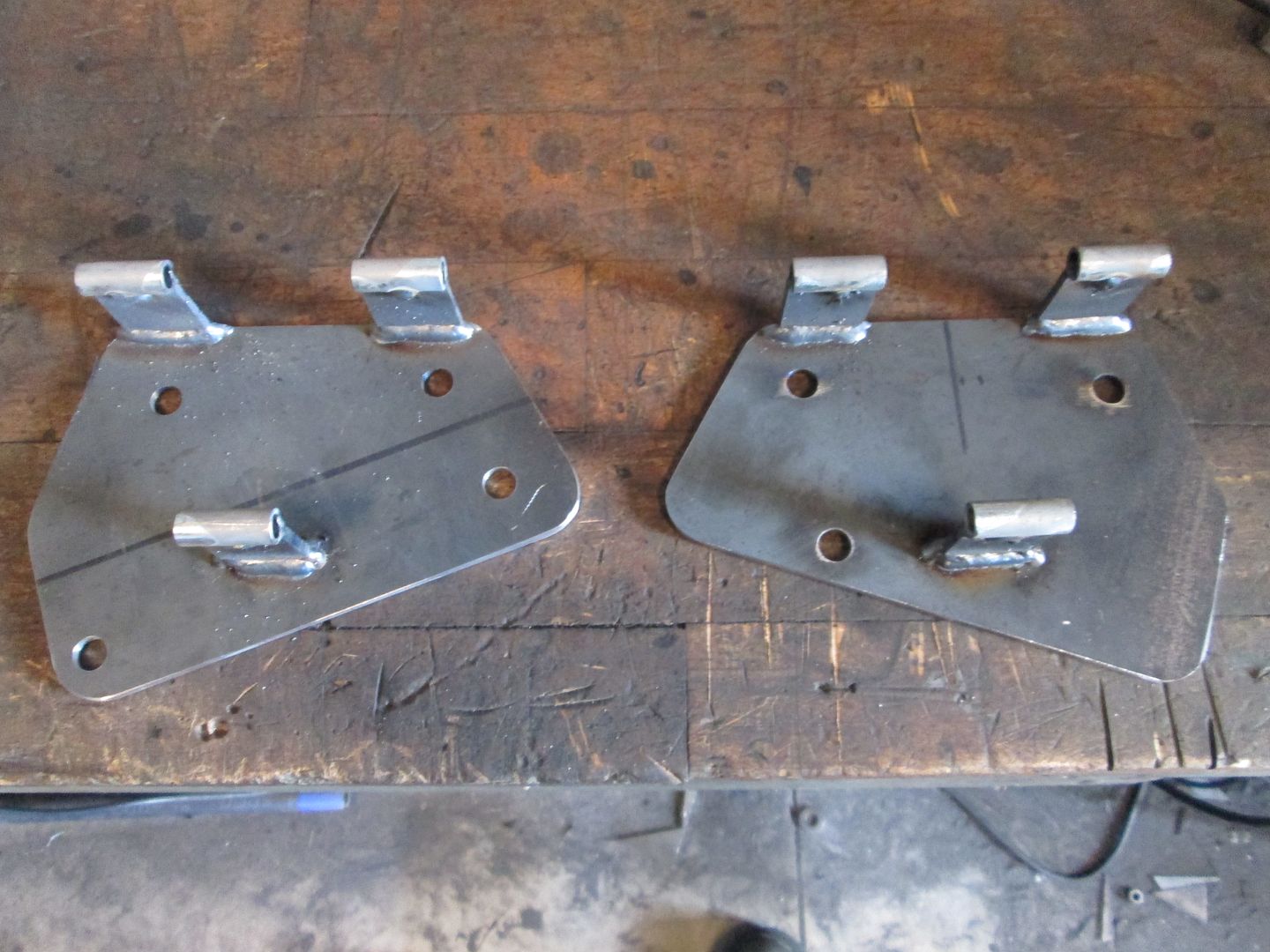
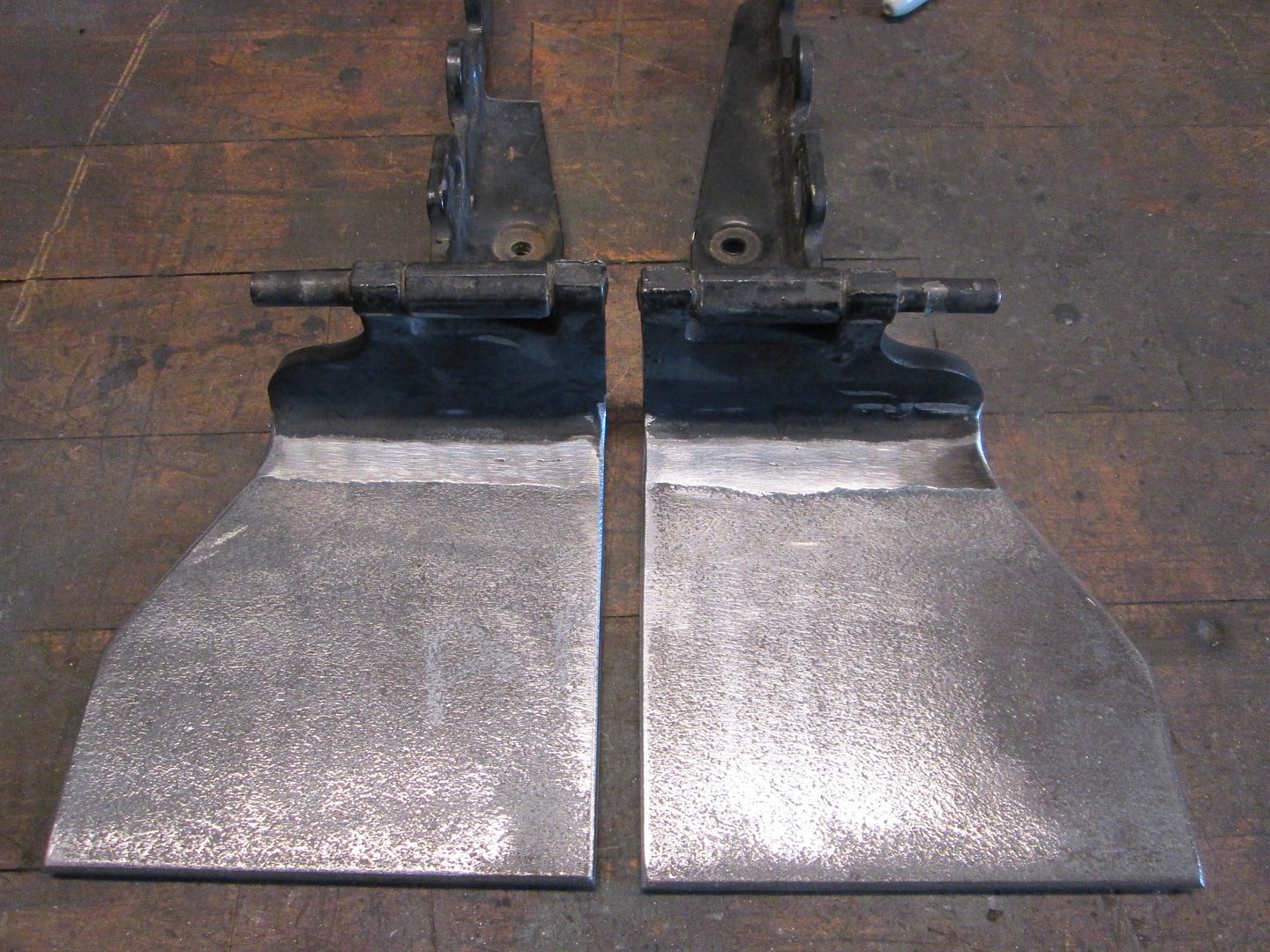
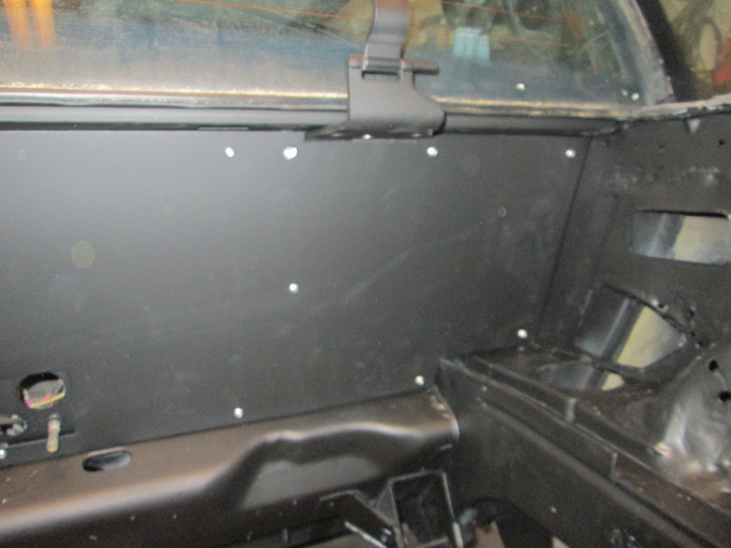
The decklid hinge boxes were removed and new hinge mounts welded to the factory hinges:
A spreader bar was slid into place for the new hinges to mount to:
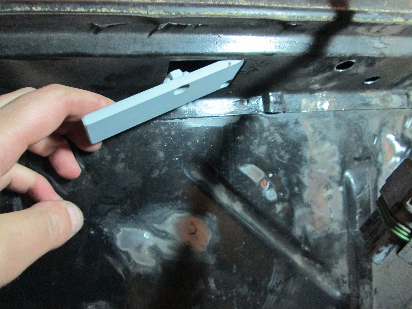
Additional support leg added to hinges to stiffen them up some:
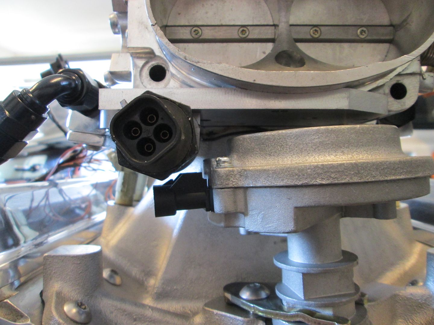
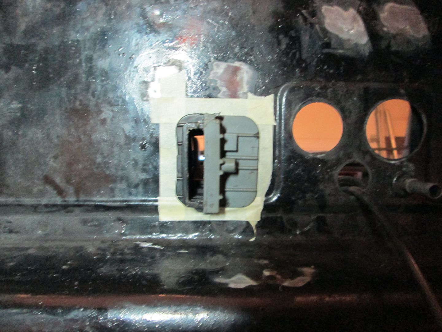
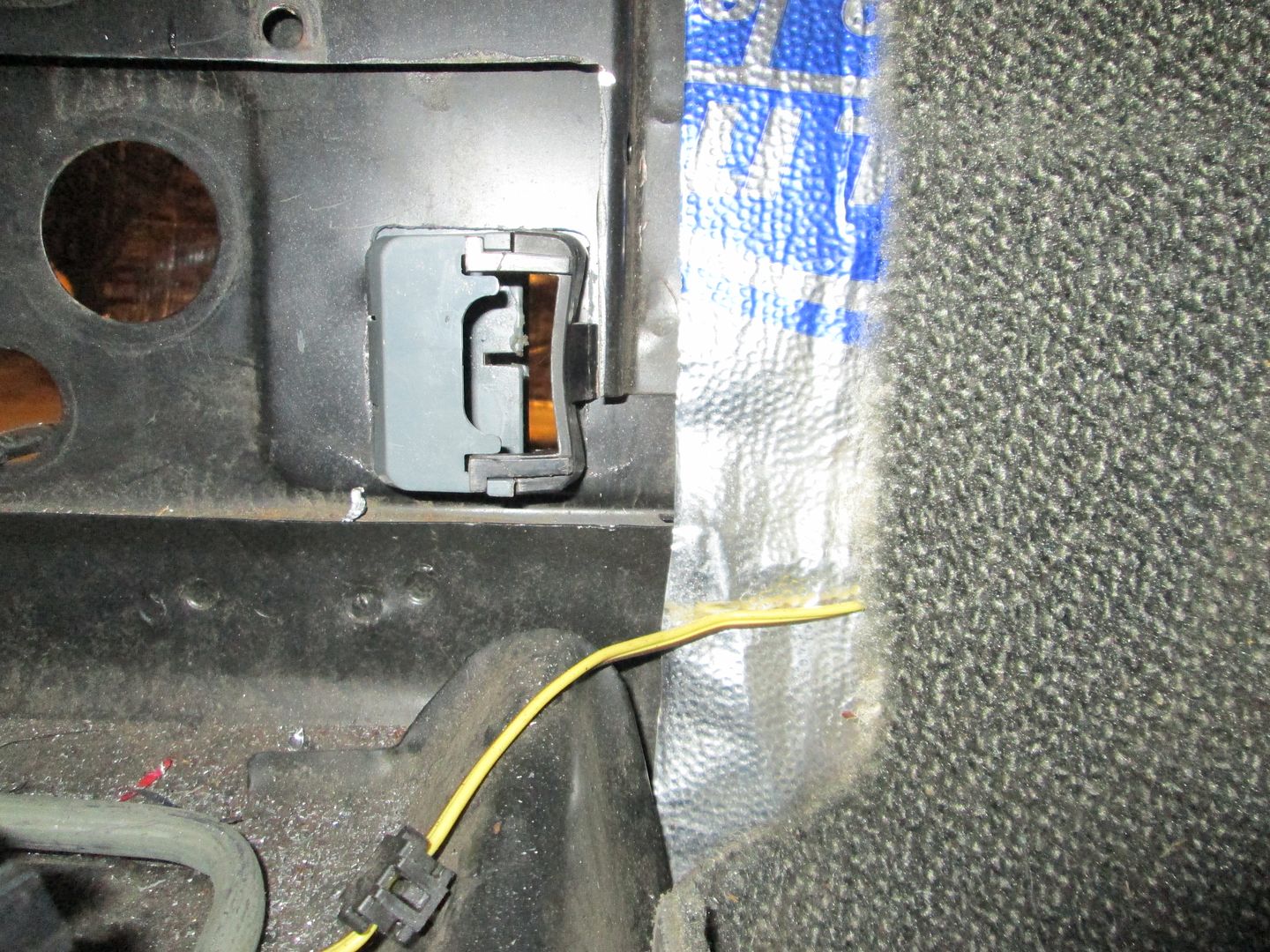
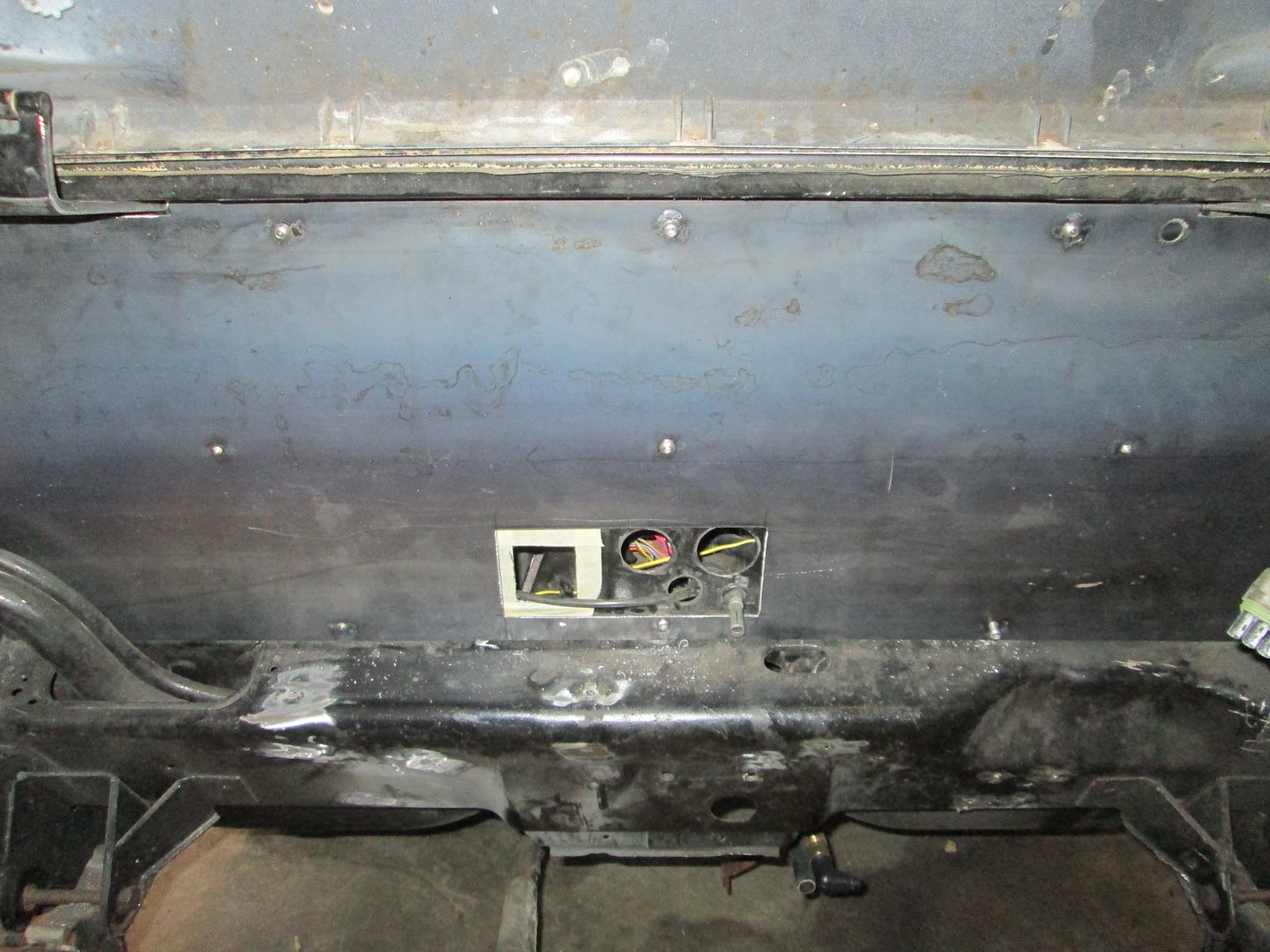
Wiring pass through connector relocated down low where it will not be as visible:
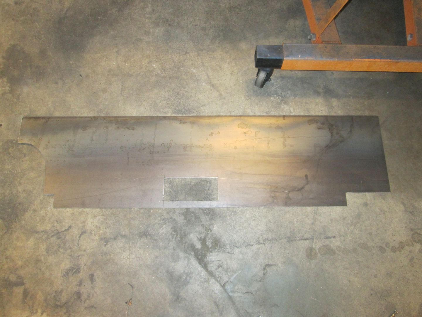
Smooth firewall panel cut to size:
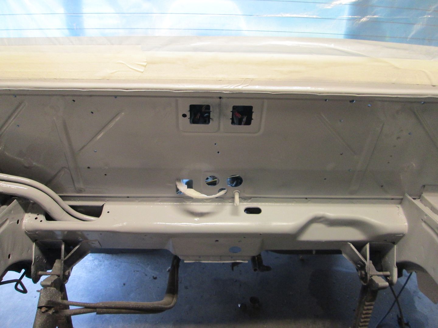
Prep engine bay for paint:
Primed:
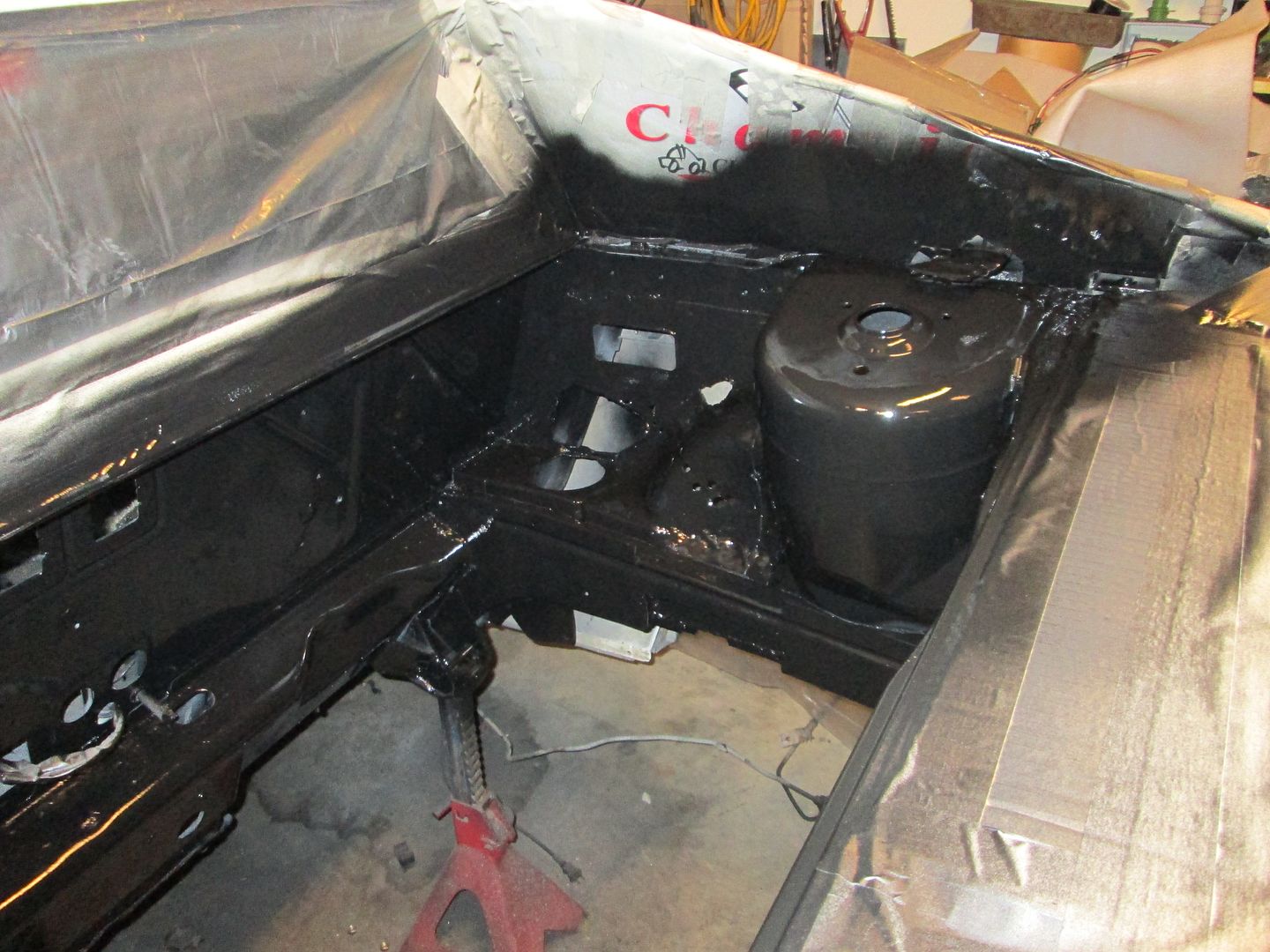
Painted:
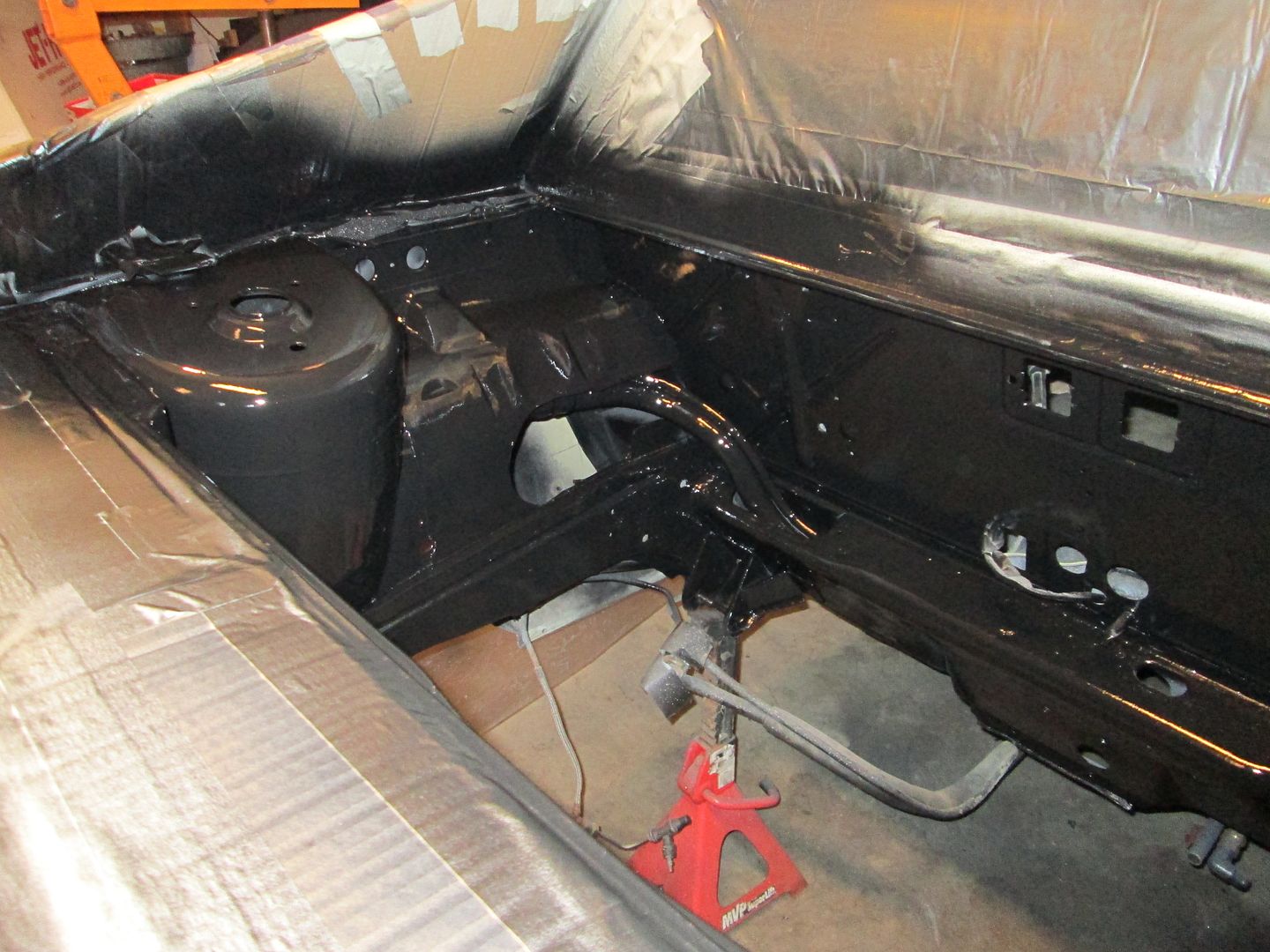
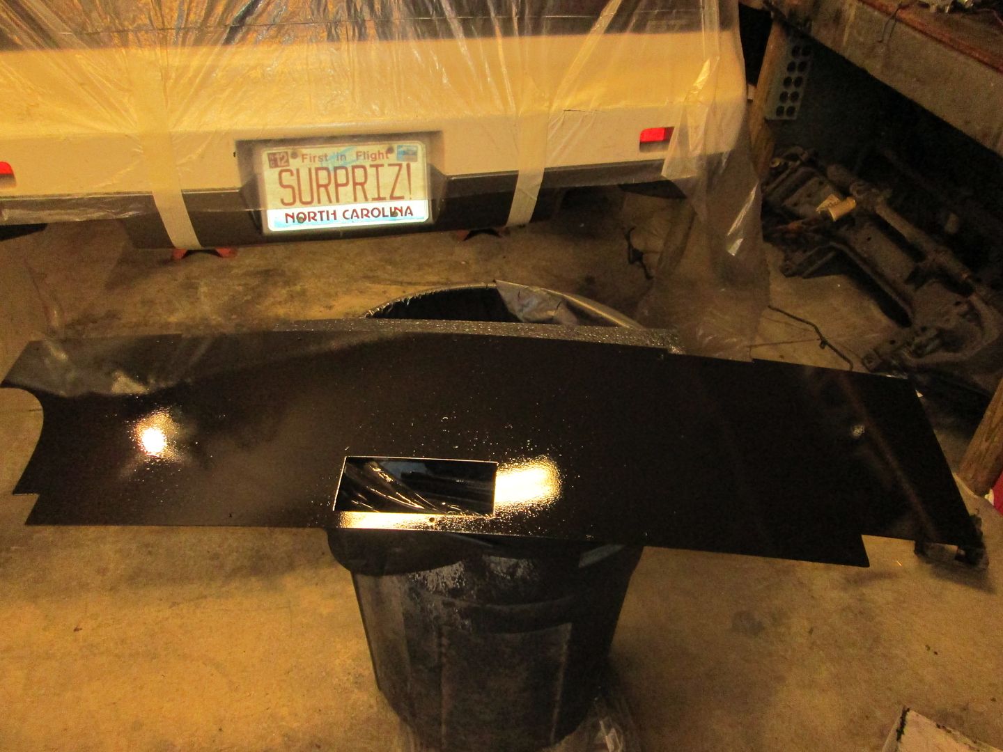
Painted smooth firewall panel installed:
If it wasn't needed, it was removed:
The decklid hinge boxes were removed and new hinge mounts welded to the factory hinges:
A spreader bar was slid into place for the new hinges to mount to:
Additional support leg added to hinges to stiffen them up some:
Wiring pass through connector relocated down low where it will not be as visible:
Smooth firewall panel cut to size:
Prep engine bay for paint:
Primed:
Painted:
Painted smooth firewall panel installed:
 06-18-2014, 05:19 PM
#14
Teching In
Join Date: Aug 2013
Posts: 36
Likes: 0
Received 0 Likes
on
0 Posts
Wow...can't wait to see this all put together! I concur..you are an artist with these Fiero's
@Fieroguru...you almost make me want to sale my be-loved Monty SS and buy a Fiero! I had an '86 GT in the early '90's. It was a fun car to drive with the little V-6...I can't imagine having an LS motor!! Man...that little car handled great too!!
Two questions: can you do this build with an automatic trans? 2) If I supply the engine with everything to make it run...ball park figure what would it cost to have you do the build...ball park?? You can email me if you prefer at rsringler@roadrunner.com!
Thank you and please keep posting your build! They give a lot of us much pleasure
 06-20-2014, 08:43 PM
#16
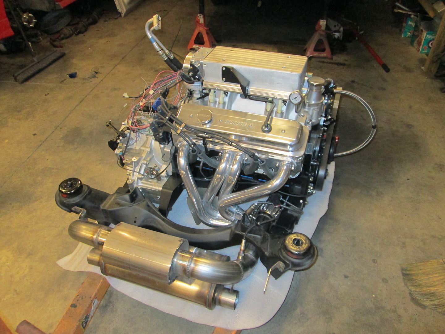
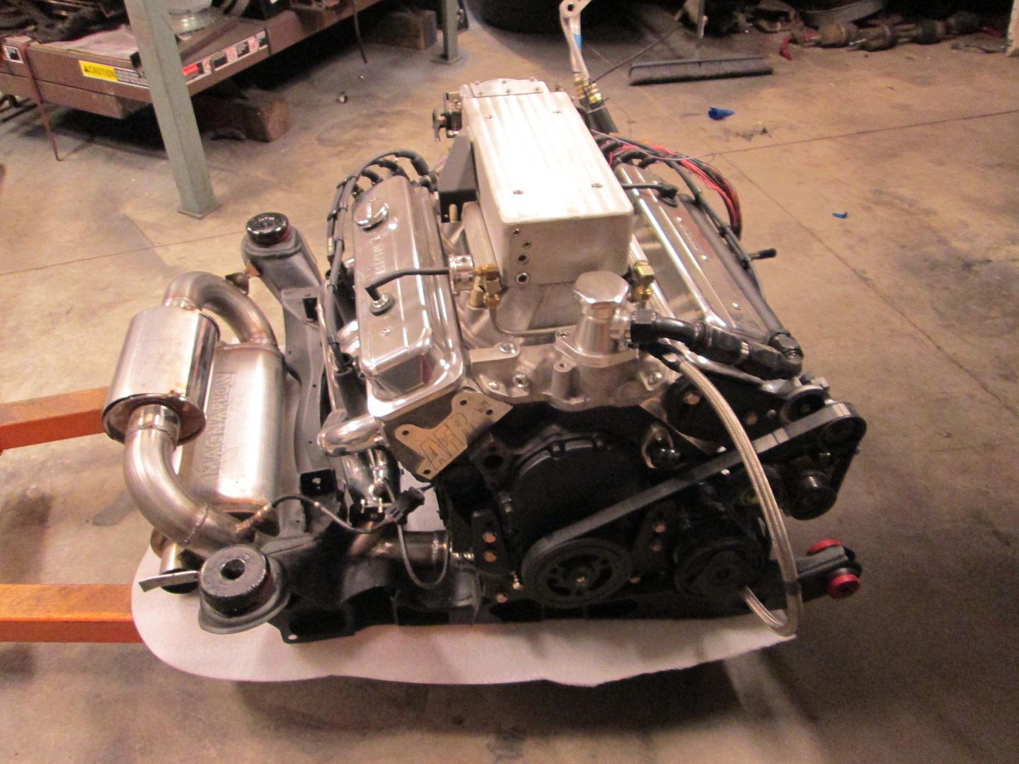
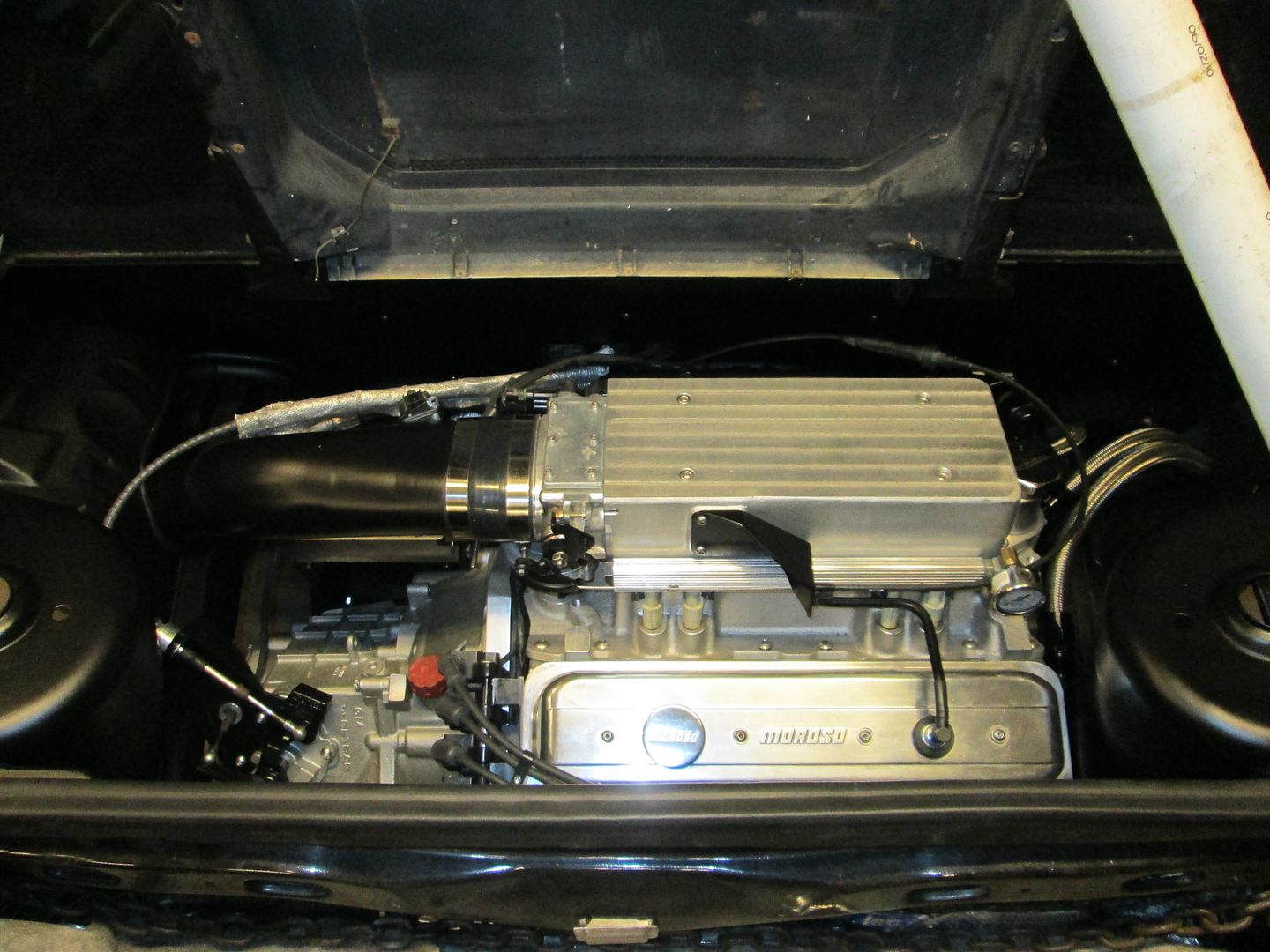
Here are some painted assembly pictures + some progress building the harness:
The visible side:
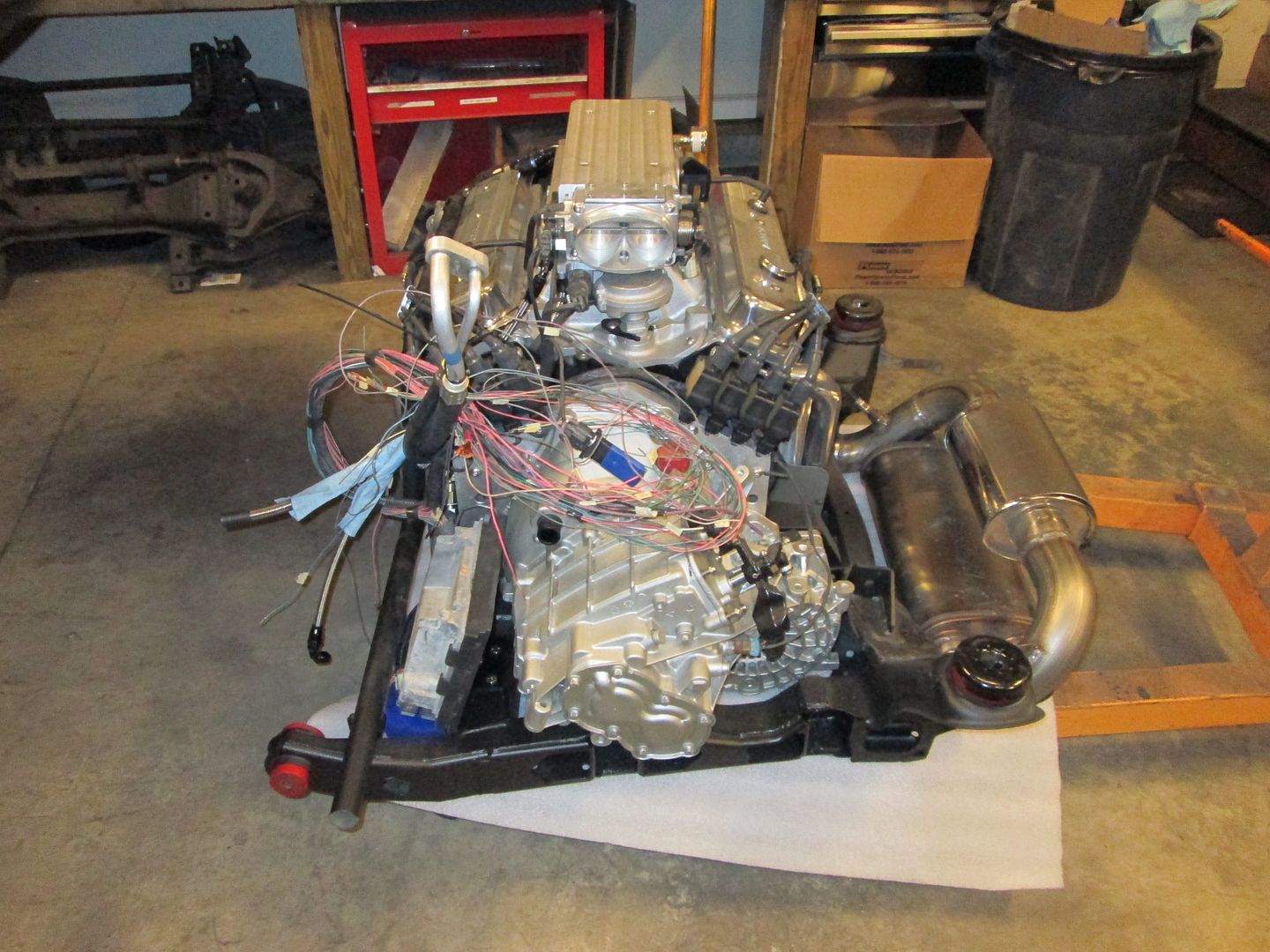
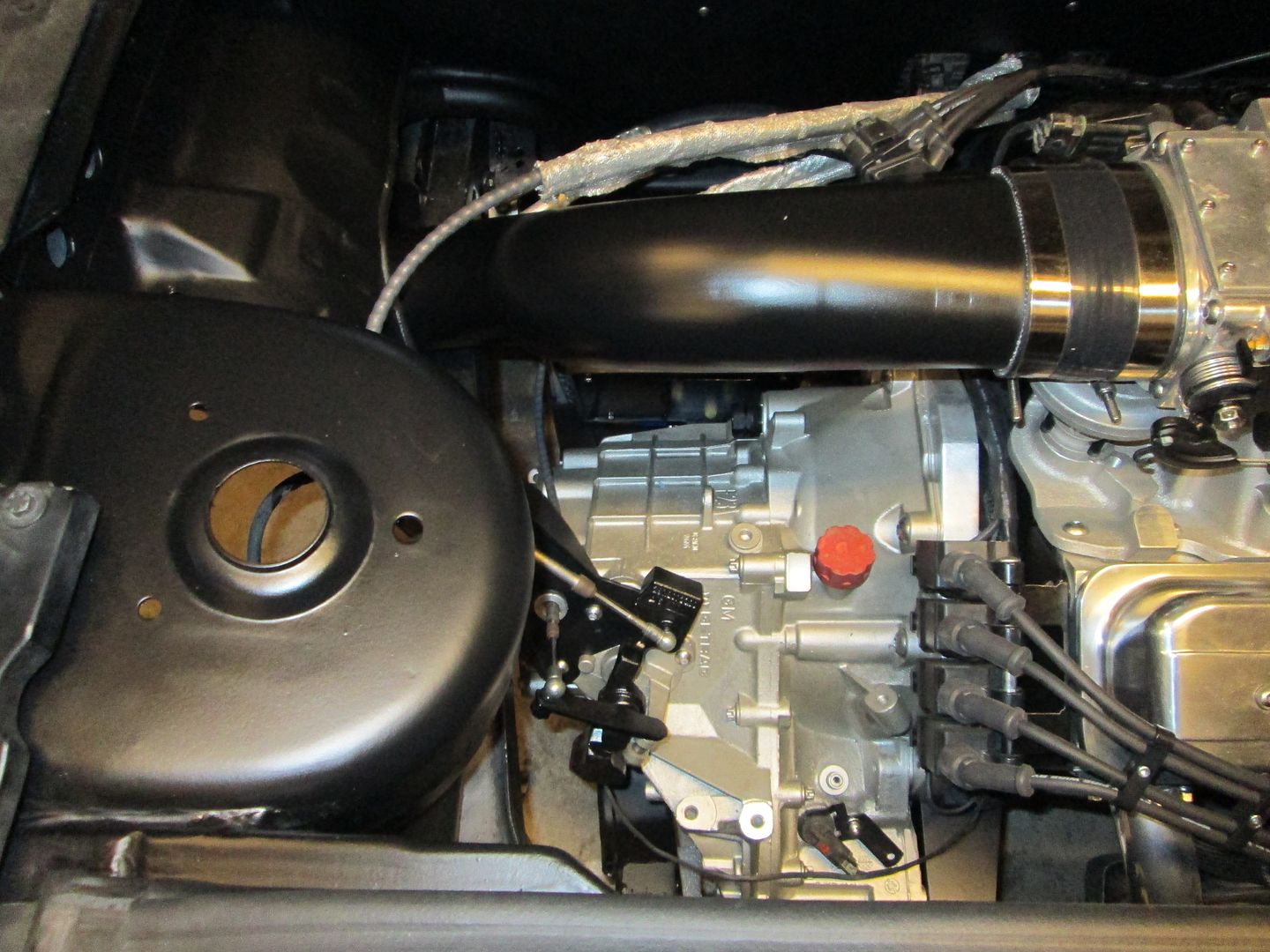
The ugly/hidden side:
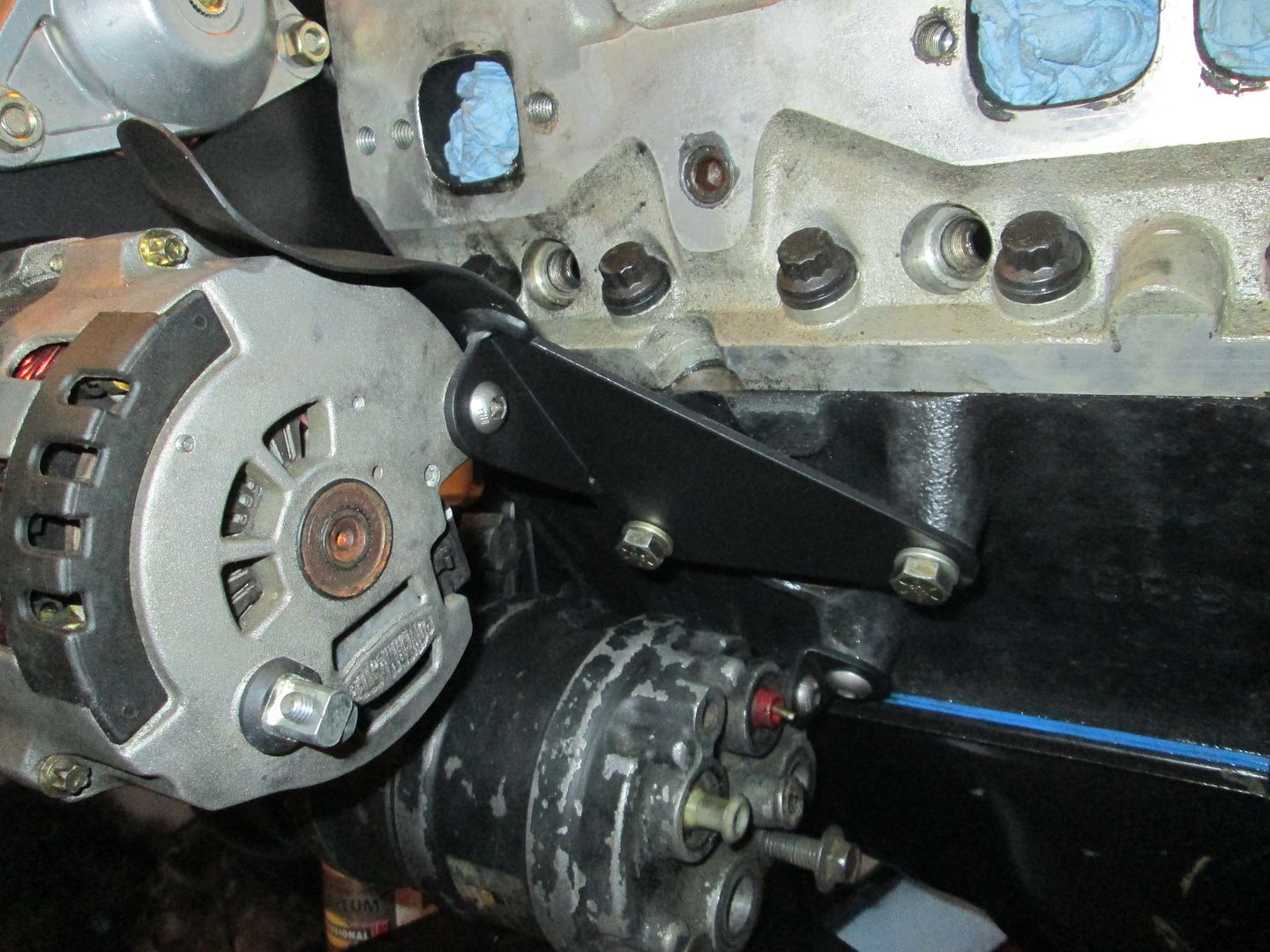
Accessory Drive:
Rear supports for A/C and Alternator:
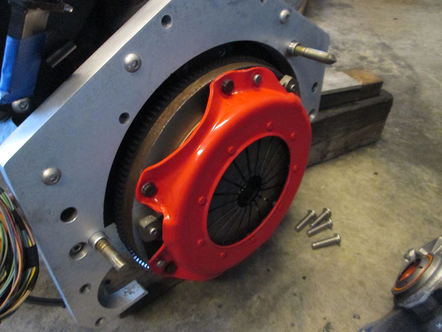
Adapter plate & Clutch:
Transmission shifter brackets:
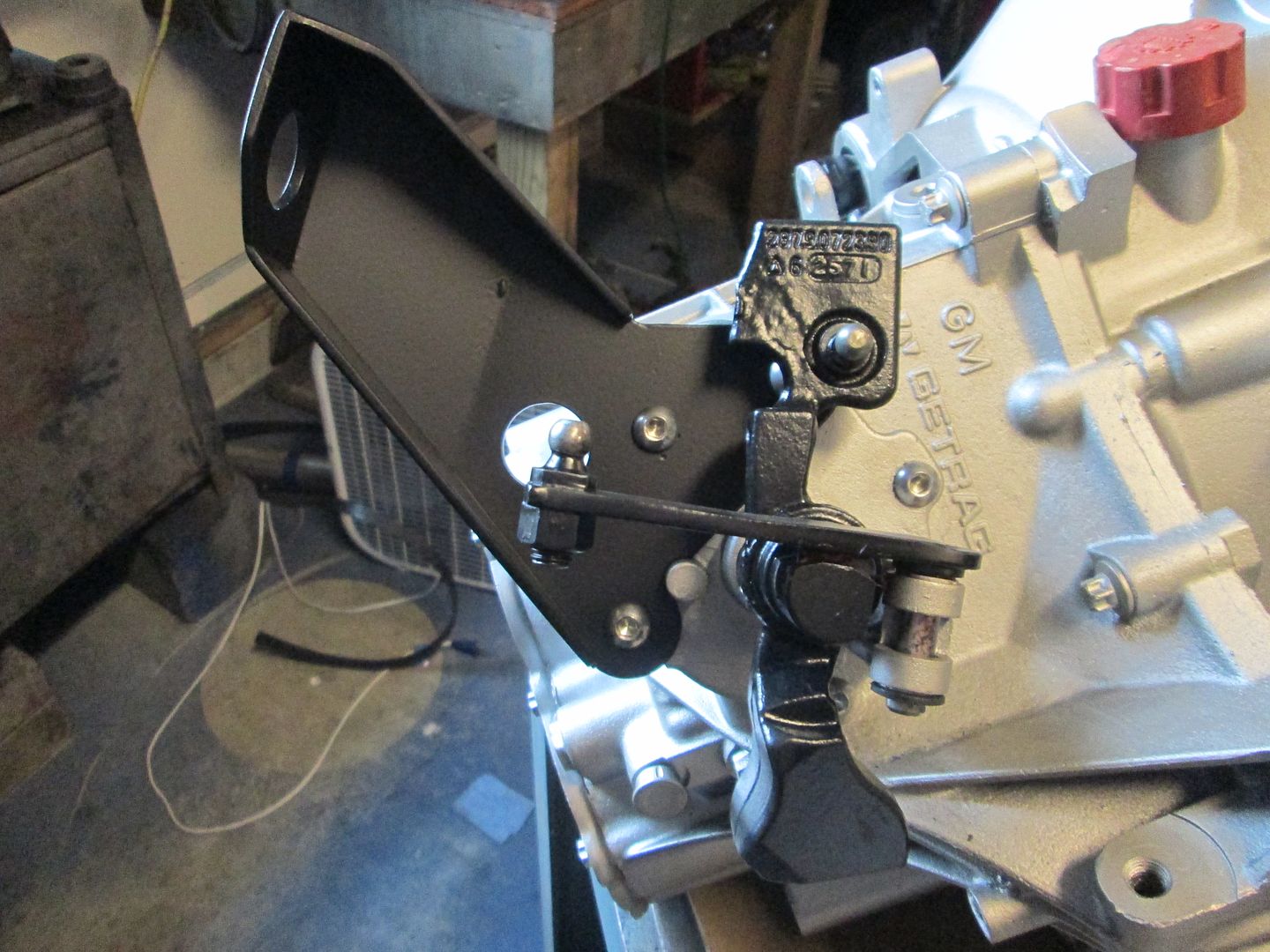
Front transmission mount:
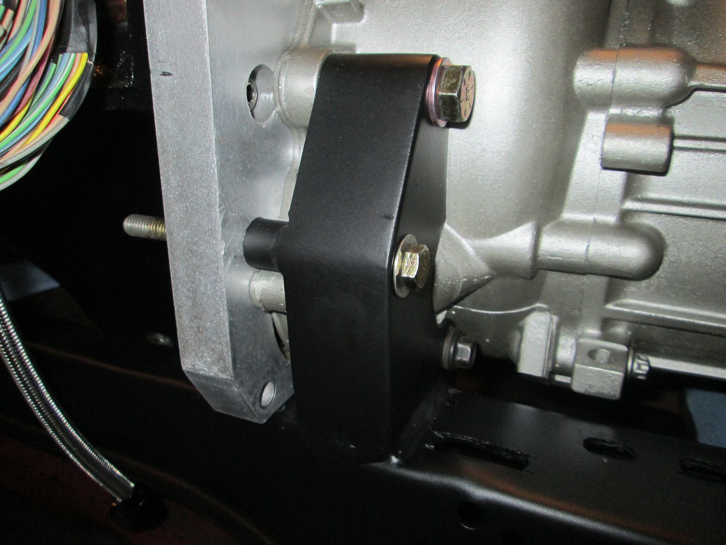
Rear transmission mount:
Starting the wiring:

The visible side:
The ugly/hidden side:
Accessory Drive:
Rear supports for A/C and Alternator:
Adapter plate & Clutch:
Transmission shifter brackets:
Front transmission mount:
Rear transmission mount:
Starting the wiring: