
1967 Cougar build (over 500 pictures and videos)
 11-07-2018, 08:58 PM
#921
TECH Senior Member
Thread Starter
iTrader: (7)

http://www.dcemotorsport.com/Home/EPAS
Their Microsteer system looks really good for street applications and has a very capable ECU and well priced ($900), considering what you get.
Andrew
 11-07-2018, 09:06 PM
#922
TECH Senior Member

Wow! Just checked out the site you linked to. Nice stuff! I wouldn't doubt others like Flaming River or Ididit will do similar stuff sooner than later.
 11-08-2018, 08:17 AM
#923
TECH Fanatic

i like this, isaw the pump you linked to was good for 80ftlbs......dont know if that would enough to turn the wheels on the caddy?? lol
i am interested in this as well as manual brakes,and get rid of all the hydroboost stuff. gotta figure out how it would play with 5k lbs.....
ill be checking back on this, very cool,
i am interested in this as well as manual brakes,and get rid of all the hydroboost stuff. gotta figure out how it would play with 5k lbs.....
ill be checking back on this, very cool,
 11-08-2018, 09:58 AM
#925
TECH Senior Member
Thread Starter
iTrader: (7)
i like this, isaw the pump you linked to was good for 80ftlbs......dont know if that would enough to turn the wheels on the caddy?? lol
i am interested in this as well as manual brakes,and get rid of all the hydroboost stuff. gotta figure out how it would play with 5k lbs.....
ill be checking back on this, very cool,
i am interested in this as well as manual brakes,and get rid of all the hydroboost stuff. gotta figure out how it would play with 5k lbs.....
ill be checking back on this, very cool,
Andrew
11-08-2018, 12:02 PM
#926
Curious how this ends up working out. Many, many newer cars have had electric "boost" or racks for quite some time now. And many of those systems get routinely criticized for being vague, over boosted and having essentially no feel/feedback at all. Now, if you're converting something that had those same issues before (almost all American muscle, for example...) then nothing lost and a better steering assist mousetrap. But if you have rack and pinion with decent feel/feedback -- be careful. Easy to lose that unless you can crack the code on how to alter the boost programming to mimic the feel/feedback you had before. It is doable - in the last few years, many OEM have really good electric systems -- the system in my wife's Subaru and in my Mazda3 feel about the same to me as good hydraulic rack. But the programming is the key.
11-08-2018, 12:39 PM
#927
TECH Senior Member
My '13 F150 has EPS, and I love it! Granted, one doesn't look for the same feedback in a pickup as a Miata, but I have a feeling the last few years brought about a few improvements, as with anything else. Remember where hydraulic PS was 30-40 years ago? EPS is improving even faster.
11-08-2018, 08:20 PM
#929
TECH Senior Member
Thread Starter
iTrader: (7)
I also plan to make this system be speed sensitive. More on this when I get to the wiring and testing.
Andrew
11-08-2018, 08:26 PM
#930
TECH Senior Member
Thread Starter
iTrader: (7)
Made some really good progress today. The UPS truck showed up right on time, but then my buddy Jack asked me if I wanted to get an early lunch. Needless to say, I didn't get started until about 1:00PM. I keep forgetting that it will get dark around 5:00PM!
I mentioned before that the 1.5" bore collars have the same OD as the steering tube. So I attached a couple of them to the Prius motor assembly and mocked things up in the car. The motor ends up being clocked at about the 2:30 position. I wish I could move it up some more, but the wiper motor is right there. I thought about using some sort of smaller motor for the wipers, but given the time frame of this project, I will have to leave that for another day.
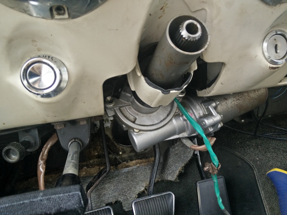
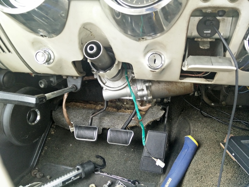
It looks like it will be in the way when viewed from a low angle, but in reality, when sitting behind the wheel, the motor is barely noticeable. It also doesn't get in the way of the feet. Oh, BTW, the new bearing pedals feel amazing!!! Super smooth and just solid.
Also, the steering ECU is going to live up against the firewall, over in the corner where the dimmer switch lives. You can sort of see the spot in the picture above.

With the Prius motor mounted, I was able to take some measurements. I had to take into account the collar that I machined yesterday, etc...etc...I expanded the slot a little so the set screw would slide in.

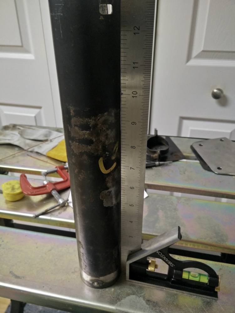
Here is the cut upper tube.

I needed it to be 14.5" total, with the turn signal portion of the column attached.

Then came the scary part. I knew that when I cut the column tube, it wasn't going to be perfectly square. I also knew that the collar "machine" job wasn't perfect either. With that said, I had to make sure that the collar was square to the tube. I actually messed up the first time. This was my second attempt and I think I got it good enough for what this is.

Rotated 90 degrees.
With the tube tacked to the collar, it was time to mock it up in the car, one more time. The length was perfect and the stock upper column support fits perfectly with the anti-rotation tab fitting in its slot.
Then came the paralysis by analysis. As I mentioned earlier, my plan was to make a shaft on the output side of the motor and pass it through a bearing that was to be mounted to a plate (I made this plate yesterday!) in the location where the stock lower column support attaches. As I was looking at the mounted motor and feeling how much it rocked up and down, I just wasn't comfortable with my original plan. I know people have done exactly that and the steering shaft will of course help to stabilize the upper column, but I just didn't feel comfortable with it.
The output shaft has a lot of torque on it already and then stressing it in other directions to stabilize the whole column seems like a big ask for a 3/4" shaft. I decided that I was going to build a lower tube. Having a lower tube that attaches to the motor will put the loads of holding the column rigid on the tubes, and allowing the shaft to take only the forces of steering the car.
I was at Tractor Supply yesterday, buying some hardware. However, I looked all around the store just to see what they have. I remembered seeing some bearing flanges so I went back today with some measurements in hand. I ended up buying these (came in a pack of two). The size was right and they are stamped out of 14 gauge material. Plenty sturdy for this project.

What I needed to do next was to get them concentric with the output shaft. I ended up using the bearing from the firewall mount and wrapping it in making tape to make up for the diameter difference. The ID of the bearing fit the output shaft of the steering motor perfectly and I kept it in place with a couple of set screws that are on the bearing collar.

If I was This Old Tony (from YouTube), I would have machined a perfect alignment tool for the job, but I am working in my kitchen FFS...
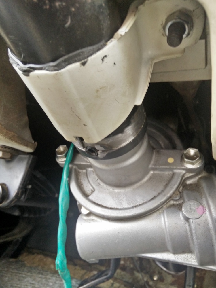
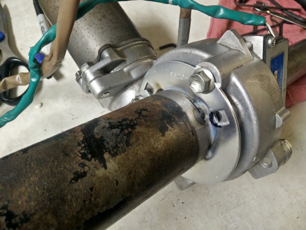
I then took the lower bearing from my old column. This part is obviously not stock but came from TCP as part of their rack and pinion kit. At this point, the lower tube is not cut to length.

You can also see that I have the steering shaft installed and it is attached to the coupler that matches the splines of the Toyota motor and transitions to 3/4" smooth bore. I then pushed the steering shaft and the tube up against the flange. The flange has a smooth tapper and the tube has the factory square cut. This forced the tube to be concentric and square.


Then I fired up the welder and made some tacks around the circumference of the tube. Yes, I forgot to grind the zinc platting off the flange. Yes, there were fumes...pray for me....please...

After tacking the tube to the flange, I mode holes in the flange for attaching hardware and installed the whole thing, passing the lower tube through the lower column support and into the engine bay. I don't have pictures of this because it was almost dark out. With the column installed, I mocked up the intermediate shaft from the rack, and laid out the right length for the lower column tube. Here is the final lower tube, cut to length.

There will be a total of 3 bolts that hold the lower tube to the motor assembly. That is all the holes that are driller and tapped in the motor casting. There is another hole that is marked, but not fully drilled or tapped. I thought about drilling and tapping this location, but I figured the 3 bolts are plenty, even though they are not symmetrically located.
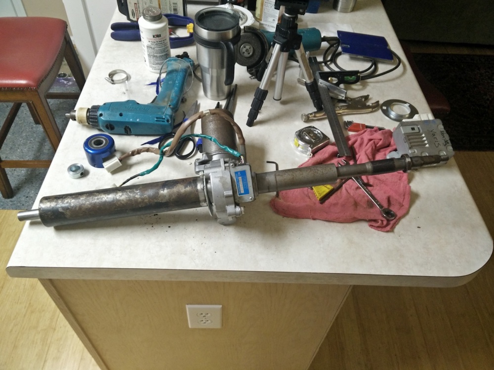
And here we have it; the whole column, sans the upper portion. The upper shaft is the stock Toyota shaft. This needs to be cut and mated to the Cougar upper shaft.
Tomorrows task are:
1. Finalize the lower shaft.
2. Complete the upper shaft
3. Quick strip and paint the upper column in parchment color and lower column in black.
4. Install column for good.
5. Wiring and testing!
If you like what you're reading, please subscribe to my YouTube channel. I will have videos of all this uploaded next week.
Andrew
I mentioned before that the 1.5" bore collars have the same OD as the steering tube. So I attached a couple of them to the Prius motor assembly and mocked things up in the car. The motor ends up being clocked at about the 2:30 position. I wish I could move it up some more, but the wiper motor is right there. I thought about using some sort of smaller motor for the wipers, but given the time frame of this project, I will have to leave that for another day.
It looks like it will be in the way when viewed from a low angle, but in reality, when sitting behind the wheel, the motor is barely noticeable. It also doesn't get in the way of the feet. Oh, BTW, the new bearing pedals feel amazing!!! Super smooth and just solid.
Also, the steering ECU is going to live up against the firewall, over in the corner where the dimmer switch lives. You can sort of see the spot in the picture above.
With the Prius motor mounted, I was able to take some measurements. I had to take into account the collar that I machined yesterday, etc...etc...I expanded the slot a little so the set screw would slide in.
Here is the cut upper tube.
I needed it to be 14.5" total, with the turn signal portion of the column attached.
Then came the scary part. I knew that when I cut the column tube, it wasn't going to be perfectly square. I also knew that the collar "machine" job wasn't perfect either. With that said, I had to make sure that the collar was square to the tube. I actually messed up the first time. This was my second attempt and I think I got it good enough for what this is.
Rotated 90 degrees.
With the tube tacked to the collar, it was time to mock it up in the car, one more time. The length was perfect and the stock upper column support fits perfectly with the anti-rotation tab fitting in its slot.
Then came the paralysis by analysis. As I mentioned earlier, my plan was to make a shaft on the output side of the motor and pass it through a bearing that was to be mounted to a plate (I made this plate yesterday!) in the location where the stock lower column support attaches. As I was looking at the mounted motor and feeling how much it rocked up and down, I just wasn't comfortable with my original plan. I know people have done exactly that and the steering shaft will of course help to stabilize the upper column, but I just didn't feel comfortable with it.
The output shaft has a lot of torque on it already and then stressing it in other directions to stabilize the whole column seems like a big ask for a 3/4" shaft. I decided that I was going to build a lower tube. Having a lower tube that attaches to the motor will put the loads of holding the column rigid on the tubes, and allowing the shaft to take only the forces of steering the car.
I was at Tractor Supply yesterday, buying some hardware. However, I looked all around the store just to see what they have. I remembered seeing some bearing flanges so I went back today with some measurements in hand. I ended up buying these (came in a pack of two). The size was right and they are stamped out of 14 gauge material. Plenty sturdy for this project.
What I needed to do next was to get them concentric with the output shaft. I ended up using the bearing from the firewall mount and wrapping it in making tape to make up for the diameter difference. The ID of the bearing fit the output shaft of the steering motor perfectly and I kept it in place with a couple of set screws that are on the bearing collar.
If I was This Old Tony (from YouTube), I would have machined a perfect alignment tool for the job, but I am working in my kitchen FFS...
I then took the lower bearing from my old column. This part is obviously not stock but came from TCP as part of their rack and pinion kit. At this point, the lower tube is not cut to length.
You can also see that I have the steering shaft installed and it is attached to the coupler that matches the splines of the Toyota motor and transitions to 3/4" smooth bore. I then pushed the steering shaft and the tube up against the flange. The flange has a smooth tapper and the tube has the factory square cut. This forced the tube to be concentric and square.
Then I fired up the welder and made some tacks around the circumference of the tube. Yes, I forgot to grind the zinc platting off the flange. Yes, there were fumes...pray for me....please...
After tacking the tube to the flange, I mode holes in the flange for attaching hardware and installed the whole thing, passing the lower tube through the lower column support and into the engine bay. I don't have pictures of this because it was almost dark out. With the column installed, I mocked up the intermediate shaft from the rack, and laid out the right length for the lower column tube. Here is the final lower tube, cut to length.
There will be a total of 3 bolts that hold the lower tube to the motor assembly. That is all the holes that are driller and tapped in the motor casting. There is another hole that is marked, but not fully drilled or tapped. I thought about drilling and tapping this location, but I figured the 3 bolts are plenty, even though they are not symmetrically located.
And here we have it; the whole column, sans the upper portion. The upper shaft is the stock Toyota shaft. This needs to be cut and mated to the Cougar upper shaft.
Tomorrows task are:
1. Finalize the lower shaft.
2. Complete the upper shaft
3. Quick strip and paint the upper column in parchment color and lower column in black.
4. Install column for good.
5. Wiring and testing!
If you like what you're reading, please subscribe to my YouTube channel. I will have videos of all this uploaded next week.
Andrew
11-08-2018, 09:04 PM
#933
Had to go back and remind myself - forgotten you'd put the TCP rack in it Andrew. Thought you were still dealing with recirculating ball - my bad. So, I didn't think your application was subject to this line --- "But if you have rack and pinion with decent feel/feedback -- be careful." While speed sensitivity may help, I think it will be interesting to see how the unit impacts feel and feedback. My problem is that I've owned a few cars over the decades with the best steering feel/feedback/responsiveness around. I've become a steering feel snob. As you pointed out, all sorts of things go into making any steering system work well AND provide good feel and feedback. Geometry, chassis stiffness, tires/wheels/alignment designed with the boost system in mind -- the list goes on. OEM's have spent tons of R&D time/$ tuning their systems to work - and it's really been in just the last 5 years that they've come to rival the best old manual and hyd-boost systems. I think it will be difficult to emulate that in a junkyard/aftermarket application.
11-08-2018, 09:53 PM
#934
TECH Senior Member
Thread Starter
iTrader: (7)
Had to go back and remind myself - forgotten you'd put the TCP rack in it Andrew. Thought you were still dealing with recirculating ball - my bad. So, I didn't think your application was subject to this line --- "But if you have rack and pinion with decent feel/feedback -- be careful." While speed sensitivity may help, I think it will be interesting to see how the unit impacts feel and feedback. My problem is that I've owned a few cars over the decades with the best steering feel/feedback/responsiveness around. I've become a steering feel snob. As you pointed out, all sorts of things go into making any steering system work well AND provide good feel and feedback. Geometry, chassis stiffness, tires/wheels/alignment designed with the boost system in mind -- the list goes on. OEM's have spent tons of R&D time/$ tuning their systems to work - and it's really been in just the last 5 years that they've come to rival the best old manual and hyd-boost systems. I think it will be difficult to emulate that in a junkyard/aftermarket application.
There are plenty of EPS steering systems being used in all manner of motorsports, as shown in the link for DCE Motorpsort systems. They cater to every level of professions and amateur motorsport devisions, so it can't all be bad. Obviously, DCE has their own ECUs, which is what adds value to their systems. My only system requirement is reduced steering effort. This goal should be easily accomplished with the hardware and electronics that I am using. The speed sensitive element will be the cherry on top.
Andrew
11-08-2018, 11:12 PM
#936
TECH Fanatic
11-09-2018, 10:09 PM
#937
TECH Senior Member
Thread Starter
iTrader: (7)
Today was a miserable looking day. It was raining all morning and I wasn't able to get as much done as I wanted, but I made solid progress.
The gentleman that first documented the Toyota Prius installation had a couple of suggestions as to how to make the upper shaft. Here is what he did on his Falcon:


I didn't see anything wrong with how he did it, but there is one problem, I don't have a lathe. Even if I did, instead of turning down the Falcon shaft, I would have bored out the Toyota stub to .750" to accept the Falcon shaft. Anyway, doesn't matter, no lathe.
Keep in mind, the Toyota stub has internal splines on the left side of the shaft. I made my first cut where he suggested, and as he noted a stock .750" shaft doesn't fit. However, notice that the Toyota stub has a little bulge, so if a cut can be made a little further to the right of where he made his cut, the ID gets bigger. So I took my wizwheelofdeath and cut off about 1/8" off the Toyota stub.

I was getting close now. Making that second cut got me really close to .750", so from here on out, I snuck up on it with a file. I wanted the Cougar shaft to fit snugly into the Toyota stub.

I cut the Cougar shaft a little long, so I can trim it exactly to the right length later. Here you can see the Cougar shaft fitting snugly into the Toyota stub.

You can also see by the silver mark, how far the Cougar shaft slides into the Toyota stub. This is important, because the Cougar shaft bottoms out on a taper that is inside the Toyota stub.
By having a tight fit at the opening of the stub and then having the shaft bottom out into a snug taper, assures that the two shafts are concentric to each other. This is obviously important, because we want as straight of a shaft as possible.
The final length of the Toyota stub ended up being right at 5.100"

Now it was time to cut the Cougar shaft to length. Again, a lathe would be the perfect way to do it, but no lathe. I had purchased a few .750" ID collar at Tractor Supply (officially my new favorite store) and I used one of them as a guide for my whizwheelofdeath.
This worked very well and gave a pretty square cut. The other thing that I wanted to do was stake the two shafts together. My welding is OK, but this is pretty critical hardware. So I drilled a 1/4" hole through both the Toyota stub and the Cougar shaft.

I then took a 1/4" grade 8 bolt and provided a mechanical pin that holds both shafts together. Then I cut the bolt and welded it in.

Then I welded the Toyota stub to the Cougar shaft.

The lower shaft is pretty straight forward. I used a Burgeson adapter with the Toyota spline on one side and a .750" smooth bore on the other side. Here I did exactly the same thing. Drilled a hole through the adapter and the shaft, 1/4" grade 8 bolt, welded bolt, then welded shaft to adapter.

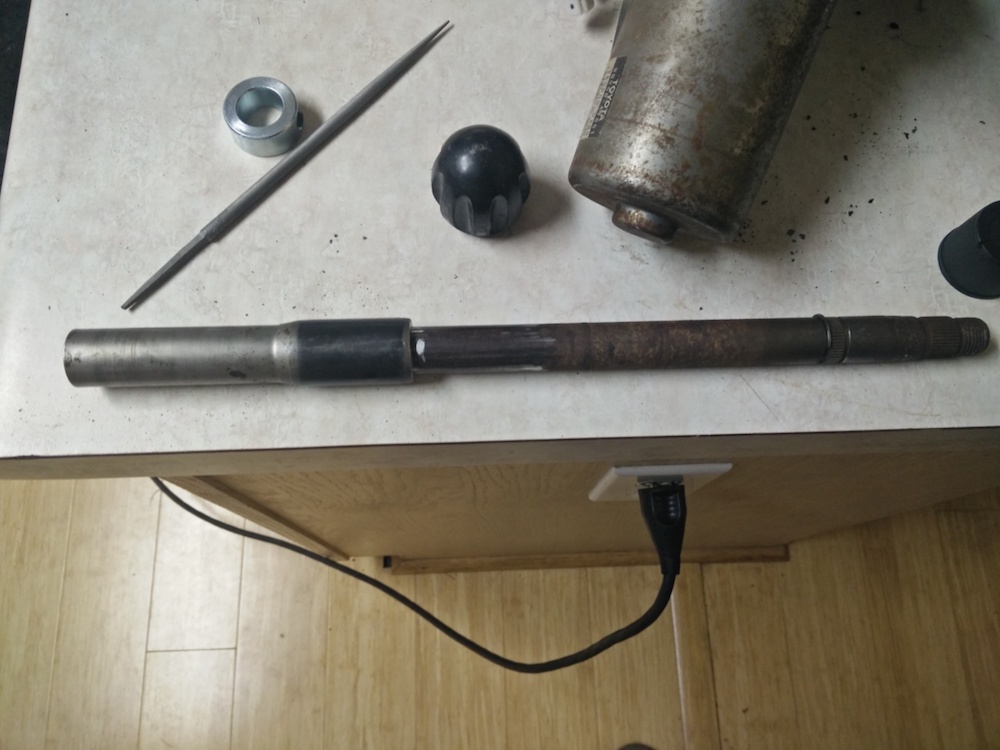
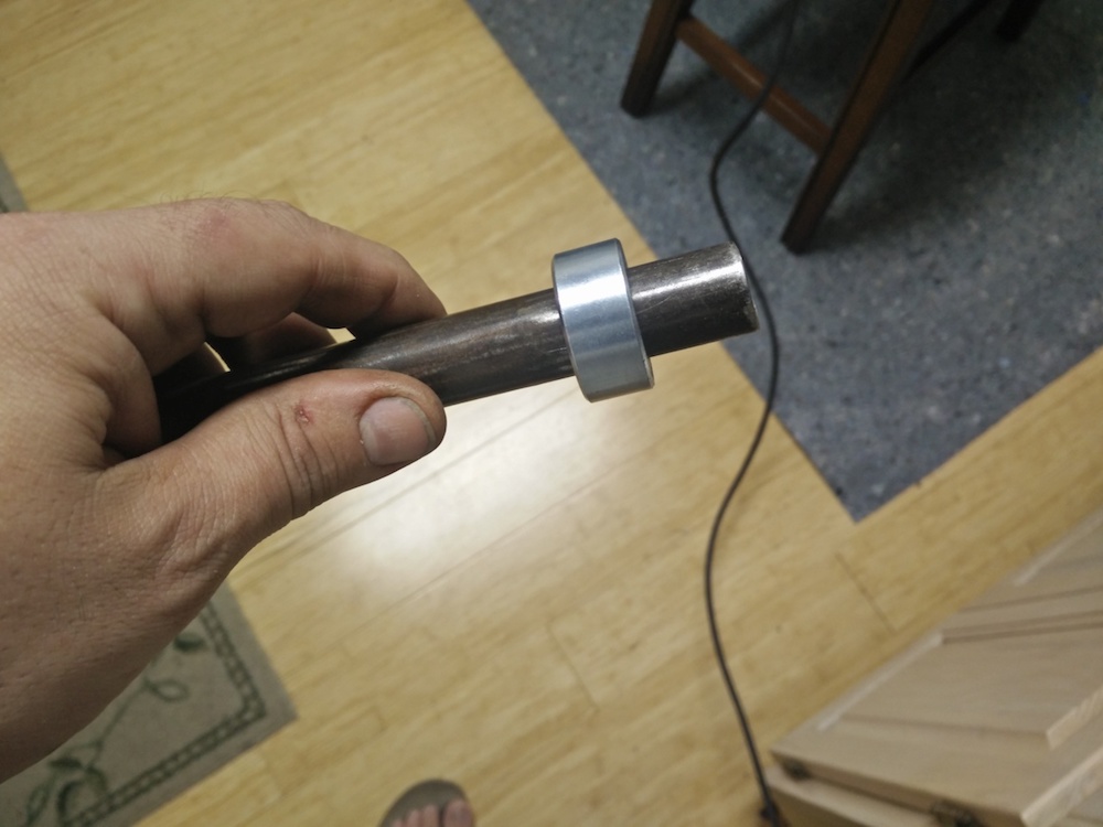
Here is the final upper shaft. It ended up being 13 5/16" overall length. Keep in mind there is some wiggle room here because the left side of the shaft is splined. I made it as long as possible to engage those splined fully. The collar is there to keep the steering shaft from pulling out the top and it bottoms against the upper portion of the column. I really don't see this being an issue, because the splines on the Toyota stub fit really, really tightly on the input shaft of the motor, but I wanted a positive stop there anyway.
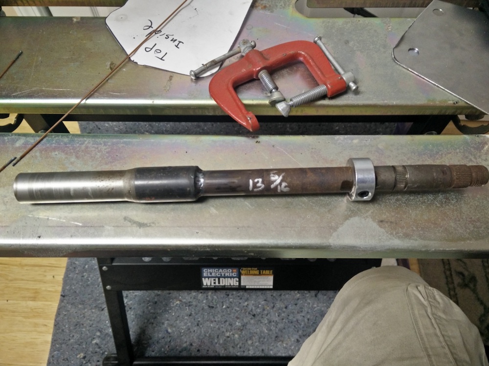
With the shaft installed and the upper tube attached you can see that the shaft length is perfect. You can see the groove for a circlip just above the stock upper bearing.

This is the lower shaft installed on the output side of the Toyota motor.

I ground flats on the end of the lower shaft (this was harder than it seemed) to mate with the u-joints for the intermediate shaft.

And here it is, fully assembled and ready for a coat of paint tomorrow.
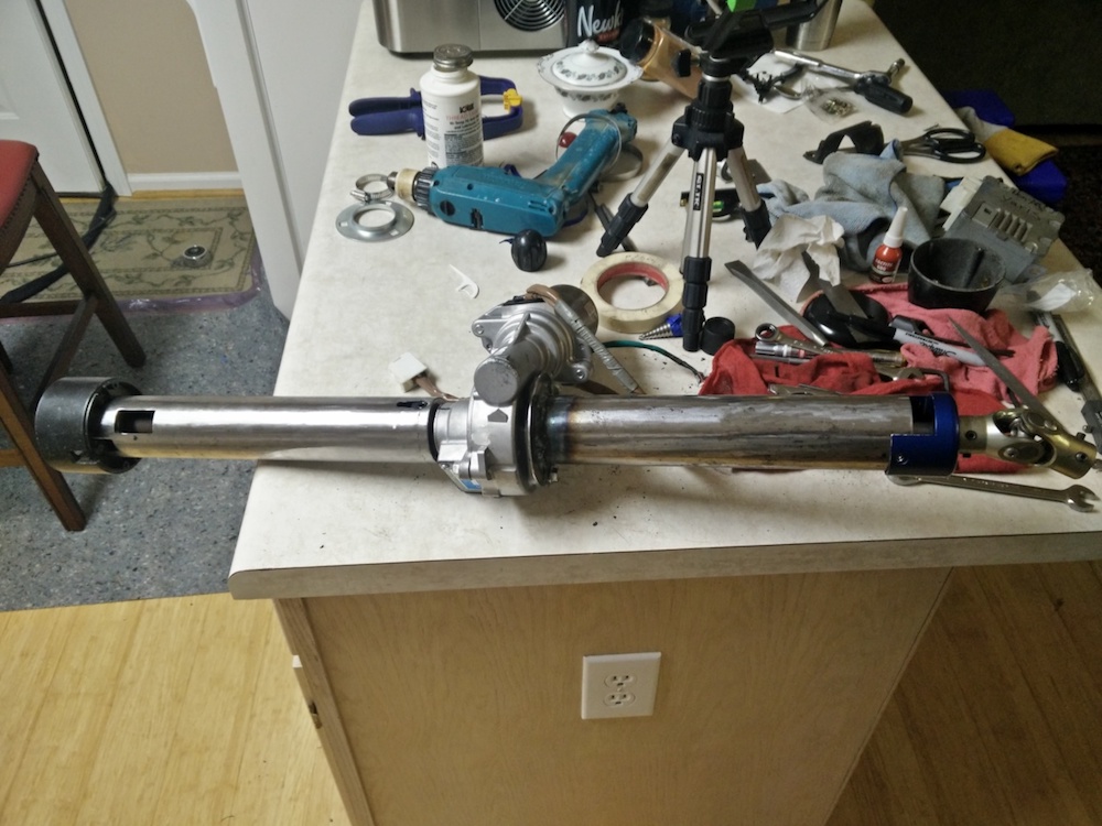
The weather is supposed to be sunny tomorrow, so I am going to throw this thing in the car ASAP, get it temporarily wired up, and see if it actually works.
Andrew
The gentleman that first documented the Toyota Prius installation had a couple of suggestions as to how to make the upper shaft. Here is what he did on his Falcon:
I didn't see anything wrong with how he did it, but there is one problem, I don't have a lathe. Even if I did, instead of turning down the Falcon shaft, I would have bored out the Toyota stub to .750" to accept the Falcon shaft. Anyway, doesn't matter, no lathe.
Keep in mind, the Toyota stub has internal splines on the left side of the shaft. I made my first cut where he suggested, and as he noted a stock .750" shaft doesn't fit. However, notice that the Toyota stub has a little bulge, so if a cut can be made a little further to the right of where he made his cut, the ID gets bigger. So I took my wizwheelofdeath and cut off about 1/8" off the Toyota stub.
I was getting close now. Making that second cut got me really close to .750", so from here on out, I snuck up on it with a file. I wanted the Cougar shaft to fit snugly into the Toyota stub.
I cut the Cougar shaft a little long, so I can trim it exactly to the right length later. Here you can see the Cougar shaft fitting snugly into the Toyota stub.
You can also see by the silver mark, how far the Cougar shaft slides into the Toyota stub. This is important, because the Cougar shaft bottoms out on a taper that is inside the Toyota stub.
By having a tight fit at the opening of the stub and then having the shaft bottom out into a snug taper, assures that the two shafts are concentric to each other. This is obviously important, because we want as straight of a shaft as possible.
The final length of the Toyota stub ended up being right at 5.100"
Now it was time to cut the Cougar shaft to length. Again, a lathe would be the perfect way to do it, but no lathe. I had purchased a few .750" ID collar at Tractor Supply (officially my new favorite store) and I used one of them as a guide for my whizwheelofdeath.
This worked very well and gave a pretty square cut. The other thing that I wanted to do was stake the two shafts together. My welding is OK, but this is pretty critical hardware. So I drilled a 1/4" hole through both the Toyota stub and the Cougar shaft.
I then took a 1/4" grade 8 bolt and provided a mechanical pin that holds both shafts together. Then I cut the bolt and welded it in.
Then I welded the Toyota stub to the Cougar shaft.
The lower shaft is pretty straight forward. I used a Burgeson adapter with the Toyota spline on one side and a .750" smooth bore on the other side. Here I did exactly the same thing. Drilled a hole through the adapter and the shaft, 1/4" grade 8 bolt, welded bolt, then welded shaft to adapter.
Here is the final upper shaft. It ended up being 13 5/16" overall length. Keep in mind there is some wiggle room here because the left side of the shaft is splined. I made it as long as possible to engage those splined fully. The collar is there to keep the steering shaft from pulling out the top and it bottoms against the upper portion of the column. I really don't see this being an issue, because the splines on the Toyota stub fit really, really tightly on the input shaft of the motor, but I wanted a positive stop there anyway.
With the shaft installed and the upper tube attached you can see that the shaft length is perfect. You can see the groove for a circlip just above the stock upper bearing.
This is the lower shaft installed on the output side of the Toyota motor.
I ground flats on the end of the lower shaft (this was harder than it seemed) to mate with the u-joints for the intermediate shaft.
And here it is, fully assembled and ready for a coat of paint tomorrow.
The weather is supposed to be sunny tomorrow, so I am going to throw this thing in the car ASAP, get it temporarily wired up, and see if it actually works.
Andrew