

LS3 – 525HP / Legend LGT-700 Conversion in a 66 Pontiac GTO Convertible
 11-23-2014, 09:39 PM
#21


Ridetech all the way!
Long weekend in the garage with some decent results.
I got the Radaflex 1/0 donkey dick starter cable from Cable Yard and I got that ran that on the passenger side from the trunk to the starter. Waiting on the hydraulic crimper to arrive and I can go to town terminating the cable. I was going to mount the battery on the passenger side of the trunk, but I am seriously considering running a spare tire and the factory spare hook is still in the trunk which makes the location ideal for the spare. With the LS, I plan on driving this thing a bunch more and I really want a spare for the piece of mind. Just need to find a 04-06 GTO spare - close fit...enough to get me where I need to go.
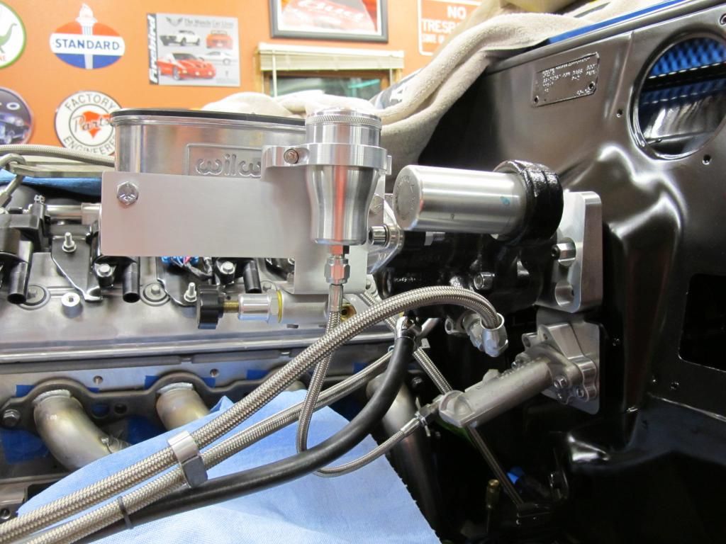
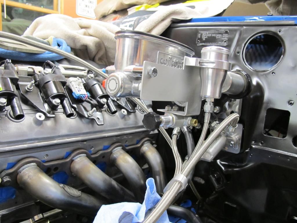
Next on task was to figure out a bracket to mount my proportioning valve and the clutch master reservoir. I opted for a Ring Brothers billet deal which is killer and only a few bucks more than a plain plastic deal. I knew I wanted everything to be located on the brake master cylinder to keep the firewall clean. Starting with some poster board templates, I played around with some patterns. Using some 0.090" aluminum I had sitting around, this is what I came up with. Pretty clean installation
I made up some wire templates for brake lines and I like stainless so I will be shipping these templates off to Right Stuff to have them bend them up for me.
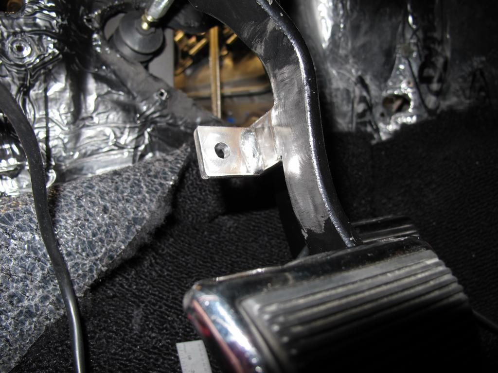
Next on tap was to tackle the clutch pedal mods. I have played around with this before and knew that I could not do a simple heim joint at the clutch pedal because the pedal and the clutch master are not in perfect alignment. Side load is death to a master and so I needed another solution. SOOOOOOO...What to do?
Starting with a piece of 1/4" X 1" flat stock, I welded a long rod nut to the flat stock. I then drilled a hole in the end of the stock for a pivot point.
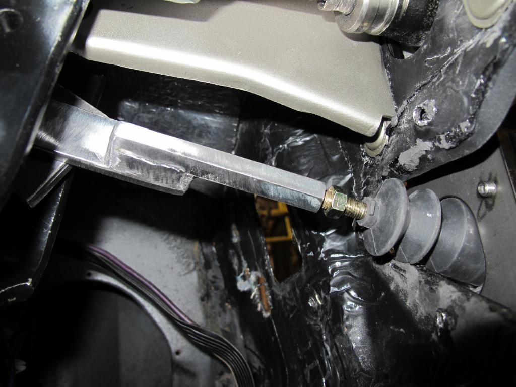
Because of hydraulic setup does not have as much of an angle as the mechanical setup, I had to make a bracket that relocates the pivot point lower on the clutch pedal. As mentioned earlier, the clutch pedal is not in alignment with the master rod. With the new push rod bracket and the clutch pedal adapter piece, I end up needing only a 0.030" thick washer to get the push rod dead nuts in alignment with the clutch master. For the vertical angle, i used my Wixley digital angle finder to match angles between the master body and the input shaft. The angle finder is very compact and I was able to measure the angle off of the master body and the input rod and set the two equal to each other. I plan on adding a bronze bushing for the pivot pin.
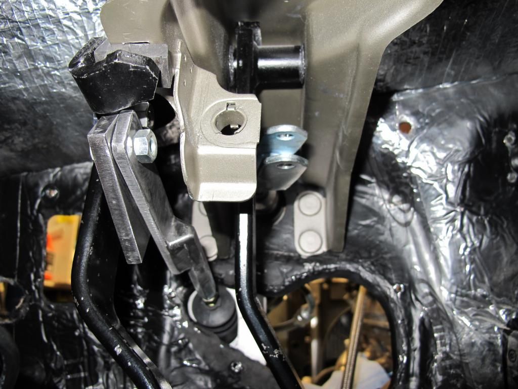
I also made a clutch pedal stop and welded that to the clutch pedal. Just need to find a bumper and a 5/16" rod.
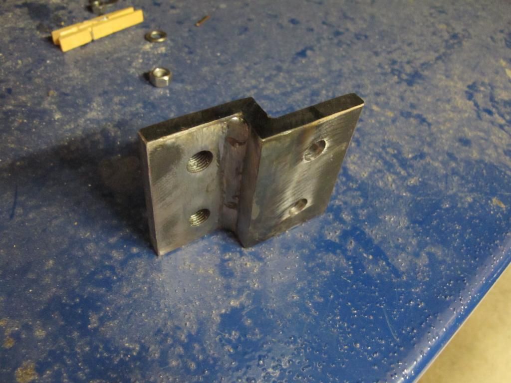
Next up was to make an adapter plate for the crossmember to the transmission mount. Using 3/8" plate, I welded up a couple of pieces of steel and finished them off with a grinder.
Last weekend: I got my order of Aeroquip parts from the Hose Warehouse a week or so ago and plumbed up the Corvette style regulator. Just wished that the input and the return were separated a bit more.
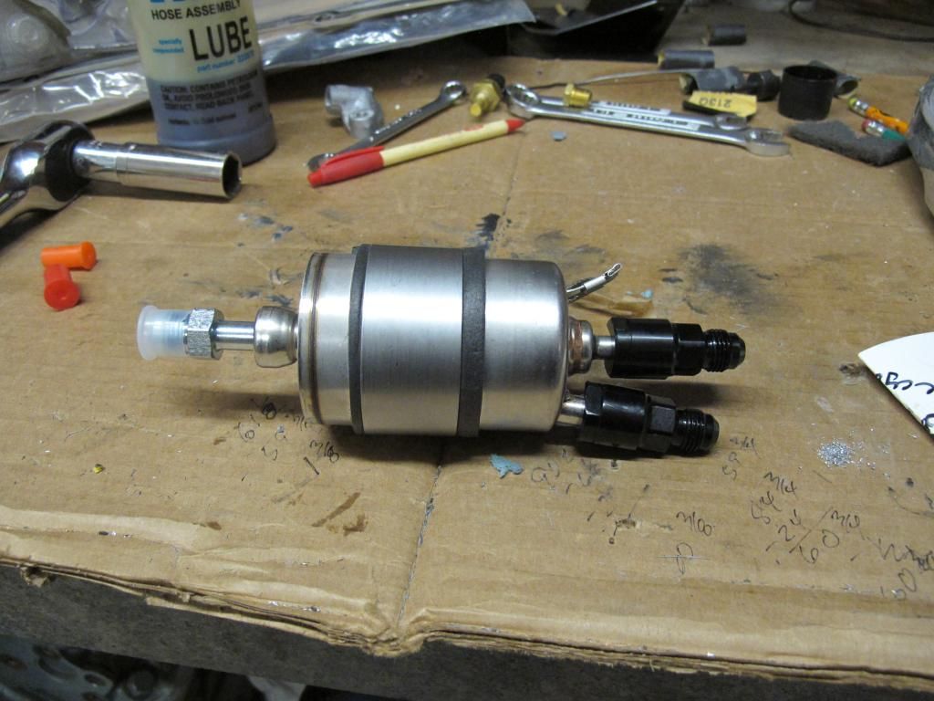
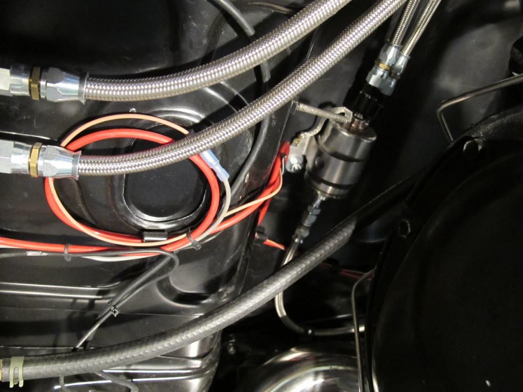
I really like the TFE hose. The ends are super simple to assemble and by running a continuous run of hose from the regulator to the engine, I minimize potential leaks. All clamped off for a clean installation
Long weekend in the garage with some decent results.
I got the Radaflex 1/0 donkey dick starter cable from Cable Yard and I got that ran that on the passenger side from the trunk to the starter. Waiting on the hydraulic crimper to arrive and I can go to town terminating the cable. I was going to mount the battery on the passenger side of the trunk, but I am seriously considering running a spare tire and the factory spare hook is still in the trunk which makes the location ideal for the spare. With the LS, I plan on driving this thing a bunch more and I really want a spare for the piece of mind. Just need to find a 04-06 GTO spare - close fit...enough to get me where I need to go.
Next on task was to figure out a bracket to mount my proportioning valve and the clutch master reservoir. I opted for a Ring Brothers billet deal which is killer and only a few bucks more than a plain plastic deal. I knew I wanted everything to be located on the brake master cylinder to keep the firewall clean. Starting with some poster board templates, I played around with some patterns. Using some 0.090" aluminum I had sitting around, this is what I came up with. Pretty clean installation


I made up some wire templates for brake lines and I like stainless so I will be shipping these templates off to Right Stuff to have them bend them up for me.
Next on tap was to tackle the clutch pedal mods. I have played around with this before and knew that I could not do a simple heim joint at the clutch pedal because the pedal and the clutch master are not in perfect alignment. Side load is death to a master and so I needed another solution. SOOOOOOO...What to do?
Starting with a piece of 1/4" X 1" flat stock, I welded a long rod nut to the flat stock. I then drilled a hole in the end of the stock for a pivot point.

Because of hydraulic setup does not have as much of an angle as the mechanical setup, I had to make a bracket that relocates the pivot point lower on the clutch pedal. As mentioned earlier, the clutch pedal is not in alignment with the master rod. With the new push rod bracket and the clutch pedal adapter piece, I end up needing only a 0.030" thick washer to get the push rod dead nuts in alignment with the clutch master. For the vertical angle, i used my Wixley digital angle finder to match angles between the master body and the input shaft. The angle finder is very compact and I was able to measure the angle off of the master body and the input rod and set the two equal to each other. I plan on adding a bronze bushing for the pivot pin.

I also made a clutch pedal stop and welded that to the clutch pedal. Just need to find a bumper and a 5/16" rod.

Next up was to make an adapter plate for the crossmember to the transmission mount. Using 3/8" plate, I welded up a couple of pieces of steel and finished them off with a grinder.

Last weekend: I got my order of Aeroquip parts from the Hose Warehouse a week or so ago and plumbed up the Corvette style regulator. Just wished that the input and the return were separated a bit more.


I really like the TFE hose. The ends are super simple to assemble and by running a continuous run of hose from the regulator to the engine, I minimize potential leaks. All clamped off for a clean installation


 11-30-2014, 07:32 PM
#23
Thanks...
I would like to say that I got a ton done this weekend...but that is not the case. I got my new battery cable crimper off of ebay and was able to crimp the end of the 1/0 at the starter. Didn't like the wire templates for the brake lines so I bought some brake line from Farm and Fleet and spent some time bending up with lines to be used as templates for the stainless. Glad i did because when I checked the final design against the wire templates, I was off a bunch with all of them. No biggie...I have about $10 into the brake line.
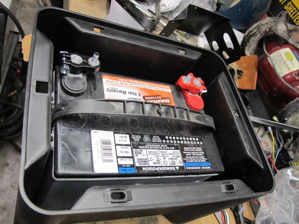
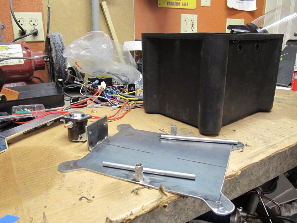
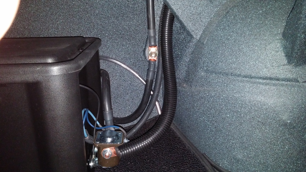
I have a Duration AGM battery from Farm and Fleet that is about 2 years old and has been flawless. Like the Optima, it is sealed, but there is the potential of out gassing on overcharging. Optima even says that their AGM style batteries should be put in a battery box with a vent to the outside when installed in a trunk. SO...I bought a Moroso battery box and decided to mount the battery in the trunk. The directions say to pop two 3/8" holes through the trunk floor and use the threaded rod included in the kit to hold it down. The engineer in me said that was kind of hookie so I decided to engineer a mounting plate to create 4 mounting points instead of 2. Using the box as a template, I made the plate out of 10 gauge and welded two coupler nuts to the plate for the hold down. My cheapie Horrible Freight steel band saw made quick work of this. Using four 1/4-20 bolts at each corner, this will be a more secure solution. I even included a small bracket on the side of the box for the starter solenoid. I like the idea of using a box because it finishes off the trunk better and protects against incidental shorting of the battery terminals. Using top post
Keep on plugging away.
I would like to say that I got a ton done this weekend...but that is not the case. I got my new battery cable crimper off of ebay and was able to crimp the end of the 1/0 at the starter. Didn't like the wire templates for the brake lines so I bought some brake line from Farm and Fleet and spent some time bending up with lines to be used as templates for the stainless. Glad i did because when I checked the final design against the wire templates, I was off a bunch with all of them. No biggie...I have about $10 into the brake line.
I have a Duration AGM battery from Farm and Fleet that is about 2 years old and has been flawless. Like the Optima, it is sealed, but there is the potential of out gassing on overcharging. Optima even says that their AGM style batteries should be put in a battery box with a vent to the outside when installed in a trunk. SO...I bought a Moroso battery box and decided to mount the battery in the trunk. The directions say to pop two 3/8" holes through the trunk floor and use the threaded rod included in the kit to hold it down. The engineer in me said that was kind of hookie so I decided to engineer a mounting plate to create 4 mounting points instead of 2. Using the box as a template, I made the plate out of 10 gauge and welded two coupler nuts to the plate for the hold down. My cheapie Horrible Freight steel band saw made quick work of this. Using four 1/4-20 bolts at each corner, this will be a more secure solution. I even included a small bracket on the side of the box for the starter solenoid. I like the idea of using a box because it finishes off the trunk better and protects against incidental shorting of the battery terminals. Using top post


Keep on plugging away.
Last edited by old66tiger; 04-22-2015 at 10:49 AM.
03-01-2015, 10:06 PM
#25
So…it has been awhile since my last update. Lots going on and things just got side tracked. Here is my mass update.
I am using the Holley 302-1 pan and I decided to stick the pan to the engine for the last time. Using the Holley o ring on the pickup tube, I installed the tube to the oil pump. Observation: the Holley oring is not as pliable as the GM oring, but it is smaller and more compatible with the shape of the tube. The tube is held in with a single 6 mm bolt. Instead of using the shorter Holley bolts supplied with the kit, I used the GM bolt because it was longer and has more thread engagement – which should ultimately be better. I will be the first to say that my OCD was probably kicking into high gear during this part, but every time I started to torque the 6 mm bolt to 106 in-lbs, I had this sinking feeling that the threads were starting to let loose. I must have backed this thing out 5 times, inspected threads. Everything looked good, but being somewhat paranoid and unwilling to have to replace the pump because of messed up threads, I decided to use my dial torque wrench instead of the clicker. I bought this torque wrench a few years back at a swap meet. It is nice USA quality and when I checked the calibration, it was pretty damn close. So, with some blue thread locker on the threads, I ran the screw up and used the dial torque wrench to creep up on the 106 in-lbs. As soon as I hit the mark, I got off of it and called it good enough.
I opted for the trap door baffle and when I installed that in the pan, it did not fit. The assembly was too tall and it did not sit down on the mounting bosses – leaving about 1/8” of space. I called Holley and of course, they were surprised that it did not fit. HAHA. I wasn’t. Instead of dicking around with getting a new one, I elected to trim 1/8” off of the bottom of the baffle assembly to allow it to sit on the mounting bosses flat. 60 minutes of careful grinding and fitting, I had it perfect. I installed the bellhousing to the engine and then installed the oil pan. I used the two lower oil pan bolts to pull the pan tight to the bellhousing and then torqued the oil pan bolts. The two 6 MM bolts on the rear of the pan were my nemesis….again used the dial torque wrench to tighten these. Did I mention that I hate aluminum and super paranoid of stripping threads????
Installed the pilot bearing so I anti-seized the register and tapped it in with a large socket. After it was in, it wasn’t as smooth as I thought it should be and I elected to get another. I tried pulling this thing out with my little slide hammer and that was useless. So I took a trip to Autozone and rented a blind hole puller to pull the pilot bearing. That thing worked slick! SO…word to the wise, if you have to pull a pilot bearing, rent this tool and your life will be a lot easier. Froze the bearing overnight and tapped the new one home. Perfect! Threw the bell housing on and slid the trans in to make sure that there wasn’t any pilot interference. Looks good.
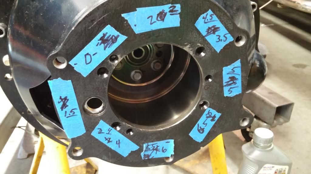
So…I made several checks on the bellhousing to make sure that everything was perfectly flat and true. With the bellhousing torqued to the block, I set up my dial indicator to measure parallel. My first measurement showed the the bell was out of true about 0.008” – which is greater than the 0.002-0.003” spec. I called Quick Time and they said that these bells are trued up on a broach before they are powder coated and sent out the door. He suggested to block sand the engine block and both sides of the bell to ensure that there is no “junk” pushing on the bell. 400 grit on a wood block made short work of this and the subsequent indicator read 0.0025” within parallel. Good enough. Time to check input shaft alignment - With my dial indicator on the crank, I measured 0.011” run out of the bell register. Offsets are needed to get it within the 0.010” maximum. I made a call to RobbMc and he sent out a set of 0.007” offset dowels for the GM housings. Popped out the old dowels and threw these in and my measurement went from 0.011” low to 0.010” high. What the heck! I checked this thing several times and it came out vastly different than what I was expecting. Thinking that maybe the factory dowels were just too short, I ordered up a set of Moroso extra-long straights. Popped them in and I came within 0.006”. Just as I was thinking that I was done with this deal, I pulled the bell housing bolts off and as I removed the last bolt, the bell fell off the motor. This got me to thinking that there was something wrong with the bell. I checked the pins and they came out at 0.6205. I checked the bell housing and that came out at 0.630”. Almost 0.010” too big. I checked my old POS Pontiac bell and that indicated at 0.625”. Just for grins, I tried fitting the Pontiac bell on the LS motor and it slid on tight but was snug like it is supposed to be. After talking with Ross McCombs at Quicktime, he had me send the bell back for inspection. They have no idea how it got machined that loose, but none the less, they are going to fix it and make sure that it measures right to spec. At least this explains the erratic measurements..
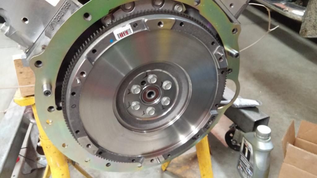
I also checked the flywheel to see how true it is. I am using the LS7 flywheel and torqued to spec using the old bolts. I block sanded the crank flange and the back side of the flywheel first to make sure there were no burrs. Dial indicator came within 0.0045” total run out. Not ideal, but by Poncho was 0.006” and I never had any problems. Good enough
I am using the Holley 302-1 pan and I decided to stick the pan to the engine for the last time. Using the Holley o ring on the pickup tube, I installed the tube to the oil pump. Observation: the Holley oring is not as pliable as the GM oring, but it is smaller and more compatible with the shape of the tube. The tube is held in with a single 6 mm bolt. Instead of using the shorter Holley bolts supplied with the kit, I used the GM bolt because it was longer and has more thread engagement – which should ultimately be better. I will be the first to say that my OCD was probably kicking into high gear during this part, but every time I started to torque the 6 mm bolt to 106 in-lbs, I had this sinking feeling that the threads were starting to let loose. I must have backed this thing out 5 times, inspected threads. Everything looked good, but being somewhat paranoid and unwilling to have to replace the pump because of messed up threads, I decided to use my dial torque wrench instead of the clicker. I bought this torque wrench a few years back at a swap meet. It is nice USA quality and when I checked the calibration, it was pretty damn close. So, with some blue thread locker on the threads, I ran the screw up and used the dial torque wrench to creep up on the 106 in-lbs. As soon as I hit the mark, I got off of it and called it good enough.
I opted for the trap door baffle and when I installed that in the pan, it did not fit. The assembly was too tall and it did not sit down on the mounting bosses – leaving about 1/8” of space. I called Holley and of course, they were surprised that it did not fit. HAHA. I wasn’t. Instead of dicking around with getting a new one, I elected to trim 1/8” off of the bottom of the baffle assembly to allow it to sit on the mounting bosses flat. 60 minutes of careful grinding and fitting, I had it perfect. I installed the bellhousing to the engine and then installed the oil pan. I used the two lower oil pan bolts to pull the pan tight to the bellhousing and then torqued the oil pan bolts. The two 6 MM bolts on the rear of the pan were my nemesis….again used the dial torque wrench to tighten these. Did I mention that I hate aluminum and super paranoid of stripping threads????

Installed the pilot bearing so I anti-seized the register and tapped it in with a large socket. After it was in, it wasn’t as smooth as I thought it should be and I elected to get another. I tried pulling this thing out with my little slide hammer and that was useless. So I took a trip to Autozone and rented a blind hole puller to pull the pilot bearing. That thing worked slick! SO…word to the wise, if you have to pull a pilot bearing, rent this tool and your life will be a lot easier. Froze the bearing overnight and tapped the new one home. Perfect! Threw the bell housing on and slid the trans in to make sure that there wasn’t any pilot interference. Looks good.

So…I made several checks on the bellhousing to make sure that everything was perfectly flat and true. With the bellhousing torqued to the block, I set up my dial indicator to measure parallel. My first measurement showed the the bell was out of true about 0.008” – which is greater than the 0.002-0.003” spec. I called Quick Time and they said that these bells are trued up on a broach before they are powder coated and sent out the door. He suggested to block sand the engine block and both sides of the bell to ensure that there is no “junk” pushing on the bell. 400 grit on a wood block made short work of this and the subsequent indicator read 0.0025” within parallel. Good enough. Time to check input shaft alignment - With my dial indicator on the crank, I measured 0.011” run out of the bell register. Offsets are needed to get it within the 0.010” maximum. I made a call to RobbMc and he sent out a set of 0.007” offset dowels for the GM housings. Popped out the old dowels and threw these in and my measurement went from 0.011” low to 0.010” high. What the heck! I checked this thing several times and it came out vastly different than what I was expecting. Thinking that maybe the factory dowels were just too short, I ordered up a set of Moroso extra-long straights. Popped them in and I came within 0.006”. Just as I was thinking that I was done with this deal, I pulled the bell housing bolts off and as I removed the last bolt, the bell fell off the motor. This got me to thinking that there was something wrong with the bell. I checked the pins and they came out at 0.6205. I checked the bell housing and that came out at 0.630”. Almost 0.010” too big. I checked my old POS Pontiac bell and that indicated at 0.625”. Just for grins, I tried fitting the Pontiac bell on the LS motor and it slid on tight but was snug like it is supposed to be. After talking with Ross McCombs at Quicktime, he had me send the bell back for inspection. They have no idea how it got machined that loose, but none the less, they are going to fix it and make sure that it measures right to spec. At least this explains the erratic measurements..
I also checked the flywheel to see how true it is. I am using the LS7 flywheel and torqued to spec using the old bolts. I block sanded the crank flange and the back side of the flywheel first to make sure there were no burrs. Dial indicator came within 0.0045” total run out. Not ideal, but by Poncho was 0.006” and I never had any problems. Good enough

Last edited by old66tiger; 04-10-2015 at 02:32 PM.
03-01-2015, 10:14 PM
#26
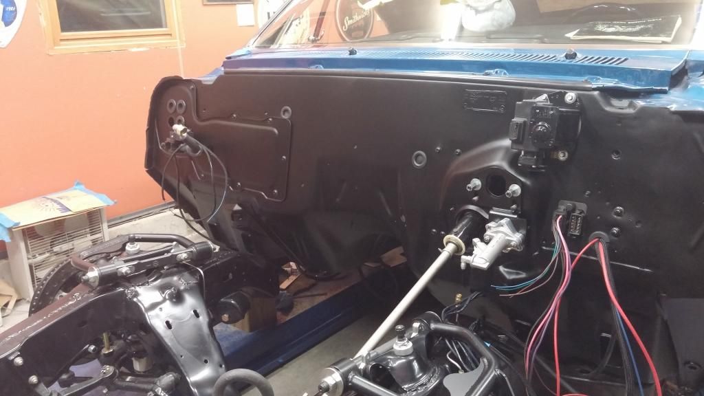
So, I was not perfectly happy with the last paint job on the firewall and elected to wet sand it flat and give it another shot. I had my body shop buddy come back down and re-shoot the entire firewall. It turned out very nice. The SEM Hot Rod black is very consistent and durable. Re-painted the wiper motor and installed it and the cowl screen. I got some button head cap screws, painted them and installed the heater delete plate.
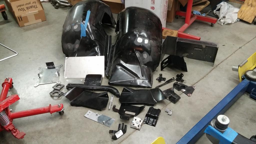
Got all of my parts ready for the powder coater. I chose matte black to get close to the firewall color. The color came out a bit shiny. I may opt for scuffing the tubs and the core and hit it with hot rod black
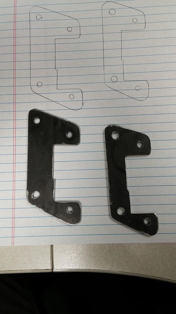
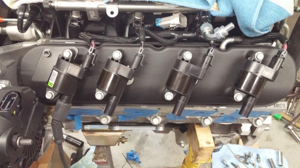
I bought a set of the Holley Valve covers. The first set of covers had loose vent tube holes and I called Summit and they sent out another set right away. The second set was better. The finish is not black crinkle like they lead you to believe. It is more like a black powder coat. The #1 coil does not fit in the stock location due to high mount alternator. They give you a bracket to offset if from the alternator, but this only works on flat style coils.
I called Holley, and the response was like I expected…no solution. So, I took matters into my own hands and made my own bracket. I sent Holley my drawing and I got no thank you for my efforts. I would have expected a t-shirt at a minimum.
Sent the LGT-700 back to Legend Gear and Transmission. I had a slight noise in 4th gear and the shifter centering spring wasn’t as tight as I would have liked. They sent a call tag out and turned this in about a week. WOW! What customer service. Jack Simms and the boys at Legend are a first class act. They replaced a few parts with updated pieces and put stiffer springs in the shifter. Time will tell if it is good to go, but I am confident that if there is any issues, they are here to take care of things. Highly recommended.
So, this whole process got slowed down by several factors….holidays, Cub Scout den leader responsibilities, the need to repaint the firewall….and one of my closest friends passed away unexpectedly a few days before my 48th b-day. My buddy John was 50 years old and in perfect health. Avid weight lifter, moto X racer and was probably in better shape than most guys that are in their 30’s. He dominated local races and was forced to race in the older leagues to give the younger guys a chance at competing. Active, jovial and an overall great guy – you would rarely hear him say anything bad about someone. John had a major brain aneurysm that ended his life quickly. We had talked 30 minutes prior to this event and he was perfectly fine…no warning signs. The only positive thing that came out of this was that he was in such great health, his donor signature allowed him to donate his kidneys, liver, lungs, heart, corneas, and skin – not sure if I missed anything. His gracious gifts saved the lives of 6 individuals that will probably never know how wonderful he was. The heart went to a 60 year old vet that very night. John leaves behind a wife of 30 years and a legacy of giving and helping anyone that needed a helping hand. Truly a legacy that many strive for, but few actually achieve. He leaves a hole behind as he was a helpful hand and a true friend. He lived 1 mile from my house and we were always helping each other out. Most work sessions ended in a minimum of an hour of bull$hit that had both of us in stitches. It sucks when many a$$holes live forever and the good ones exit before the rest of us are ready to let go. RIP Johnny.

Got all of my parts ready for the powder coater. I chose matte black to get close to the firewall color. The color came out a bit shiny. I may opt for scuffing the tubs and the core and hit it with hot rod black

I bought a set of the Holley Valve covers. The first set of covers had loose vent tube holes and I called Summit and they sent out another set right away. The second set was better. The finish is not black crinkle like they lead you to believe. It is more like a black powder coat. The #1 coil does not fit in the stock location due to high mount alternator. They give you a bracket to offset if from the alternator, but this only works on flat style coils.

I called Holley, and the response was like I expected…no solution. So, I took matters into my own hands and made my own bracket. I sent Holley my drawing and I got no thank you for my efforts. I would have expected a t-shirt at a minimum.


Sent the LGT-700 back to Legend Gear and Transmission. I had a slight noise in 4th gear and the shifter centering spring wasn’t as tight as I would have liked. They sent a call tag out and turned this in about a week. WOW! What customer service. Jack Simms and the boys at Legend are a first class act. They replaced a few parts with updated pieces and put stiffer springs in the shifter. Time will tell if it is good to go, but I am confident that if there is any issues, they are here to take care of things. Highly recommended.
So, this whole process got slowed down by several factors….holidays, Cub Scout den leader responsibilities, the need to repaint the firewall….and one of my closest friends passed away unexpectedly a few days before my 48th b-day. My buddy John was 50 years old and in perfect health. Avid weight lifter, moto X racer and was probably in better shape than most guys that are in their 30’s. He dominated local races and was forced to race in the older leagues to give the younger guys a chance at competing. Active, jovial and an overall great guy – you would rarely hear him say anything bad about someone. John had a major brain aneurysm that ended his life quickly. We had talked 30 minutes prior to this event and he was perfectly fine…no warning signs. The only positive thing that came out of this was that he was in such great health, his donor signature allowed him to donate his kidneys, liver, lungs, heart, corneas, and skin – not sure if I missed anything. His gracious gifts saved the lives of 6 individuals that will probably never know how wonderful he was. The heart went to a 60 year old vet that very night. John leaves behind a wife of 30 years and a legacy of giving and helping anyone that needed a helping hand. Truly a legacy that many strive for, but few actually achieve. He leaves a hole behind as he was a helpful hand and a true friend. He lived 1 mile from my house and we were always helping each other out. Most work sessions ended in a minimum of an hour of bull$hit that had both of us in stitches. It sucks when many a$$holes live forever and the good ones exit before the rest of us are ready to let go. RIP Johnny.
Last edited by old66tiger; 04-10-2015 at 02:34 PM.
04-20-2015, 12:56 PM
#27
Another mass update:
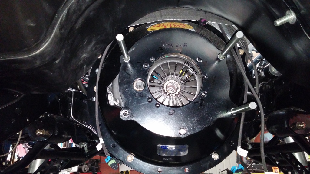
Well…the re-worked bellhousing turned out to be a bunch of messing around for nothing. It came back still fitting a bit loose. I contacted Bowler and they sent me another QuickTime and an Aluminum bellhousing to try. The new QuickTime came in within 0.004” right out of the box and the aluminum one was 0.011”. I opted for the QuickTime and installed the clutch and torqued everything to spec. Flywheel bolts are torqued in 3 increments of 15, 37 and 74 ft-lbs and the pressure plate is installed at 37 ft-lbs. I bought a ram clutch installation tool to set up the clutch and the pilot of the tool as 0.0005” too big. Some time with 400 grit sand paper pulled the 0.0005” out and it works pretty slick.
Measured clutch finger depth and found that the fingers vary 0.040” from the highest to the lowest finger. After talking with GM and Bowler, this apparently is not all that uncommon. So, I set the clutch up for 0.155” on the tightest to 0.195” on the loosest setting. I had to grind down the bearing retainer bolts on the transmission to clear the bearing housing.
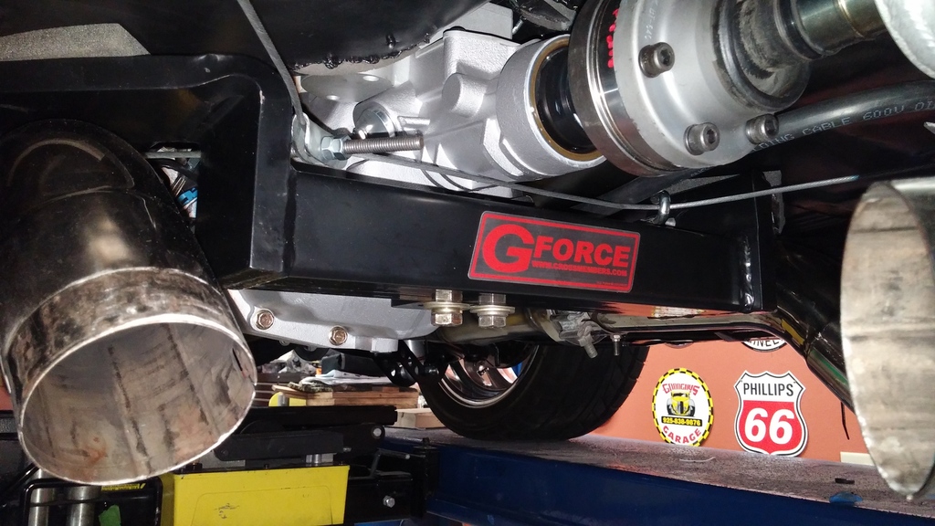
After stabbing in the motor for the last time, I opted to install spacer plates under the motor mount adapters to gain another 0.100” clearance between the frame and the oil pan. Harder with the motor in, but I got it. I learned long ago that you cannot stab a motor and trans in this car as a complete assembly without running into interference issues. So, after installing the motor, I installed the transmission. Here is a valuable tech tip. Buy 6” long ˝” bolts and cut the heads off to use them as guide bolts. The Tilton bearing is a bitch to install with the trans without these as guide pins. Makes short work out of the operation.
Installed the cross member for the last time and torqued to spec.
I had a buddy come down and help with installing the front end sheet metal and that set the rest of the parts in motion for the race to the end
Installed clutch and master with the hydratech booster and bled all systems out.
Installed pedals in the car and made up a firewall gasket for the clutch out of a piece of pond liner rubber. Nothing complicated and should work fine.
Installed the Dynamat firewall pad using the self-adhesive backing. I was skeptical, but it seemed to work fine. Nothing really unique to see here. Just take your time and make a template so it drops into the car. Installed the vintage air unit for the last time.
I opted to run one of the heater lines out the block off plate and mount the heater control valve on the firewall delete plate. I drilled four holes in the side of the cowl for the AC lines, heater hose and the electrical connections for the AC compressor, heater control valve and the O2 meter for the LM2. Lots of head scratching to make sure that these came out in the correct spot. I welded a nut on the top side of the vintage air bracket so that the top bolt could be easily installed from the engine compartment. The bottom bolt didn’t need that so I did not bother with that. Being somewhat cocky, I thought that installing the AC and heater lines with the box mounted in the car was going to be easy….boy, was I mistaken. A trip to Menards and I bought some cheapie wrenches that I heated up with the torch and bent into custom installation tools. You can see where the one AC service port is hidden behind the fender and the other is down low. The one inside the fender has enough slack to pull out to attach the adapter.
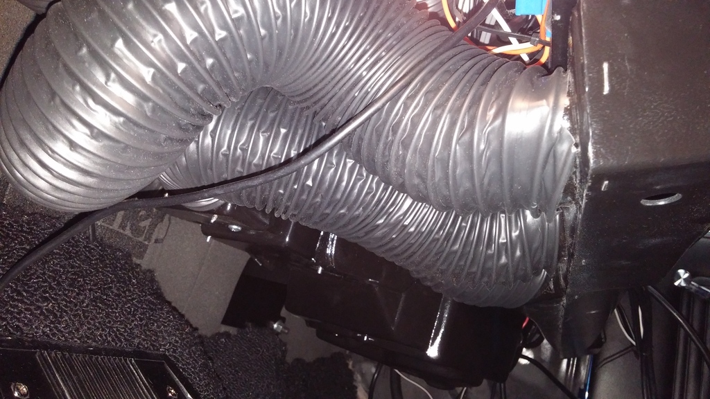
Installed the heater vent tubing and learned that the best way to hide the tubing is to twist it when installing it and it will draw up neatly into the dash.
Ran the wiring to the driver’s side of the car and passed it out into the engine compartment to the main panel.
More on the AC lines later.
Well…the re-worked bellhousing turned out to be a bunch of messing around for nothing. It came back still fitting a bit loose. I contacted Bowler and they sent me another QuickTime and an Aluminum bellhousing to try. The new QuickTime came in within 0.004” right out of the box and the aluminum one was 0.011”. I opted for the QuickTime and installed the clutch and torqued everything to spec. Flywheel bolts are torqued in 3 increments of 15, 37 and 74 ft-lbs and the pressure plate is installed at 37 ft-lbs. I bought a ram clutch installation tool to set up the clutch and the pilot of the tool as 0.0005” too big. Some time with 400 grit sand paper pulled the 0.0005” out and it works pretty slick.
Measured clutch finger depth and found that the fingers vary 0.040” from the highest to the lowest finger. After talking with GM and Bowler, this apparently is not all that uncommon. So, I set the clutch up for 0.155” on the tightest to 0.195” on the loosest setting. I had to grind down the bearing retainer bolts on the transmission to clear the bearing housing.
After stabbing in the motor for the last time, I opted to install spacer plates under the motor mount adapters to gain another 0.100” clearance between the frame and the oil pan. Harder with the motor in, but I got it. I learned long ago that you cannot stab a motor and trans in this car as a complete assembly without running into interference issues. So, after installing the motor, I installed the transmission. Here is a valuable tech tip. Buy 6” long ˝” bolts and cut the heads off to use them as guide bolts. The Tilton bearing is a bitch to install with the trans without these as guide pins. Makes short work out of the operation.

Installed the cross member for the last time and torqued to spec.

I had a buddy come down and help with installing the front end sheet metal and that set the rest of the parts in motion for the race to the end
Installed clutch and master with the hydratech booster and bled all systems out.
Installed pedals in the car and made up a firewall gasket for the clutch out of a piece of pond liner rubber. Nothing complicated and should work fine.

Installed the Dynamat firewall pad using the self-adhesive backing. I was skeptical, but it seemed to work fine. Nothing really unique to see here. Just take your time and make a template so it drops into the car. Installed the vintage air unit for the last time.
I opted to run one of the heater lines out the block off plate and mount the heater control valve on the firewall delete plate. I drilled four holes in the side of the cowl for the AC lines, heater hose and the electrical connections for the AC compressor, heater control valve and the O2 meter for the LM2. Lots of head scratching to make sure that these came out in the correct spot. I welded a nut on the top side of the vintage air bracket so that the top bolt could be easily installed from the engine compartment. The bottom bolt didn’t need that so I did not bother with that. Being somewhat cocky, I thought that installing the AC and heater lines with the box mounted in the car was going to be easy….boy, was I mistaken. A trip to Menards and I bought some cheapie wrenches that I heated up with the torch and bent into custom installation tools. You can see where the one AC service port is hidden behind the fender and the other is down low. The one inside the fender has enough slack to pull out to attach the adapter.


Installed the heater vent tubing and learned that the best way to hide the tubing is to twist it when installing it and it will draw up neatly into the dash.

Ran the wiring to the driver’s side of the car and passed it out into the engine compartment to the main panel.
More on the AC lines later.
Last edited by old66tiger; 04-22-2015 at 10:54 AM.
04-20-2015, 01:05 PM
#28
Next up was to install the harness. I had Speartech make up a custom length harness for me because I wanted to mount the ECM behind the driver’s side headlight. I am pretty satisfied with the quality and the fit of the harness. I had to send it back to shorten the power lead, but the overall fit was very nice.
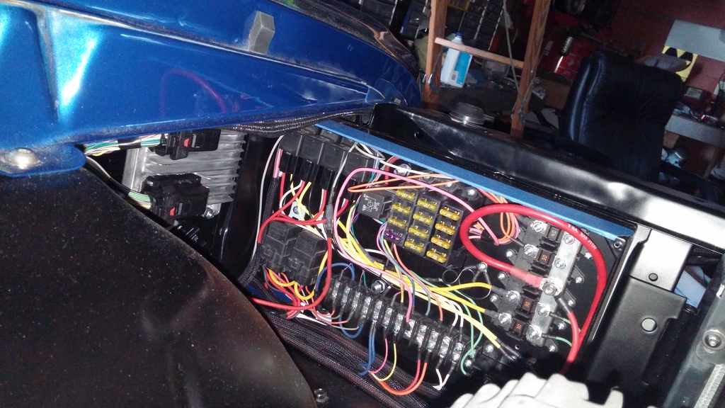
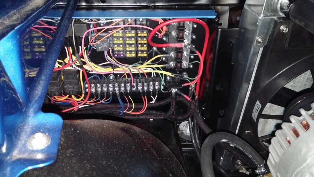
Installed my main power distribution panel behind the headlight. All wiring with the exception of the AC fuse and the power top fuse go to this panel. The AC and power top fuses are tucked up under the fender in a separate panel. Before making up the panel, I created a wiring diagram to give me some sort of road map for everything. I adjusted this as I added things and when I was fairly certain that this was set in stone, I laid everything out for the last time. Lots of wiring, but once the cover is on it will be invisible. The alternator main wire is run right to the buss bar and I have a thick 8 gauge wire running to the trunk for the charge circuit and another running from the main panel to the AC and Power top panel. My main fuse block for the various accessory functions along with the Speartech fuse block look nice in here.
After I installed the main panel, I noticed that the panel was almost touching the inside of the fender. Too close for comfort, so I cut an inch out of the end of the panel and moved the ECM in a bit. Fits and functions perfect now. Here is a shot of the panel internals and the ECM placement
I wired the AC trinary switch to operate both fans at once which will also result in both fans turning on with the ECM because of the common ground connection. I ran the trinary wires along side of the front end headlight wires. Notice that I also included a Ľ” ground stud for a 4 gauge ground from the engine to the panel. Additional grounds were installed on the core support for the headlights.
Installed the oil separator on the front of the motor and plumbed it in.
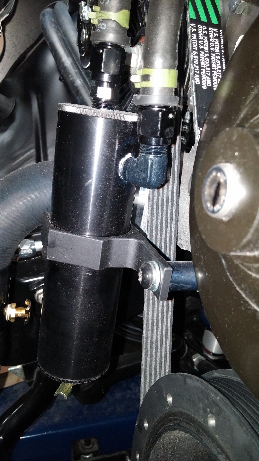
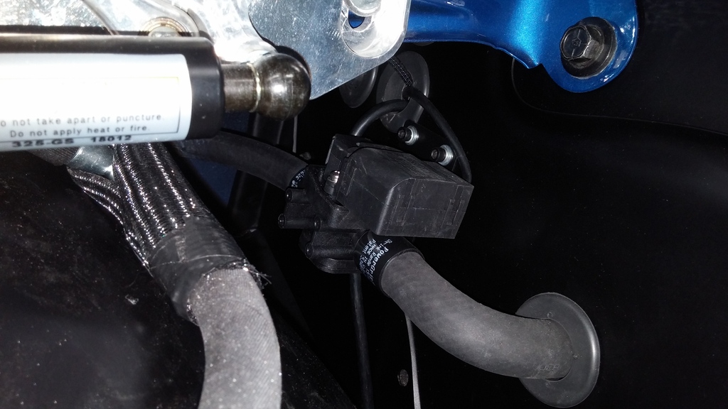
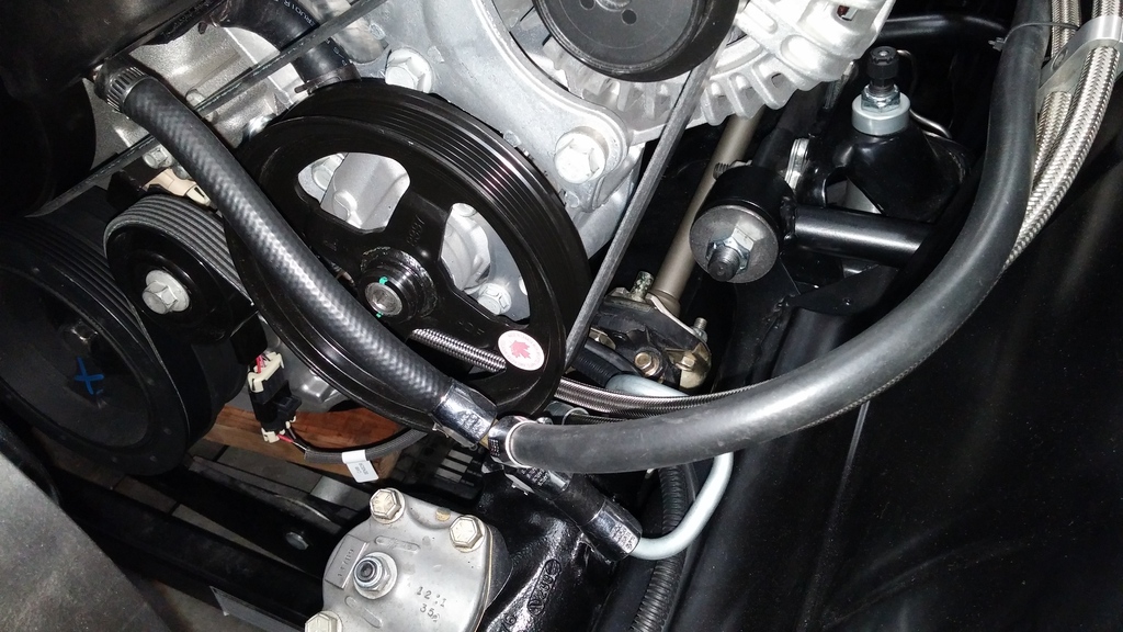
With some minor rework of the old PS lines, I installed the PS pump and the hydraboost. I made a custom return line to dress things up a bit
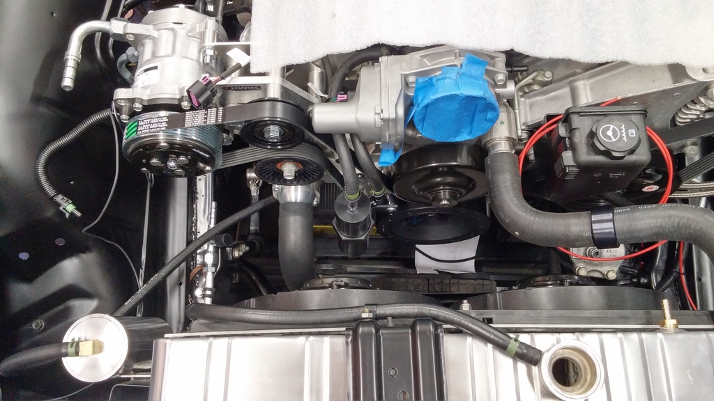
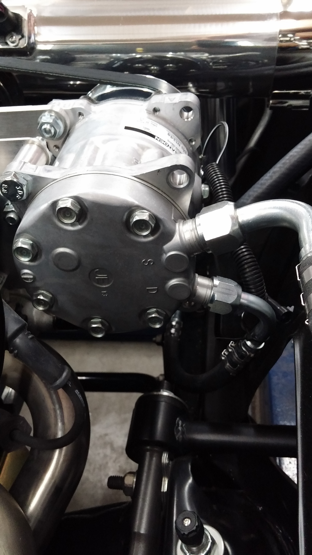
Installed the AC compressor with the inlet and outlet clocked 90 degrees from vertical. According to vintage air, this is OK. Can’t install upside down. The inlet and outlet just clear the inner fender. I had to install in-line service ports due to the lack of space at the inner fender. I could have opted for installing the compressor at the normal vertical location, but that just looked odd.
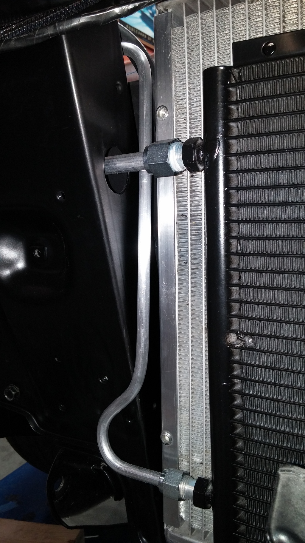
Installed the condenser and quickly noticed that the lines that came with the condenser were not going to work. So, I opted for the u-bend lines and fabricated my own. I think it turned out fantastic. I drilled the hole like they called for in the instructions and that worked well for the #8 going into the condenser. The #6 was routed straight out of the top and runs directly into the aluminum drier. I like the look of this better than the steel or chrome units.
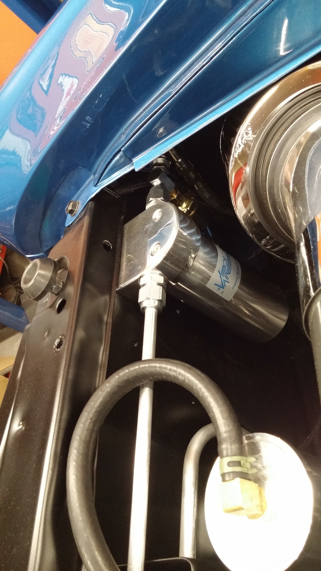
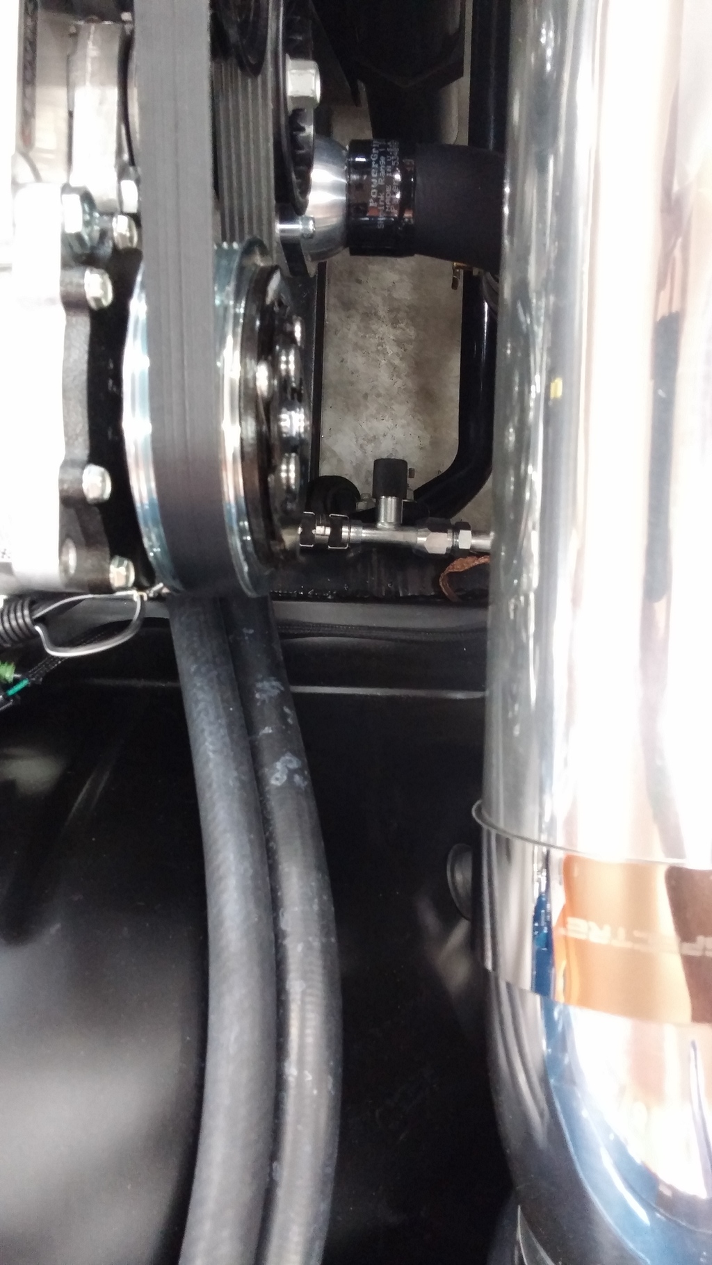
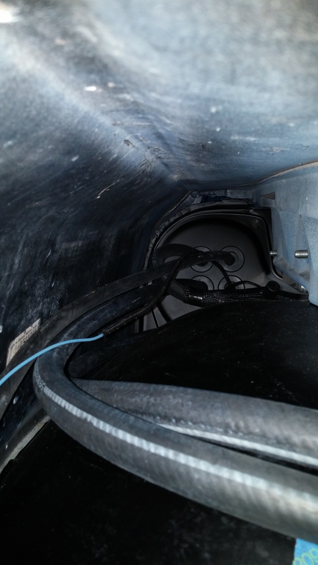
After getting the hard lines bent, I opted for the EZ clip hose and fittings for the rest. WOW! These things are a breeze to install. In addition, you can clock it where you want them and snap the clips – presto. I elected to put the high side port down along the frame and secure the line with a clamp. The low side port is located under the PS fender and is easily accessible by pulling 6” out of the fender. When done, just slide it back under the fender.
Grounds….I cannot say enough about good grounds. I welded a stud in the trans tunnel and ran a 1/0 from there to the PS head. I also ran a 1/0 from the trunk directly up to the DS head. I wanted redundancy with the batter back in the trunk and this was the best solution I could come up with.
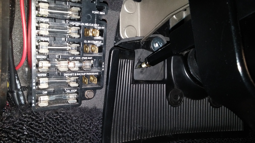
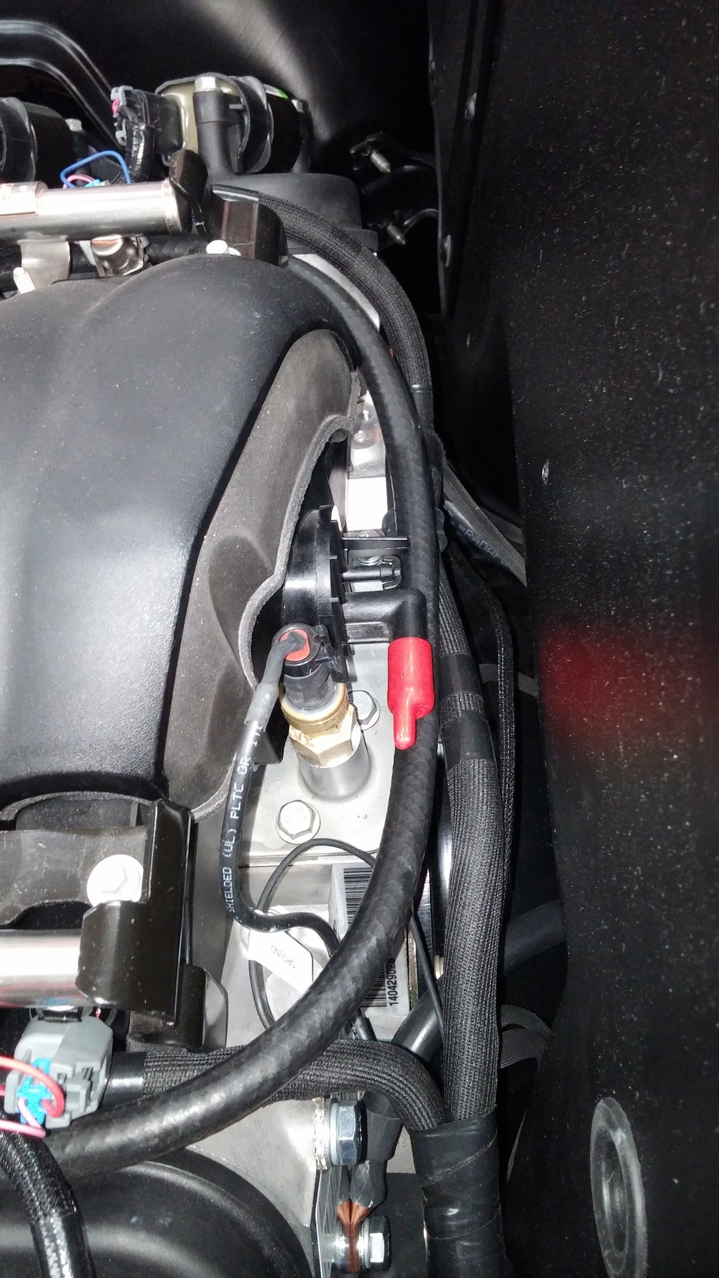
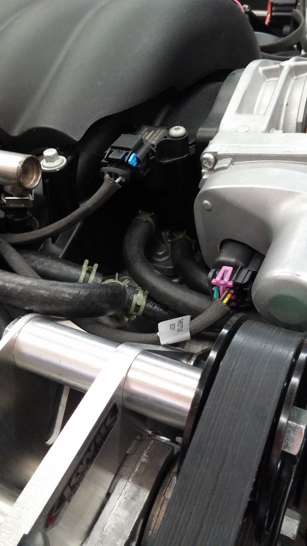
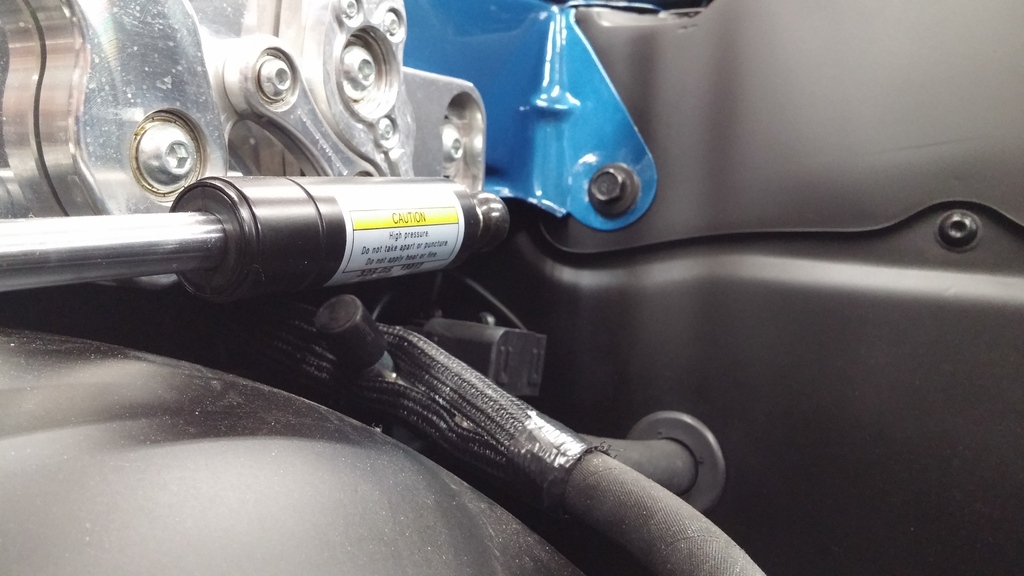
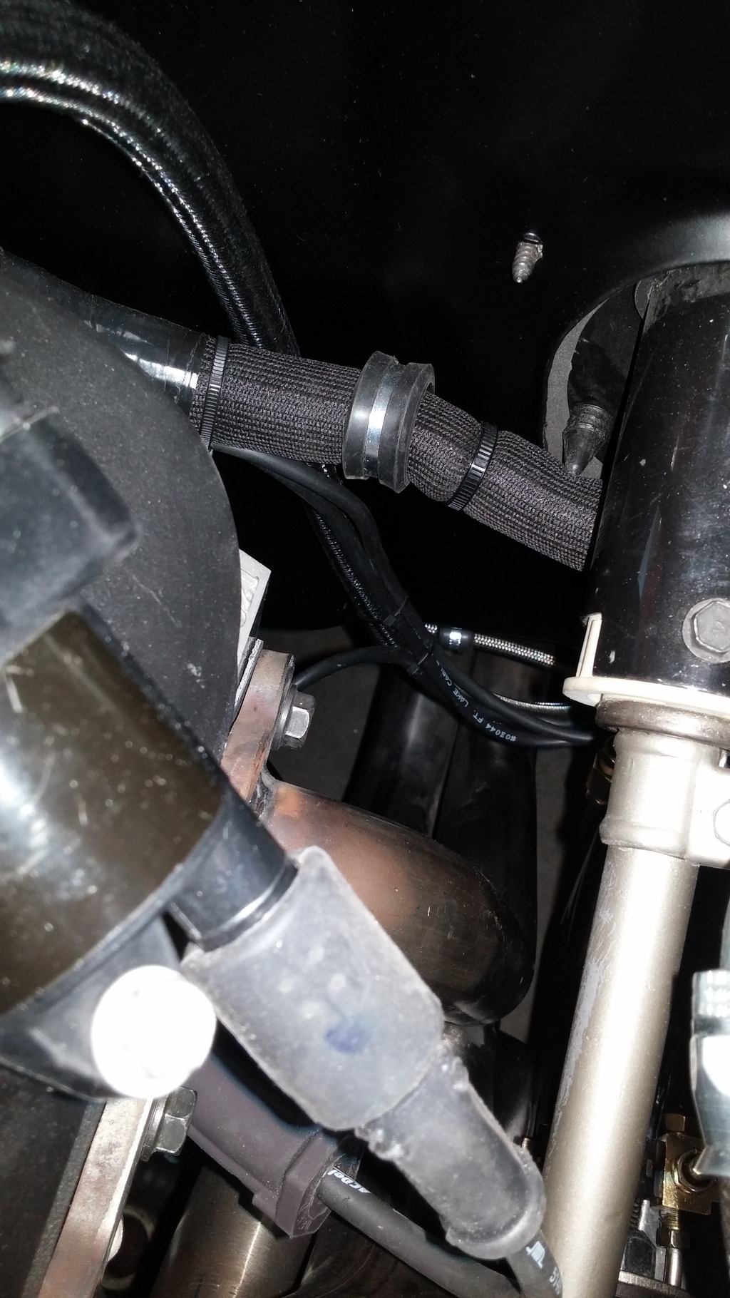
Finished running the brake lines, bench bled the master and installed everything to finish bleeding on the car. I opted for a braided clutch hose and clamped everything off to ensure that I had no issues with things moving around. Last thing I need is for lines to come in contact with the exhaust. Notice the harness is clamped to the firewall and the fuel line runs behind it. The clutch line is clamped below it. Might be hard to see here

Installed my main power distribution panel behind the headlight. All wiring with the exception of the AC fuse and the power top fuse go to this panel. The AC and power top fuses are tucked up under the fender in a separate panel. Before making up the panel, I created a wiring diagram to give me some sort of road map for everything. I adjusted this as I added things and when I was fairly certain that this was set in stone, I laid everything out for the last time. Lots of wiring, but once the cover is on it will be invisible. The alternator main wire is run right to the buss bar and I have a thick 8 gauge wire running to the trunk for the charge circuit and another running from the main panel to the AC and Power top panel. My main fuse block for the various accessory functions along with the Speartech fuse block look nice in here.
After I installed the main panel, I noticed that the panel was almost touching the inside of the fender. Too close for comfort, so I cut an inch out of the end of the panel and moved the ECM in a bit. Fits and functions perfect now. Here is a shot of the panel internals and the ECM placement

I wired the AC trinary switch to operate both fans at once which will also result in both fans turning on with the ECM because of the common ground connection. I ran the trinary wires along side of the front end headlight wires. Notice that I also included a Ľ” ground stud for a 4 gauge ground from the engine to the panel. Additional grounds were installed on the core support for the headlights.

Installed the oil separator on the front of the motor and plumbed it in.


With some minor rework of the old PS lines, I installed the PS pump and the hydraboost. I made a custom return line to dress things up a bit

Installed the AC compressor with the inlet and outlet clocked 90 degrees from vertical. According to vintage air, this is OK. Can’t install upside down. The inlet and outlet just clear the inner fender. I had to install in-line service ports due to the lack of space at the inner fender. I could have opted for installing the compressor at the normal vertical location, but that just looked odd.

Installed the condenser and quickly noticed that the lines that came with the condenser were not going to work. So, I opted for the u-bend lines and fabricated my own. I think it turned out fantastic. I drilled the hole like they called for in the instructions and that worked well for the #8 going into the condenser. The #6 was routed straight out of the top and runs directly into the aluminum drier. I like the look of this better than the steel or chrome units.


After getting the hard lines bent, I opted for the EZ clip hose and fittings for the rest. WOW! These things are a breeze to install. In addition, you can clock it where you want them and snap the clips – presto. I elected to put the high side port down along the frame and secure the line with a clamp. The low side port is located under the PS fender and is easily accessible by pulling 6” out of the fender. When done, just slide it back under the fender.
Grounds….I cannot say enough about good grounds. I welded a stud in the trans tunnel and ran a 1/0 from there to the PS head. I also ran a 1/0 from the trunk directly up to the DS head. I wanted redundancy with the batter back in the trunk and this was the best solution I could come up with.

Finished running the brake lines, bench bled the master and installed everything to finish bleeding on the car. I opted for a braided clutch hose and clamped everything off to ensure that I had no issues with things moving around. Last thing I need is for lines to come in contact with the exhaust. Notice the harness is clamped to the firewall and the fuel line runs behind it. The clutch line is clamped below it. Might be hard to see here

Last edited by old66tiger; 04-22-2015 at 10:51 AM.
04-20-2015, 01:18 PM
#29
Update from this weekend. I filled all fluids and bled the crap out of the power steering system and the brakes. I had to pull the master out and bench bleed it again. I think I still have air in the PS system, but it is much better. I can deal with that when it comes back from exhaust.
With the plugs out, I primed the engine according to GM instructions. Crank for 10 seconds and if no pressure on oil pressure gauge, let it sit for 30 seconds and repeat. I used a known good mechanical gauge to ensure that there was no question on what the engine was producing for pressure. On the second round of crank, I got 25 lbs almost immediately. Popped the plugs in and hooked up the plug wires and ECM and viola...we have instant ignition. This thing sounds like a freaking race car with open headers. Because I had spark plug wires touching the headers, I only ran it for 15 seconds or so and then shut it down. Saw good oil pressure and it just sounds wicked!
When we loaded it up in the trailer this morning to take it to the exhaust guy, it popped a check engine light and proceeded to not want to run worth a crap. When the exhaust gets connected, I will have to dig into that. Hoping that it is an open header issue and will go away once everything is hooked up and running.

 04-22-2015, 09:28 AM
#35
Thanks guys. What a journey. I had no idea how much trial and error this would be but it all worked out. Lots of head scratching and my OCD didn't help matters! Lol. I like fabrication work...just hate spending money.
The check engine light is the P0300 error multiple cylinder misfire. Plugs were black as night. I have new wires coming today that will fit much better and the plugs cleaned up with some throttle body cleaner. John Spears said that the computer goes uber rich when running open headers and that fouled the plugs. Lets hope clean plugs and New wires make this run like it should.
The check engine light is the P0300 error multiple cylinder misfire. Plugs were black as night. I have new wires coming today that will fit much better and the plugs cleaned up with some throttle body cleaner. John Spears said that the computer goes uber rich when running open headers and that fouled the plugs. Lets hope clean plugs and New wires make this run like it should.
04-24-2015, 10:07 AM
#36
Cleaned up the plugs and installed the new wires and the MIL is gone. Took the first drive down the road and came back and I will start the process to checking everything over to make sure that I have nothing that was overlooked. Lots of new parts and the potential is there to miss something.
04-24-2015, 07:44 PM
#37
TECH Enthusiast

Nice work on all levels . I feel your pain with the vintage air ,a lot of tight spaces . one thing that I found was there was not enough room under the dash for the larger size air hoses off the evaporator going to the vents , I bought their reducers, heated and reshaped them to fit on the oval evaporator outlets and used the smaller diameter hoses for all vents . it made everything fit a lot better under the dash . JOHN
04-27-2015, 01:27 PM
#38
Nice work on all levels . I feel your pain with the vintage air ,a lot of tight spaces . one thing that I found was there was not enough room under the dash for the larger size air hoses off the evaporator going to the vents , I bought their reducers, heated and reshaped them to fit on the oval evaporator outlets and used the smaller diameter hoses for all vents . it made everything fit a lot better under the dash . JOHN
