


New Gen V project...
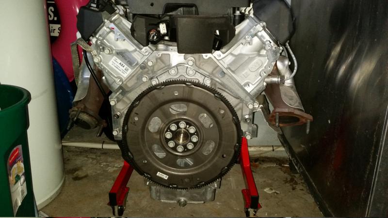
So I just acquired a Gen V engine for a project. I am at the start of building a new house so progress will be slow for a while, but I got an excellent deal on this, so I couldn't pass it up. It's the new LV3 4.3 V6 LT1 engine out of a 2014 truck. Here it is, straight off the truck:
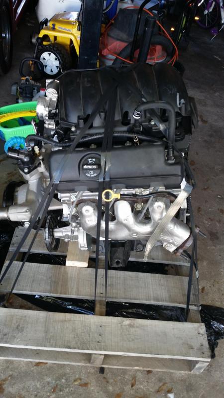
I am expecting an LS specific engine storage stand to arrive tomorrow so I haven't bothered to take it off the pallet yet, but I couldn't help myself so I removed the vacuum pump, motor mounts, and water pump. The engine mount bosses on the block look very similar spacing wise to the one on my LS2 block, except there are only 4 bolt bosses per side instead of 6.
Here it is semi-naked:
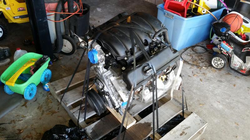
The new waterpump design and general belt routing is a hot mess for what I want to do with the engine, so I took it off for an exploratory look. At first glance, the design of the water pump passages and bolt pattern look similar to the Gen 3 and 4. I am looking at two options. I am either going to make or buy AN adapters and run a rail mount electric pump like a Meziere, or I am going to see if I can adapt the Gen IV waterpump, and make a top mount for the alternator. If anyone in the Tampa, Florida area has one they are not using for an afternoon so that I can mock it up, and verify that it will bolt up to the block, I would gladly leave a deposit while I used it. Hit me up via PM if you can help.
I also have a Gen 3/4 aftermarket Corvette Balancer laying around from a previous project. If the Gen 3/4 waterpump works out, I will have a keyway broached in to this spare balancer (Gen V comes with a metric width key on the snout), and try it out. I want to make this motor as compact as possible, and the Gen V truck balancer sticks out pretty far. It has 3 separate belt surfaces. One for the AC, one for the water pump, and one for the vacuum pump.
As a quick side note, I removed the vacuum pump, and there are two threaded holes that needed to be plugged. One goes directly to the main oil gallery, and the other is a return the pan. They are both M12 course thread, so either a flange bolt with a silicone washer or an M12 allen head cap screw and some teflon will suffice.
The oil pan is pretty deep on this engine. I will have to see how this is going to work out. I have not seen a picture of the inside of an LV3 oil pan, but I have seen the corvette pan, and it appears that the sump tube is cast in to the pan. That might present some challenges. I have a very talented welder/fabricator at my disposal, so I know I can make it happen, if I have to.
As far as my plans for the engine, I plan to tackle this in stages.
Stage 1, get the engine running, get the car built around it and shake it down.
Stage 2. Remove the DOD by replacing the DOD lifters, plugging the stands, that go to the solenoids.
Stage 3. Call Comp, and see if they will grind me a cam, or regrind the stock one. While I am in there, I would put the phase limiter in there. At that time, I would probably change all the rocker arm bearings out for the captured style, and put a good set of valve springs on it.
Stage 4. (Way down the road). Port the heads. Maybe find a shop that already has a good LT1 program and see if it will work on these heads. Also Intake port job. At first glance the Throttle body flange isn't going to allow for adapting a larger TB, as is. I might have to get creative down the road.
Stage V. This is way,way down the road, but If I can find another engine, or long block, I would like to look at a wet sleeve setup, and offset grind the stock crank for Quad 4 bearings. Some quick maths show 5.1 liters or 310 cubic inches.
So if anyone needs any measurements let me know. I also want to give a great big shout out to Greg@PacePerformance. This engine did not come with a computer or harness, and had a couple of sensors that were damaged. Greg has been able to track all these parts down for me, as well as flash the base truck OS on the new computer, and provide me with pin out information at a more than reasonable price. I can't recommend him enough, if you need something for a project, check him out.
Also in case anyone is wondering what this is going in, I'll give you a hint. It will go BEHIND this:

Last edited by 96 Comp T/A; Oct 18, 2014 at 10:54 AM.
I can shed some light on the water pump info...
The bolt spacing is close enough so that a Gen 5 water pump will bolt to the Gen 3/4 engine.
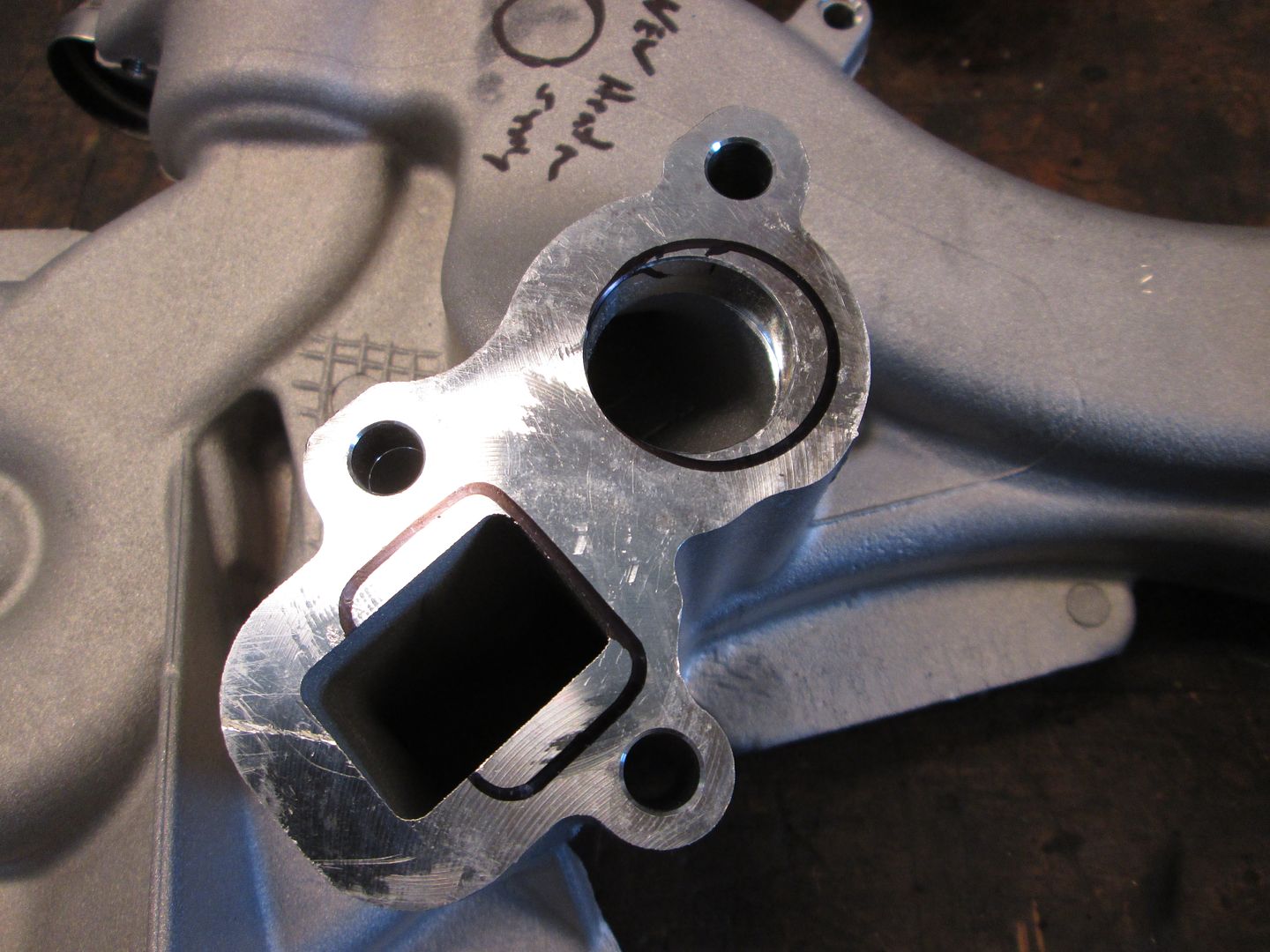
The issue is the coolant port shapes are different. Here is a picture of a Gen 5 pump with the Gen 3/4 gasket openings marked with a sharpie:

Whatever pump or fittings you attach to a Gen 5 block might need the ports or external housing built up some to get a good seal or use a thin plate and appropriate gaskets on both sides. Either way there are possibilities to accomplish what you are looking to do.
The bolt spacing is close enough so that a Gen 5 water pump will bolt to the Gen 3/4 engine.
The issue is the coolant port shapes are different. Here is a picture of a Gen 5 pump with the Gen 3/4 gasket openings marked with a sharpie:
Whatever pump or fittings you attach to a Gen 5 block might need the ports or external housing built up some to get a good seal or use a thin plate and appropriate gaskets on both sides. Either way there are possibilities to accomplish what you are looking to do.
I can shed some light on the water pump info...
The bolt spacing is close enough so that a Gen 5 water pump will bolt to the Gen 3/4 engine.
The issue is the coolant port shapes are different. Here is a picture of a Gen 5 pump with the Gen 3/4 gasket openings marked with a sharpie:
Whatever pump or fittings you attach to a Gen 5 block might need the ports or external housing built up some to get a good seal or use a thin plate and appropriate gaskets on both sides. Either way there are possibilities to accomplish what you are looking to do.
Thanks!
To be honest, I am leaning more towards the remote setup. It would be of great value to me to be able to run two smaller radiators rather than a big single in my application. I am extremely airflow challenged for the radiator with the engine mounted in the back of the car. Mounting a single radiator up high obstructs rearward vision, and the shape of the buggy isn't necessarily ideal from an airflow perspective because with a windshield in the car there is a low pressure area and it pulls through the radiator backward in to the passenger compartment. With split radiators, I can get creative with the ducting.
Cool project. It is amazing at the power boost that the Gen V engines have over the Gen IV. The V6 makes more power than the older 5.3L engines. The new 5.3L is rated at 355hp! wow...
Need pictures of the car!
Andrew
Need pictures of the car!
Andrew
So bad news on the motor mount front. While the mounts on the V6 indeed look very similar to an LS1, they are not. They are about a 1/4 off in every direction. Thankfully, my engine came with both engine mounts, which are 2 piece, and I have salvaged the piece of steel that bolts to the block. I will be retrofitting my storage stand with these tomorrow. Pictures in the AM.
Well the car doesn't exist just yet. We have started to mock up the suspension geometry in Autocad, but I am probably a year away from starting on the frame.
Trending Topics
LS1 Tech Stories
The Best V8 Stories One Small Block at Time

Top 10 Greatest Cadillac V Series Performance Models Ever, Ranked
Pouria Savadkouei
Top 10 Most Powerful Chevy Trucks Ever Made!

Hennessey's New Supercharged Silverado ZR2 Has 700 HP
Verdad Gallardo
Coachbuilt N2A Anteros Is an LS2-Powered C6 Corvette In Italian Clothes
Verdad Gallardo
Awesome K5 Blazer Restomod Comes With C7 Corvette Power
Verdad Gallardo
10 Camaros You Should Never Buy

10 LS Engine Myths That Refuse to Die
Verdad Gallardo
Five Reasons the Camaro Was the Most Pivotal Player in the Pony Car Wars 2.0
Brett Foote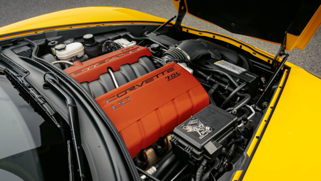
10 Reasons the LS7 Is GM's Most Extreme Naturally Aspirated V8 Engine Ever
Verdad Gallardo So regarding the mounting pattern, here is a shot showing the LS1 stand, with the LV3 mount laid over top of it:
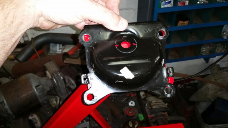
The upper right bolt hole is aligned, the remainder are not. So I simply modified the stand and welded on the LV3 mount on top of it.
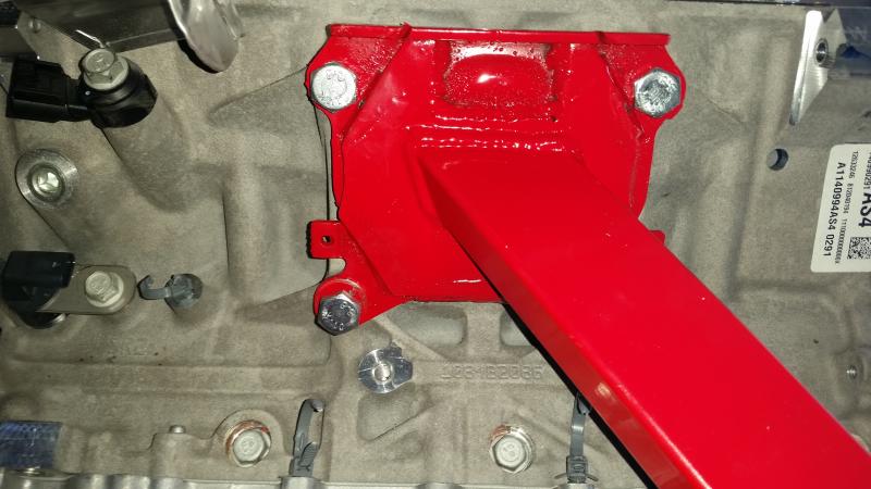
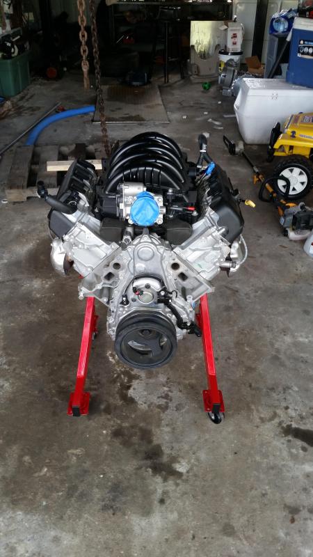
Finally, here it is standing on it's own four feet.

The upper right bolt hole is aligned, the remainder are not. So I simply modified the stand and welded on the LV3 mount on top of it.

Finally, here it is standing on it's own four feet.


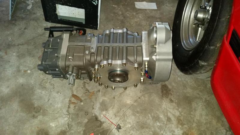
Well the crankshaft is the 8 bolt pattern, common to the LSA and LSX 454 engines (maybe a couple more engines too, so a known quantity). Bellhousing pattern is almost identical, except for one bolt at the peak, so any SBC/LSx tranny bellhousing will bolt up. You will only use 5 of the 6 bolts. There are tons of options from mild to wild as far as clutches go. Since the car will hopefully be less than 2300 lbs. I don't need dual disc or anything aggressive, so it's just a matter of getting a proper flywheel, and then a standard Camaro application for a pressure plate.

That's the pic I was looking for.
My understanding was that ALL the truck Gen V motors had VVT/DOD and automatic trans. I was curious if there was a manual trans flywheel capability, spacing for trans, starter compatibility issues.
I'm guessing with your build, you be using an adapter with flywheel/clutch/starter compatibility already worked out.
I measured the diameter of the hole in the back of the crank for the pilot bearing to be 1.706 inches (give or take a .001), which is 43.33mm, which matches up with the LS7 bearing diameter, per a google search.
That's the pic I was looking for.
My understanding was that ALL the truck Gen V motors had VVT/DOD and automatic trans. I was curious if there was a manual trans flywheel capability, spacing for trans, starter compatibility issues.
I'm guessing with your build, you be using an adapter with flywheel/clutch/starter compatibility already worked out.
My understanding was that ALL the truck Gen V motors had VVT/DOD and automatic trans. I was curious if there was a manual trans flywheel capability, spacing for trans, starter compatibility issues.
I'm guessing with your build, you be using an adapter with flywheel/clutch/starter compatibility already worked out.
The transaxle I have has an option (albeit expensive) for a bolt on LS bellhousing, that allows the use of standard GM style clutch components. My other option is to use a VW style 9" flywheel + dual disk clutch with an adapter plate, and a VW style starter. I already have a new GM style mini starter, so I will probably ante up for the bellhousing, but it's a wash cost wise. The GM style clutch is relatively new to the scene but results have been positive.
Thanks for the confirmation on the pilot bearing. It's good to see that GM didn't decide to save 2 cents and had the cranks machined, which probably means that these cranks will be used in cars/trucks with manual transmissions at some point.
Andrew
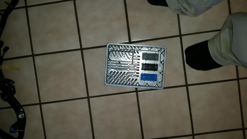
So a little progress. I received the Harness and ECM from Greg @ Pace, along with a few missing sensors and oil cooler block-off. I can usually clean up and redo a harness in about 4-6 hours taking my time but this one is going to take considerably longer, it looks like. It's tough to tell in this picture but there are probably 30-40 individual connectors on this harness.
I bought the de-pinning tools so that I can remove them non-destructively in case of any issues.
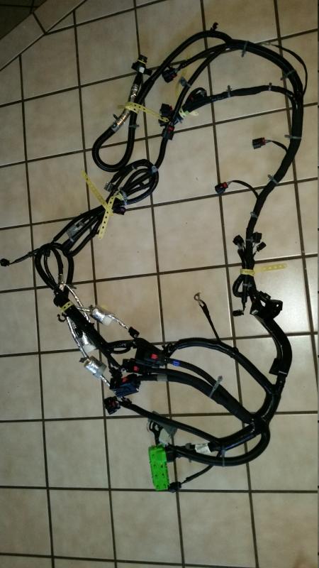
I bought the de-pinning tools so that I can remove them non-destructively in case of any issues.


Step 1. Remove all this #@$#@#$ convoluted tubing and electrical tape.
Step 2. Plug in all the plugs to the engine and mark so you at least know where most of the plugs terminate.
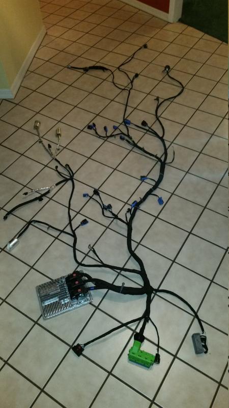
Step 3. De-sheath the entire harness and start removing unneeded circuits, such as TCM, tranny connectors. Secondary O2 sensors, EVAP, DOD, etc. This is what I will be doing for the next few nights. I was hoping to not buy the paper Helms Manual, but I might need it after all.


