When you click on links to various merchants on this site and make a purchase, this can result in this site earning a commission. Affiliate programs and affiliations include, but are not limited to, the eBay Partner Network.
sorry if this isn't the right spot for this question.
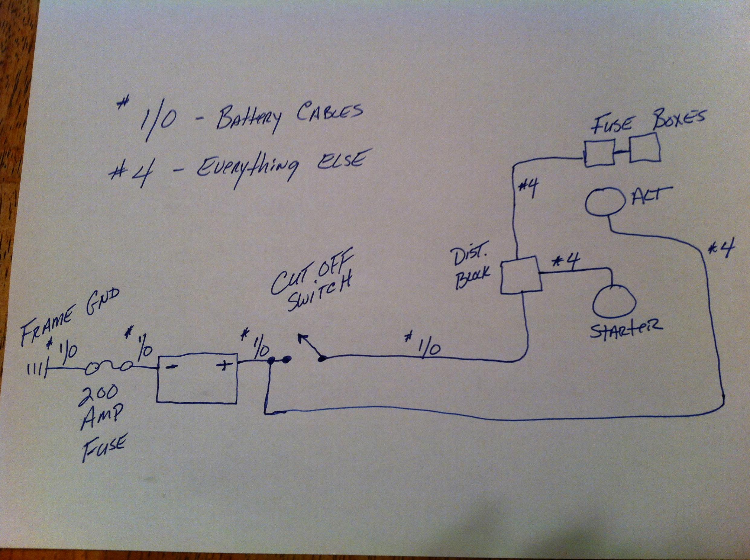
i'm trying to plan out all the items i need to install under my car (brake lines, fuel lines, battery cables, etc...) and have some questions regarding moving the battery to the hatch. i'm installing an LQ4 engine in a 1984 Trans Am and will be using '99 f-body accessories and PCM / wiring. i know i need a shut off switch and sealed box. i found the diagram below on here for wiring the battery in the hatch. here are my questions:
i have read that some alternators have an exciter wire that should get connected to a dash light? how can i tell if this is this something i have to wire on my swap? i'm planning on installing all autometer gauges so if this wire is required, where should i run it to?
should i be concerned with cutting power to the PCM with the battery shut off switch? is there a way to keep power to the PCM to not loose the stored information or is everything in the PCM read only?
sorry if these questions are basic / stupid. building the engine was easy, but i'm having a hard time understanding all the wiring involved in the swap.
Your F-body alternator should have a single wire connector that is tied to the PCM and nothing more is needed for it besides your main hot/charging cable.
Is the cut-off for racing applications to kill everything or to simply disconnect the battery for storage? If it's just for a battery disconnect you can get away with tieing your alternator #4 charging cable to the distribution block
I noticed in the diagram the frame is used as the common ground. Highly recommend running a ground wire (same size as power) to the starter mounting bolt with a jumper to the frame and body.
I noticed in the diagram the frame is used as the common ground. Highly recommend running a ground wire (same size as power) to the starter mounting bolt with a jumper to the frame and body.
Your F-body alternator should have a single wire connector that is tied to the PCM and nothing more is needed for it besides your main hot/charging cable.
Is the cut-off for racing applications to kill everything or to simply disconnect the battery for storage? If it's just for a battery disconnect you can get away with tieing your alternator #4 charging cable to the distribution block
the car is being built for the street, but i would like to take it to the track a couple times eventually. i started looking into all this because i want to move the battery and then figured if i'm relocating it i might as well do it right and install a sealed box and shut off switch.
Originally Posted by 33willys
I noticed in the diagram the frame is used as the common ground. Highly recommend running a ground wire (same size as power) to the starter mounting bolt with a jumper to the frame and body.
thanks for the insight. since this is a unibody car, can i just install one ground from the starter to the front frame rail or do i also need another lead to the firewall / strut tower?
FWIW you can get some nice cabling off later model BMWS they have right rear trunk mounted batteries in the E46(2000-2006) and others.. My 2005 has a MONSTER battery in the rear because of all the post shutdown crap it does when you turn the car off, it literally takes 20 minutes for the car to totally shut down.. Note, They also have a pyrotechnic battery disconnect on the battery , feed it a few volts and it pops the + circuit.. They cost a lot from the dealer..
My battery's been trunk mounted for 17 years now - no problems. As long as the ground in the back is sound (CHECK IT!) and the engine to block ground is sound (CHECK IT!) there's no need to run a ground to the front. And, doing so can cause stray currents from ground loops. Assure your grounds are sound....don't run the additional loop. There's enough metal in the body that if your ground connections are sound, grounding the block/heads/starter to the chassis in the front is just like connecting them to the battery. If you don't know what ground loops are -- google/wiki....
On your schematic -- I'd let the big cable to the starter be stand alone, and connect your fuse boxes to the alternator output. When you energize the starter, the car starts and then you de-energize it, you get big voltage spikes/valleys for a brief period of time (think of a bungee jump -- jumper bouncing up/down after the jump). Wired up as you are showing, I've had the voltage swings when the starter drops out be big enough to drop below the 9V threshold to maintain stereo presets and clock on my unit -- requiring me to reset the head unit every time I started the car. Separated the starter 12V+ from the rest of the 12V+ power users and all that went away. If you decide to follow this approach, be sure the #4 gauge running to alt is enough to power everything but the starter. Just a thought.
Here's a crappy schematic of what I did after considerable research. Wire gauges are noted as 8 and 1/0 on the runs. Use welding cable for the 1/0 runs - it is less expensive, and the copper strands are smaller diameter so it's more flexible and carries more current than the automotive stuff.
Here is how mine is done. Yes, some of it might be overkill, but I never have electrical issues, or ground issues.
I used all 2/0 welding lead for my battery runs. Some people will say it's overkill to run the ground cable all of the way to the front. I don't like using the chassis of the car to transfer my ground. You CAN NOT have too many grounds, and I don't have any problems with the way I run mine.
Positive 2/0:
- Battery to disconnect switch
- Switch along pass side (inside) to pass through connection at firewall
- Other side of connection on firewall to starter. Newer gear reduction starter
- Other side of connection at firewall to power post behind driver's side strut tower. Smaller wire, 4-gauge. Car is wire tucked. This is where all of my accessories, fusible links etc connect.
Negative 2/0:
- Battery to bolt that pass through floorboard of trunk
- Other side of bolt (under car) to quad shock mount bolt hole
- Back on top side of bolt (in the trunk) all the way to front sway bar mount.
- Front sway bar mount to engine block
- Front sway bar mount to bolt that passes through behind drivers strut tower. For all of the harness and accessory grounds.
3G alternator:
- 4-gauge from alternator the 150 amp mega fuse mounted on side of battery box
- 4-gauge from mega fuse to battery side of disconnect switch
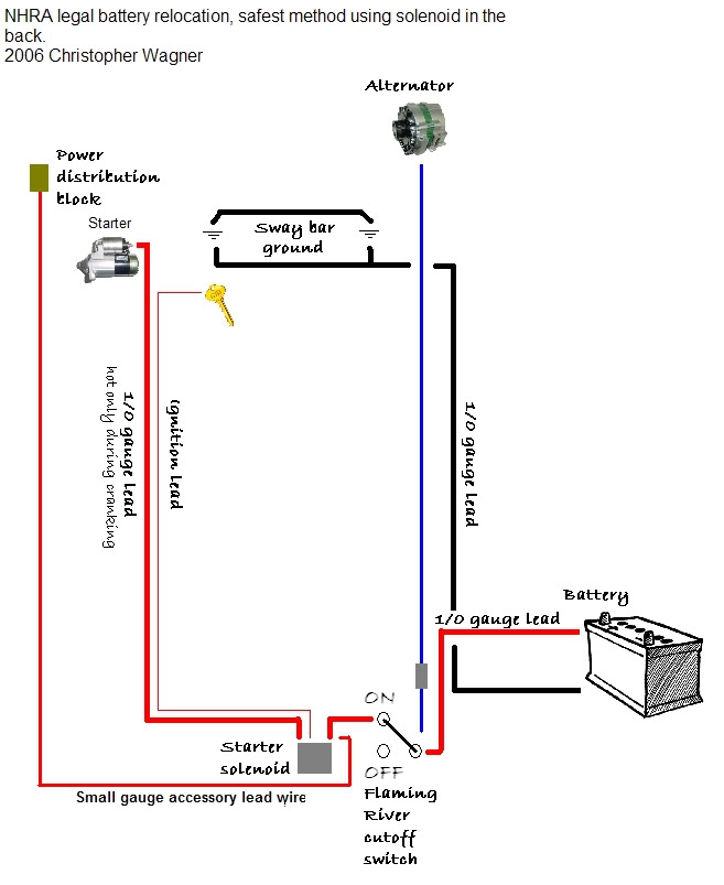
The wire that comes from the alternator to the battery needs to be on the battery side of the disconnect switch. Which yours is, I just wanted to mention that. It needs to be separated from the main power feed for the car (switched side of disconnect switch). There are certain situations where the alternator could continue to power the car after the switch is disconnected if they were both on the switched side.
For the original poster:
I'm not sure why you have the big fuse on your ground cable coming off of the battery. It needs to be on the feed coming from the alternator.
So I believe your diagram is correct, with the exception of the fuse on the ground. Also, like I said, I prefer running a ground cable the same size as the power cable all the way to the front, but there are lots of people that do it like you did with success. And that's a topic that will be discussed/argued forever lol.
I'm not sure why you have the big fuse on your ground cable coming off of the battery. It needs to be on the feed coming from the alternator.
Where you have a fuse on your schematic - you're only protecting the line from the alternator to the battery. When you put the fuse between the ground and the battery (provided you simply make the chassis your ground at the battery location) you protect all hot wires big enough to carry enough current to pop the fuse. So, your 2/0 from battery to starter is completely unprotected. Bad news - if that shorts to ground (think car accident), you'll likely burn the car down. Good news - won't have to go far to find a fireman.
Where you have a fuse on your schematic - you're only protecting the line from the alternator to the battery. When you put the fuse between the ground and the battery (provided you simply make the chassis your ground at the battery location) you protect all hot wires big enough to carry enough current to pop the fuse. So, your 2/0 from battery to starter is completely unprotected. Bad news - if that shorts to ground (think car accident), you'll likely burn the car down. Good news - won't have to go far to find a fireman.
Never seen it done that way I'll have to look into it, thanks for the info.
On a side note, my fuse between my alternator and battery saved me when I had a regulator go bad on an alternator and it was putting out 32 volts! Popped that fuse and it kept it from getting my battery.


 06-21-2017 | 05:59 AM