


Vacuum / PCV diagram?

Thread Starter
Launching!
Joined: Jul 2016
Posts: 286
Likes: 6
I'm wondering if anyone has a link, diagram or picture that shows how the vacuum/PCV subsystem on my 6.2L from 2008 should be connected. I've done some searching, but I've found a good bit of conflicting information & data that might be useful if it wasn't for the pictures being absent thanks to photobucket... 
For anyone else who might be searching on the same topic, I've found that this page seems to be helpful with understanding how the system is supposed to work, but the images are hijacked as mentioned above, which somewhat limits it's usefulness.
And here's another (Nissan-flavored) page on the topic that I'm working through.
Both of the above examples seem to have decent information, & I'll probably be able to figure out how to hook everything up once I get through them, but I'd really rather have known-good, application-specific data to work from.
Thanks in advance, I appreciate any help.
think of the crankcase as a cup. It holds oil in the bottom of the cup. the top of the cup is the valve cover. There are 2 "tops" on your cup, 2 valve covers.
One valve cover allows air into the crank case. If you care about the engine, this side should feed from after an air filter. Or install an air filter of your own here.
The other valve cover is where air is leaving the crankcase to get into the intake manifold. this is where the pcv valve goes. pcv valve is just a "check valve" it only allows flow one direction. You want it to flow INTO The intake manifold when there is vacuum in the intake.
there is more we can with the PCV than just the above, but this is the simplest shortest answer until you ask more specific questions.
Pics of my Gen IV LS3 (6.2L) crate engine run by '08 Corvette ecu.
The engine allows 'make-up' air INTO the engine from the hose that runs between the air inlet pipe and the valve cover fitting. My finger points to the clamp where that hose connects to the valve cover inlet fitting. Note -- 1) that valve cover inlet nipple has an orifice in it that limits how much air can enter; 2) the supply point for that make up air is DOWNSTREAM of the mass air sensor so that the make up air is metered.
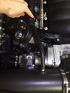
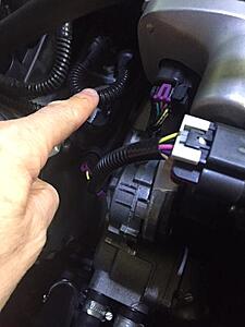
The PCV connection occurs through the little loop of tubing shown in the picture. One end connects to the intake just behind the throttle body, and the other to the lifter valley below the intake. You can see the DBW throttle body motor on the right side of the picture. So metered make up air enters the crankcase through the orifice in the valve cover and leaves through the lifter valley pulling crankcase contaminants into the intake manifold to be used in the combustion process.
The engine allows 'make-up' air INTO the engine from the hose that runs between the air inlet pipe and the valve cover fitting. My finger points to the clamp where that hose connects to the valve cover inlet fitting. Note -- 1) that valve cover inlet nipple has an orifice in it that limits how much air can enter; 2) the supply point for that make up air is DOWNSTREAM of the mass air sensor so that the make up air is metered.

The PCV connection occurs through the little loop of tubing shown in the picture. One end connects to the intake just behind the throttle body, and the other to the lifter valley below the intake. You can see the DBW throttle body motor on the right side of the picture. So metered make up air enters the crankcase through the orifice in the valve cover and leaves through the lifter valley pulling crankcase contaminants into the intake manifold to be used in the combustion process.

Trending Topics
LS1 Tech Stories
The Best V8 Stories One Small Block at Time

6 Common C5 Corvette Failures and What's Involved In Repairing Them
Pouria Savadkouei
Retro Modern Bandit Pontiac Trans AM Comes With Burt Reynolds' Autograph
Verdad Gallardo
Top 10 Greatest Cadillac V Series Performance Models Ever, Ranked
Pouria Savadkouei
Top 10 Most Powerful Chevy Trucks Ever Made!

Hennessey's New Supercharged Silverado ZR2 Has 700 HP
Verdad Gallardo
Coachbuilt N2A Anteros Is an LS2-Powered C6 Corvette In Italian Clothes
Verdad Gallardo
Awesome K5 Blazer Restomod Comes With C7 Corvette Power
Verdad Gallardo
10 Camaros You Should Never Buy

10 LS Engine Myths That Refuse to Die
Verdad Gallardo Thread Starter
Launching!
Joined: Jul 2016
Posts: 286
Likes: 6
Pics of my Gen IV LS3 (6.2L) crate engine run by '08 Corvette ecu.
The engine allows 'make-up' air INTO the engine from the hose that runs between the air inlet pipe and the valve cover fitting. My finger points to the clamp where that hose connects to the valve cover inlet fitting. Note -- 1) that valve cover inlet nipple has an orifice in it that limits how much air can enter; 2) the supply point for that make up air is DOWNSTREAM of the mass air sensor so that the make up air is metered.

The PCV connection occurs through the little loop of tubing shown in the picture. One end connects to the intake just behind the throttle body, and the other to the lifter valley below the intake. You can see the DBW throttle body motor on the right side of the picture. So metered make up air enters the crankcase through the orifice in the valve cover and leaves through the lifter valley pulling crankcase contaminants into the intake manifold to be used in the combustion process.

The engine allows 'make-up' air INTO the engine from the hose that runs between the air inlet pipe and the valve cover fitting. My finger points to the clamp where that hose connects to the valve cover inlet fitting. Note -- 1) that valve cover inlet nipple has an orifice in it that limits how much air can enter; 2) the supply point for that make up air is DOWNSTREAM of the mass air sensor so that the make up air is metered.
The PCV connection occurs through the little loop of tubing shown in the picture. One end connects to the intake just behind the throttle body, and the other to the lifter valley below the intake. You can see the DBW throttle body motor on the right side of the picture. So metered make up air enters the crankcase through the orifice in the valve cover and leaves through the lifter valley pulling crankcase contaminants into the intake manifold to be used in the combustion process.


Thread Starter
Launching!
Joined: Jul 2016
Posts: 286
Likes: 6
think of the crankcase as a cup. It holds oil in the bottom of the cup. the top of the cup is the valve cover. There are 2 "tops" on your cup, 2 valve covers.
One valve cover allows air into the crank case. If you care about the engine, this side should feed from after an air filter. Or install an air filter of your own here.
The other valve cover is where air is leaving the crankcase to get into the intake manifold. this is where the pcv valve goes. pcv valve is just a "check valve" it only allows flow one direction. You want it to flow INTO The intake manifold when there is vacuum in the intake.
there is more we can with the PCV than just the above, but this is the simplest shortest answer until you ask more specific questions.
One valve cover allows air into the crank case. If you care about the engine, this side should feed from after an air filter. Or install an air filter of your own here.
The other valve cover is where air is leaving the crankcase to get into the intake manifold. this is where the pcv valve goes. pcv valve is just a "check valve" it only allows flow one direction. You want it to flow INTO The intake manifold when there is vacuum in the intake.
there is more we can with the PCV than just the above, but this is the simplest shortest answer until you ask more specific questions.
Great info, thank you kingtal0n. I'm sure I'll have a few more questions shortly, when I'm actually hooking the vacuum/PCV system together - but thank you for taking the time/effort! I would add - on most applications, the old school PCV valve is not only a check valve but also a flow restrictor limiting the 'vacuum leak' that could occur when connecting vacuum to the crankcase when a make up air source is present. The check valve function stemmed from days past when gasoline laden vapors downstream of the carb (the vacuum source) could have made their way into the crankcase. Anyone who's ever witnessed a crankcase explosion knows why that's a bad idea -- hence the PCV/check valve
This thread has a bunch of extra info about pcv routing (crankcase pressure and oil control systems) and the purpose of a can
http://www.nsxprime.com/forum/showth...=1#post1909293
http://www.nsxprime.com/forum/showth...=1#post1909293


Michael Yount has it right for the OE gen IV system. To elaborate, the tube coming from the air intake tube to the valve cover is the "clean side" because it normally feeds clean filtered air into the engine. The short u-loop tube from the valley cover to the intake is the "dirty side" because it is sucking contaminated, oil-filled air from the engine into the intake manifold. Even though the lifter valley has baffles and a flow-limiting restrictor, oil will still find it's way through that system and into the intake manifold, so if you want to install a catch can / oil separator you would splice it into the loop between the valley cover and the intake.
It's critical that all the air going through the PCV system is "metered air". It has to be metered because it flows from the clean side, through the engine, and to the dirty side and INTO the combustion chamber. If it's not metered, you will not get enough fuel to cover that air and it will cause the engine to run lean. Therefore the "clean air" inlet should take air AFTER the mass air flow meter to make sure that air is accounted for in the fuel mixture.
It's critical that all the air going through the PCV system is "metered air". It has to be metered because it flows from the clean side, through the engine, and to the dirty side and INTO the combustion chamber. If it's not metered, you will not get enough fuel to cover that air and it will cause the engine to run lean. Therefore the "clean air" inlet should take air AFTER the mass air flow meter to make sure that air is accounted for in the fuel mixture.
The O2s will help adjust, but they are narrow band and only work when the engine goes into closed loop. So if you don't meter the PCV air, you may have some issues at cold start and overall performance will suffer.
Agree -- and I'll add, OEM's moved to HEGO's several decades ago to speed up the movement to closed loop....out of necessity as the cold start/open loop time is by far the dirtiest part of the emissions cycle. As regs tightened the numbers, they had to clean up cold starts. As a result, most starts/most climates, cars rarely spend more than 20-30 seconds in open loop before switching to closed. Even a cold start in a cold climate rarely results in more than 60-90 seconds before the sensors are warm enough to move to closed loop. As mentioned before - for a variety of reasons, a big vacuum leak, unmetered combustion air and a mass air/map sensor mismatch on amount of air entering the engine are likely to set off a check engine light and error codes.
Easy to avoid as laid out by a number of us above.
Easy to avoid as laid out by a number of us above.
most performance setups don't use closed loop, or not traditional closed loop.
For example I have wideband analog output set for (15.2:1 @ 0.005v, 14.8:1 @ 0.995v)
And there are no narrowbands on the engine.
No point keeping a bunch of narrowbands around unless you have luxury space and don't mind looking at them. In other words, I wouldn't mind having a couple narrowbands for the sake of cylinder balance (one on the right, one on the left, is nice) so you can compare the 4 injectors to the other 4 injectors in theory.
But the wideband, if reading properly, is like having infinite narrowbands, one for each a/f possible