When you click on links to various merchants on this site and make a purchase, this can result in this site earning a commission. Affiliate programs and affiliations include, but are not limited to, the eBay Partner Network.
I'm fairly certain I was on the correct pin, the grey wire. On the GTO, the Duty Cycle Signal (grey wire) goes to pin F on alternator and Gen On Signal (org wire) goes to pin L on the alternator.
When I put my scope on the grey wire, it's a 250Hz signal, not the 128 I expected. I tried both freqs on the signal generator and no change. I even tried 500Hz that is supposedly used on certain SIlverados. I've tried both 12v and 5 v. The clutch seemed fine by hand but I welded the pulley just in case, no change.
I did notice that your drawing shows the PWM signal going to the L terminal on the alternator.
The L terminal is the one that controls the alternator. That's the one you need to be controlling. The F terminal is a PWM output from the alternator and an input to the ECM to let the ECM know if the engine has enough RPM to support the desired output voltage.
The L terminal is the one that controls the alternator. That's the one you need to be controlling. The F terminal is a PWM output from the alternator and an input to the ECM to let the ECM know if the engine has enough RPM to support the desired output voltage.
Ok, so I went out and played with the orange wire that's supposedly (I'm not taking anything for granted at this point) on the L terminal of the alternator. I put in spade connectors on both wires to try and make testing easier. So...
Engine running, when I tap into the orange wire with the spade terminals connected, I get no reading (couple hundred mV) but the alternator is charging, albeit a little low (13.7-8 Vdc).
I disconnect the orange wire, alternator stops charging. Place the scope lead on each disconnected end of the orange wire, no signal or voltage.
I set my generator up at 128Hz and 35%. I attach the scope up to verify output: 12Vdc, 128Hz, 35%DC.
I started the engine, and touched the generator lead to the alternator end of the orange wire (should be the L terminal) and voltage drops to 1-2 volts on the scope and no charging is taking place. Remove the generator signal and reattach the orange wire from the PCM, starts charging, but still low. Headlights, A/C, stereo (with aftermarket amps) has no affect on voltage.
I just want to say Thanks for the Info. I have a 07 Trailblazer with the 2 pin alternator and I've been looking for a way to control my voltage. I run a pretty big audio system so this will be a big help if I am able to get it to work. Thanks again!!
I just want to say Thanks for the Info. I have a 07 Trailblazer with the 2 pin alternator and I've been looking for a way to control my voltage. I run a pretty big audio system so this will be a big help if I am able to get it to work. Thanks again!!
YW. So assuming your current charging system is working and you want an occasional override, are you going to put a switch in there to flip form normal charging to override charging?
YW. So assuming your current charging system is working and you want an occasional override, are you going to put a switch in there to flip form normal charging to override charging?
I haven't gave it much thought yet. I'm looking into switching to a lithium battery setup maybe. And I know you gotta watch your charging voltage with them. A switch is a good idea. I'll probably use a switch & relay to switch back and forth as needed.
I don't think so. The 2006+ alternator has it's own table probably somewhat similar to the one you posted internally. It does what you're trying to do on it's own. All you need to do is tell it what voltage you want (and give it enough RPM) and it does all this compensation for you.
I would think that your table should not have battery volts in it at all. I predict that if you do, the car's voltage will be unstable since both the Holley and the alternator are going to try to regulate the voltage and constantly fight each other. Instead, the table might be RPM only. Anything under 400 RPM, you'd want to alternator to not load the engine down and anything over 400 RPM you command the alternator to put out the desired voltage..
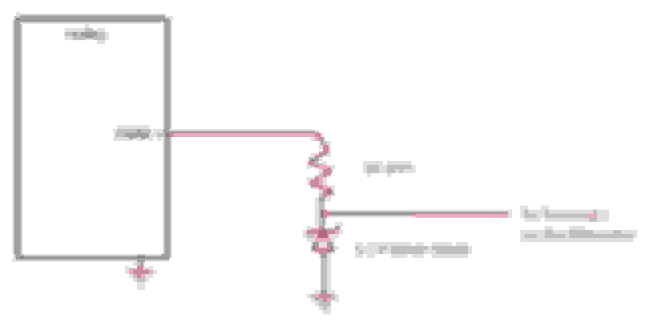
Remember that for Holley PWM+ and PWM- duty required is opposite.
So let's say you want 14.37 volts above 400 RPM and you are using the PWM- .........Then try 85% across the board under 400 RPM and 30% across the board over 400 RPM and this wiring:
For PWM- these are the command percentages. Find your desired voltage and set that percent over 400 RPM
90% = 11.0 V
80% = 11.56 V
70% = 12.12 V
60% = 12.68 V
50% = 13.25 V
40% = 13.81 V
30% = 14.37 V
20% = 14.94 V
10% = 15.5 V
So let's say you want 14.37 volts above 400 RPM and you are using the PWM+ ......... Then try 15% across the board under 400 RPM and 70% across the board over 400 RPM and this wiring:
For PWM+ these are the command percentages. Find your desired voltage and set that percent over 400 RPM
10% = 11.0 V
20% = 11.56 V
30% = 12.12 V
40% = 12.68 V
50% = 13.25 V
60% = 13.81 V
70% = 14.37 V
80% = 14.94 V
90% = 15.5 V
Let's say you're going to the track and want higher voltage so your ignition and fuel pump have some extra juice. Then you might have a table RPM on one axis and some switch input on the other so you could flip the switch on your dash and command the alternator to put out the higher track voltage.
Once again, I don't have a Holley, so I can't test this.
If i give it a 70.4% Duty Cycle I should get 14.4 based on the measured values you recorded (guessing this approximate based on load, but a good starting point).
I'm doing this on a vette alternator and I have the S term I figured it would be more fun to do this instead of adding a battery wire to the socket. From what i read (if right) I wouldn't really need to run F & L, since the internal regulation would take over? Am I reading that right?
I thought about running +PWM as there are a lot more outputs for the Dominator, but the zener isn't in stock @ my house and no one is open today to get one.
I figured RPM, VS Map and then I can scale for idle and kick the alternator up for AC Blower fan, etc...
So the picture is a good start if running MAP/RPM shouldn't be an issue.
I should also stipulate that I've got the wires in place because I'm switching the car over from the E-38 to the Dominator and cut the pin ends off and re terminated with the BP-Automotive harness I already had in place.
If i give it a 70.4% Duty Cycle I should get 14.4 based on the measured values you recorded (guessing this approximate based on load, but a good starting point).
I didn't record these voltages. The duty table is from other sources.
Originally Posted by gixxer92
From what i read (if right) I wouldn't really need to run F & L, since the internal regulation would take over? Am I reading that right?
If you don't connect anything to the terminals you should get about 13.7 volts.
Originally Posted by gixxer92
I figured RPM, VS Map and then I can scale for idle and kick the alternator up for AC Blower fan, etc...
You don't need to kick this alternator up for A/C Blower fan etc. It does it on it's own. You might want to kick the engine RPM and cooling fan up for A/C. As long as the RPM is high enough, the alternator should output the voltage you asked for.
I didn't record these voltages. The duty table is from other sources.
If you don't connect anything to the terminals you should get about 13.7 volts.
You don't need to kick this alternator up for A/C Blower fan etc. It does it on it's own. You might want to kick the engine RPM and cooling fan up for A/C. As long as the RPM is high enough, the alternator should output the voltage you asked for.
I just swapped the regulator in my alternator from 4 pin to 2 pin, so now it's like a 2006 or newer alternator. Why??? Because GM thinks it's better than the older 4 pin one and they must know something.
Oh but everyone says you need a late model 2006+ ECM/BCM to run it or it only gives you 13.7 volts. Not necessarily.
.
Thank you for this. I specifically bought a DR44G because you can control it.
I couldn't find any information about how this alternator is controlled and this thread never came up in a search.
LSswap, thanks for sharing. I have have been a bit frustrated with my LS swap as the alternator has been "default" charging since we got it up and running. I am going to go Arduino nano. On the Corvette, did you end up tapping it into your fuse panel? As for the code, all I need to do, is copy and paste the code you shared? Thanks in advance.
LSswap, thanks for sharing. I have have been a bit frustrated with my LS swap as the alternator has been "default" charging since we got it up and running. I am going to go Arduino nano. On the Corvette, did you end up tapping it into your fuse panel? As for the code, all I need to do, is copy and paste the code you shared? Thanks in advance.
My Corvette has a non standard harness and fuse panel (understatement of the year). My transmission controller controls the alternator and all the other PWM stuff (6 fans, 2 fuel pumps).
I think I pasted an colored image of the code so it can be read more easily so not a direct cut and paste. But it's short, so should take a few minutes to duplicate.
All parts are ordered ! Thanks again, and I see what you mean about it being a pasted image. I am not sure what to do with the http://code.google.com/p/arduino-pwm...downloads/list piece yet, but I once I get the parts, I will try and work thru that piece. Thanks again for taking the time to share your knowledge. Getting this alternator is really the final piece for me.
Well crud... I don't know if it was temp related or something else, but my Arduino Nano burned out and the alternator defaulted back to 13.7V.
Hooked it up to the USB on my PC, and the thing got really hot, made an odd smell, and the PC stopped recognizing it.
So, I'm gonna give this a go since I can set the output voltage. I just hope it automatically boots up with 12V ignition signal and I dont have to turn it on every time.
Well the good news is that the PWM module I linked above works great. Set it up for 5V output, 128hz, and 67% duty cycle and the alternator is putting out 13.95V. Box boots right up with ignition, no delay.
Hooked up as follows:
Vin- to Ground
Vin+ to 12V switched ignition
PWM to alternator

 11-02-2019, 08:54 AM


 As far as I know the L terminal is a 5V PWM signal. Where did you see anything about 12V going to the L terminal?.