When you click on links to various merchants on this site and make a purchase, this can result in this site earning a commission. Affiliate programs and affiliations include, but are not limited to, the eBay Partner Network.
Awesome to hear that it�s compatible with the Holley. I�ve ran across threads before, but I haven�t done any actual reading on the PWM integration. I�m excited to read up on that.
Here is a video I made when I was getting it working on my Cougar.
Just read through this thread and it's a cool build with a cool story dude. Did you finish your intake setup yet? I'm getting things together to put an LQ9 with a TBSS intake in a 84 K5 and was planning on using the factory air cleaner box and same Airaid MIT but hadn't decided on how to mount it against the fender so it can pull in fresh cool air. Not sure if it'd be better to try to situate it to use the existing cutouts or place wherever's easiest and cut some new ones...
That�s actually something I�m going to be working on, hopefully this weekend. I�m going to snag an air box tray from the junkyard for a 07-13 truck, and figure out a way to make it fit. I might even remove the coolant bottle support if the newer style one will fit better. It doesn�t look complicated at all, probably just some trimming or a couple new holes to get it to bolt up.
I don�t think you�ll have a true cold air intake though, as the fender body doesn�t pull air from the front of the core support like the 88-98 trucks do. The core support really doesn�t have any decent size openings unless you wanted to fabricate or cut something to work.
I've had similar questions. It looks relatively easy to have a factory air box pull from the squarebody fender. But that doesn't do much good, since the squarebody fender will just be pulling engine compartment air from a little further back.
I wish there was an OEM air box of similar size that pulled air from the front face. That could be modified to pull directly through the core support. I haven't found such, though.
I think if you were dead set on doing a CAI style intake but keeping the OEM box, I would mount it similarly to what I’m doing, but remove the foam surround and fabricate a panel to cover the fender openings, fabricate a K&N style CAI shroud to separate the air box from the rest of the under hood components, then knock out the factory intake plate on the passenger side of the core support for an inlet. It wouldn’t exactly be for a high performance build, but if you were just dropping in a stock 5.3 like I did, it would probably be fine and also reduce your intake temps.
I think if you were dead set on doing a CAI style intake but keeping the OEM box, I would mount it similarly to what I�m doing, but remove the foam surround and fabricate a panel to cover the fender openings, fabricate a K&N style CAI shroud to separate the air box from the rest of the under hood components, then knock out the factory intake plate on the passenger side of the core support for an inlet. It wouldn�t exactly be for a high performance build, but if you were just dropping in a stock 5.3 like I did, it would probably be fine and also reduce your intake temps.
Somebody did exactly that on a build I saw a while back. They ran a pipe from the factory intake hole in the core support to the bottom of the donor's air filter box. Think they used 3" PVC for mockup and were going to use exhaust tubing for the finished install. Another option would be to pick up an ARB snorkel (like the 'burb in Dante's Peak) and put the donor air filter box wherever the snorkel comes through the fender and figure out a way to seal them to each other. I think that'd be coolest looking and best "cold air" option but it definitely wouldn't be a simple bolt on deal lol.
I hadn't thought of surrounding the whole box with a shroud. That could also work.
The thing is, from what I've been hearing, the OEM Silverado air filter assembly is second to none. Excellent flow and it sheds dirt well. It's supposedly a whole lot better than any K&N or similar aftermarket filter. I've wondered too, about just keeping the air box several inches back from the core support, and a couple inches away from the fender. Then rigging some plumbing to connect the air box to the core support. I'd be the most concerned about restrictive passages and a trashy appearance by doing this.
If it helps any, let me tell you what I did on my 04 Tahoe. I wanted a better air intake, so I got the Airaid intake tube, BUT not the cone filter. WHY? Because the stock airbox is more of a true cold air intake than the aftermarket ones. I did put a stock replacement AEM high flow panel filter in the airbox. Supposedly this combo dynos out better than a full aftermarket setup, too.
Once you get it running, some data may be your friend. Pic of mine below. Plenty of "outside air" enters the area in front of the air filter on mine. I've compared ambient temps with intake air temps reading through the diagnostic port. On a hot day sitting at idle for a bit (stop light for example) I might see intake air temps 10F higher than ambient. But most of the time - maybe 5F higher than ambient. I'm not gonna build a "box" to try and overcome that.
I don’t plan on doing anything for my truck, since that engine bay is pretty wide open, and air flow through the engine bay should be more than adequate, especially with the body lift and only being a stock-ish build. I’m assuming the vehicle you’re referring to is the Volvo? If so, that’s a pretty compact package with a lot less flow, and still works just fine like you said.
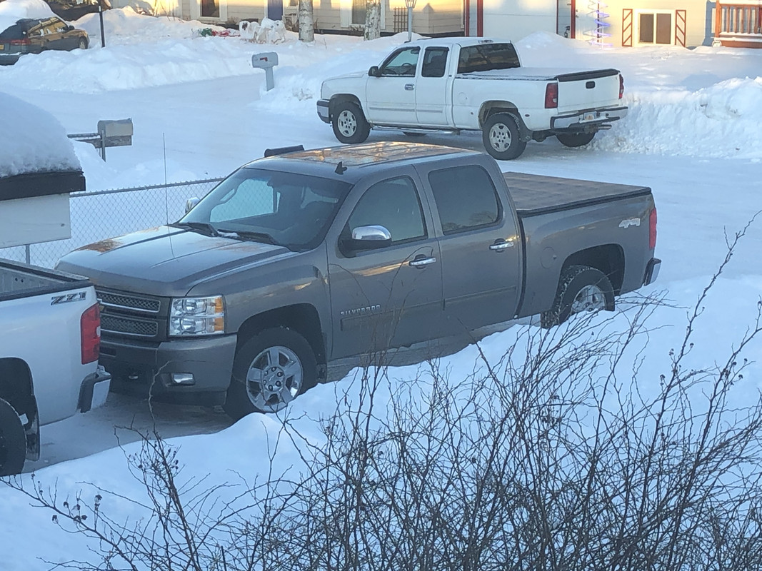
Alright, not a super big update this weekend as I had a few other major things going on. One, was picking up a new truck! 2012 Silverado LTZ, 1 owner, 106k miles for $5k under book.
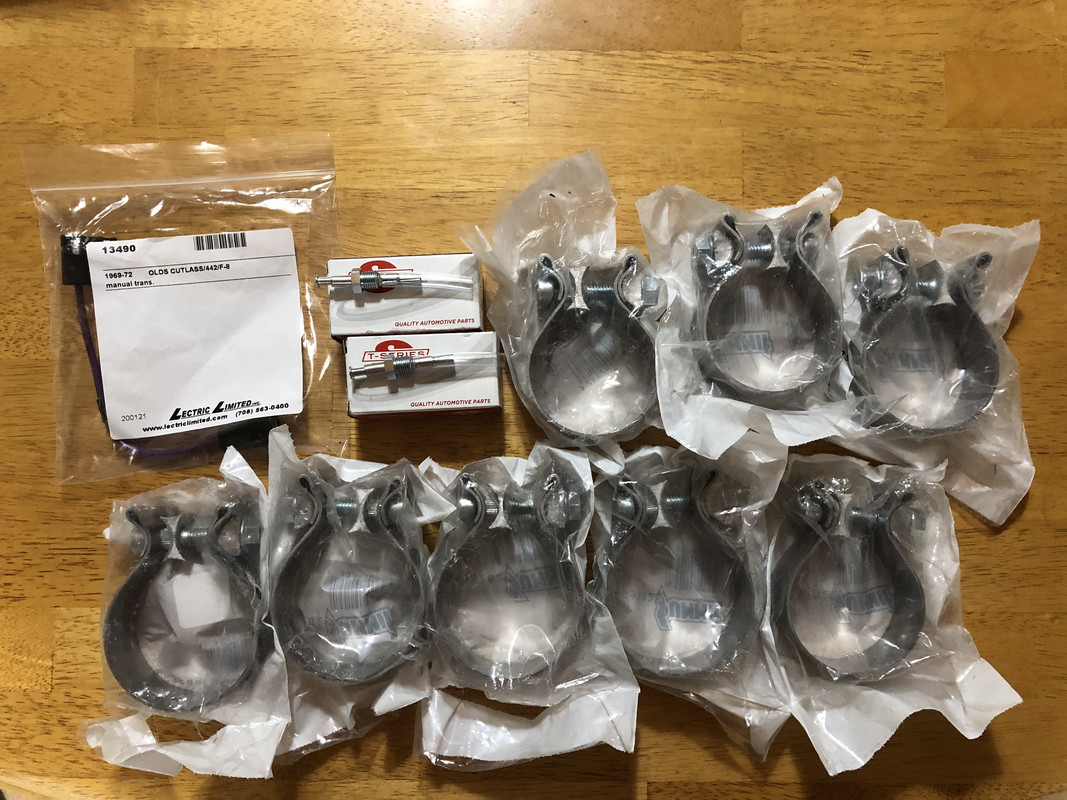
More parts! Exhaust clamps, door switches, and the wire for the starter switch.
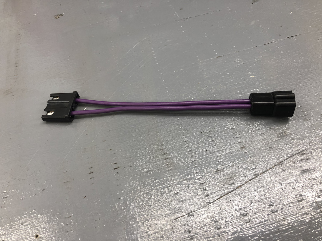
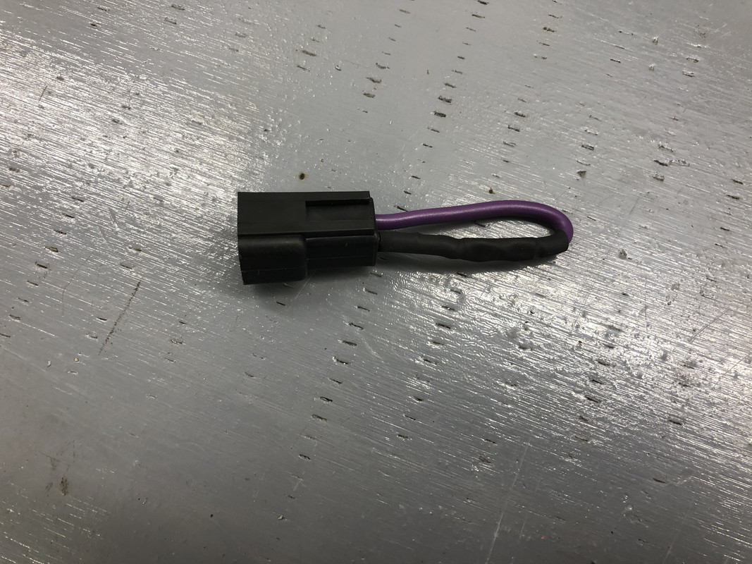
This is what I’m starting with to make the starter jumper.
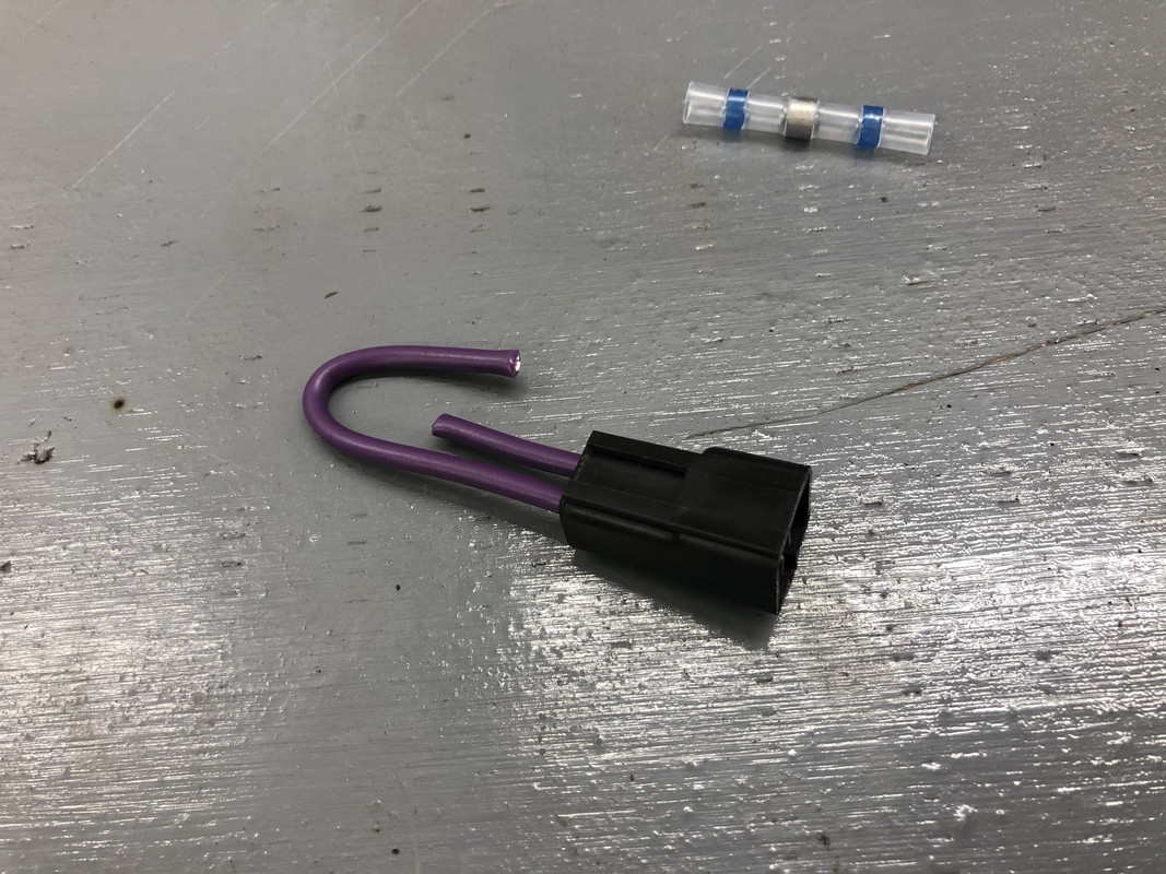
Cut down to a single plug.
Jumper made!
Door switches installed. These were the biggest pain in the *** to run the wires down to! 0/10 do not ever replace
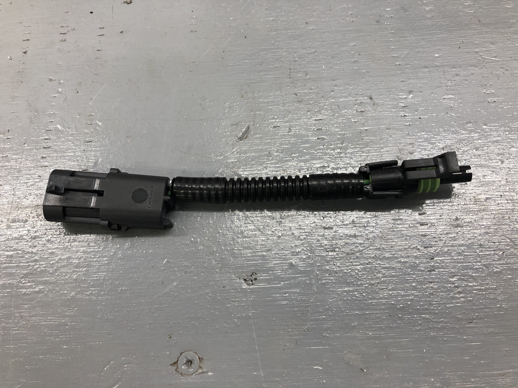
I also made part of the jumper that will supply the Holley harness with +12v switched from the ignition wire on the engine harness, and also disconnect the fuel pump wire.
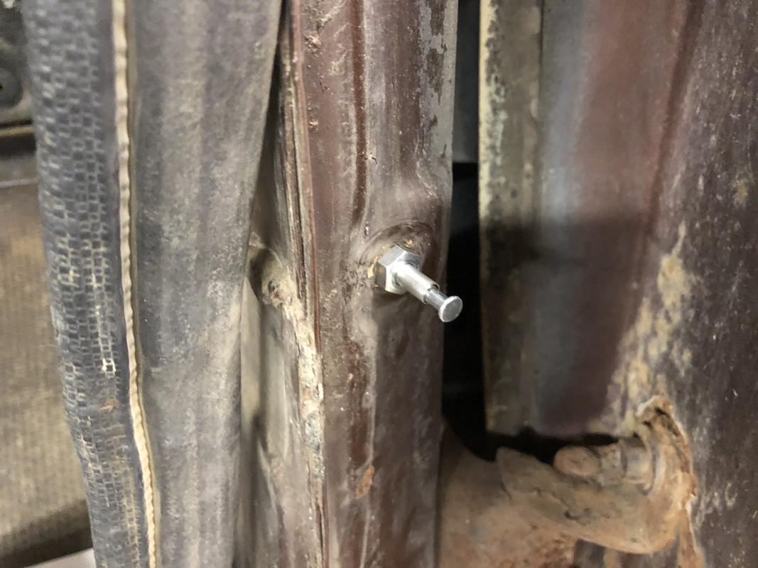
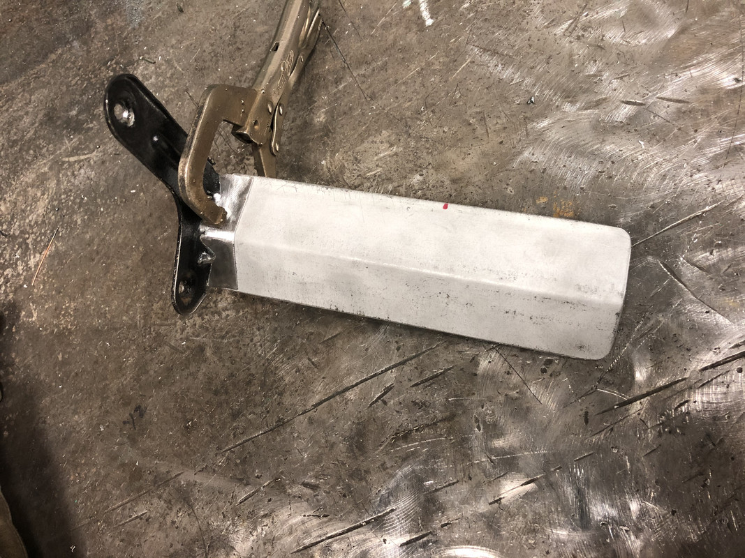
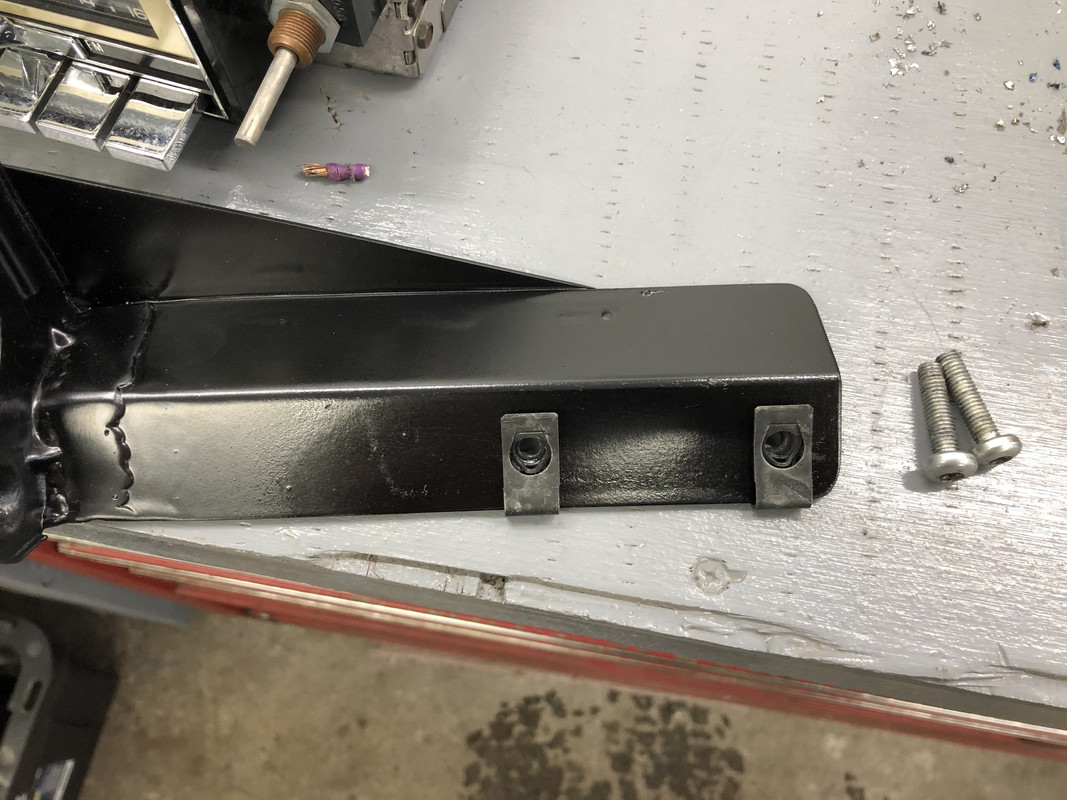
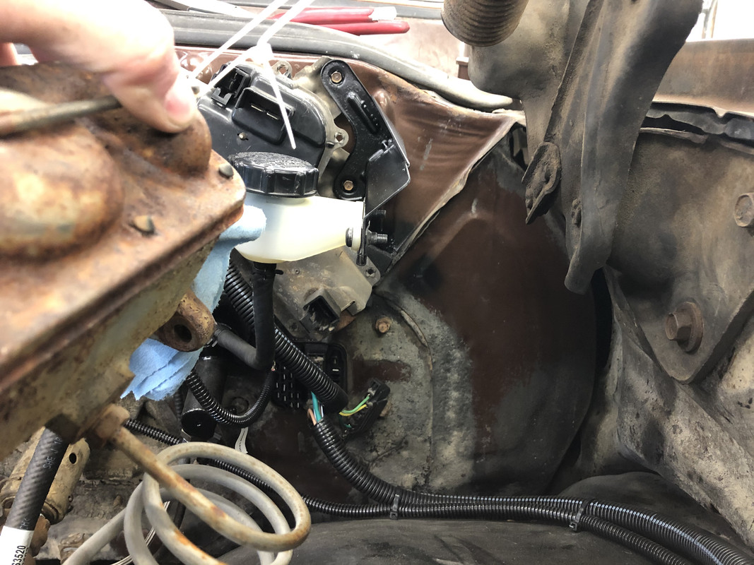
I started on the clutch reservoir bracket. It had to be mounted on the side due to the older style hood hinges interfering.
New mount bent up and fitted.
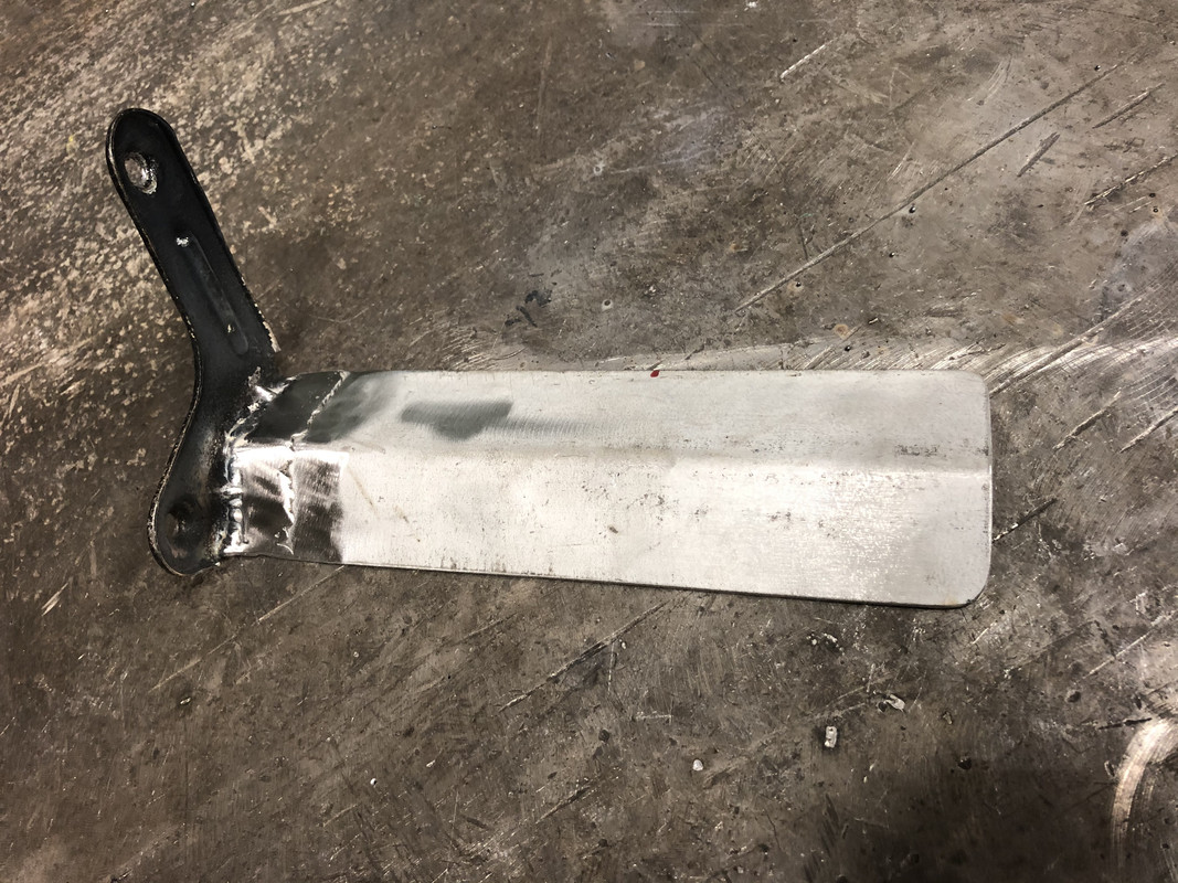
Added some side support to it.
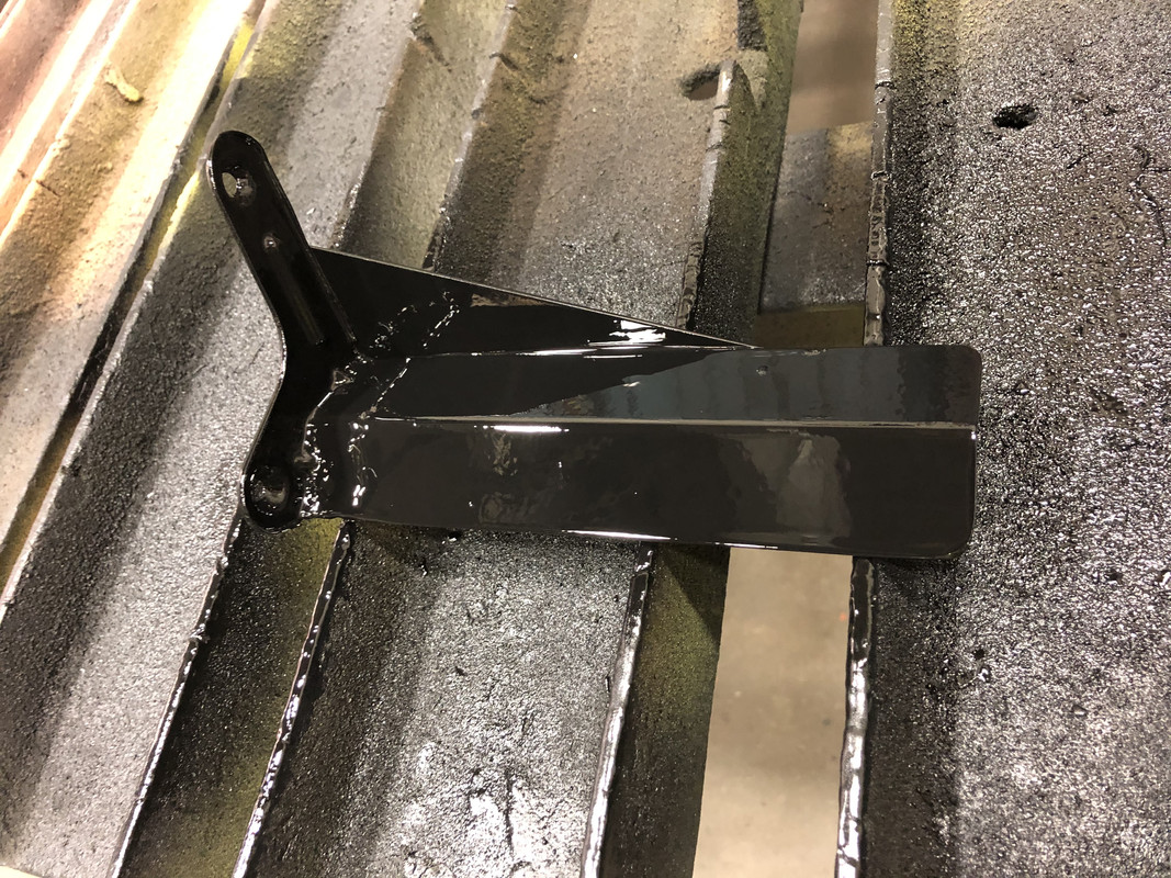
And painted!
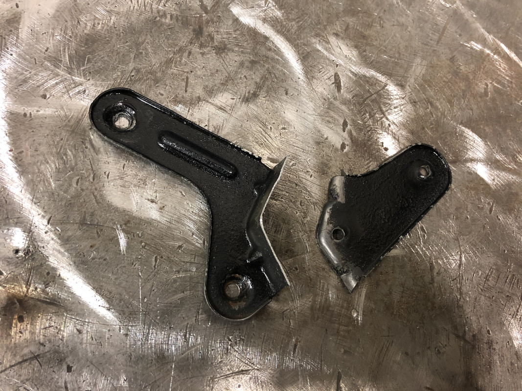
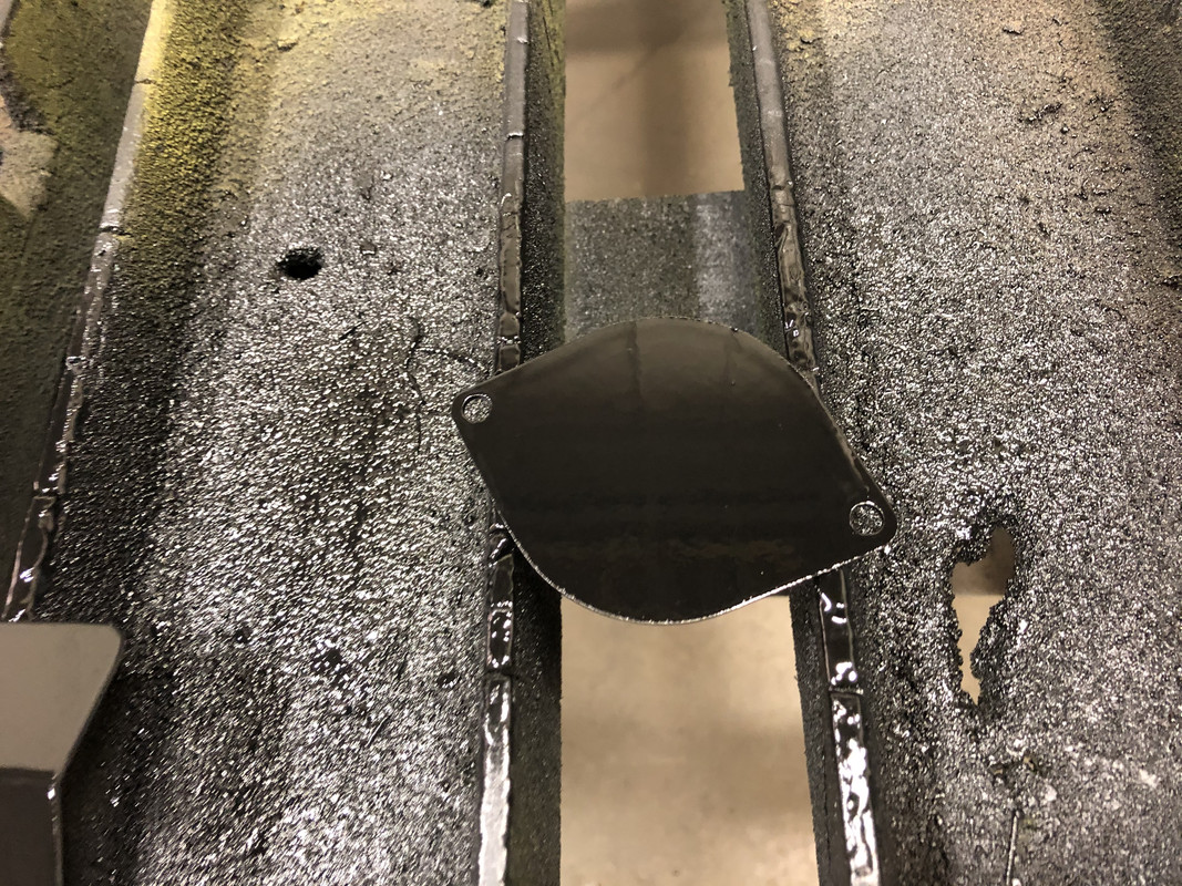
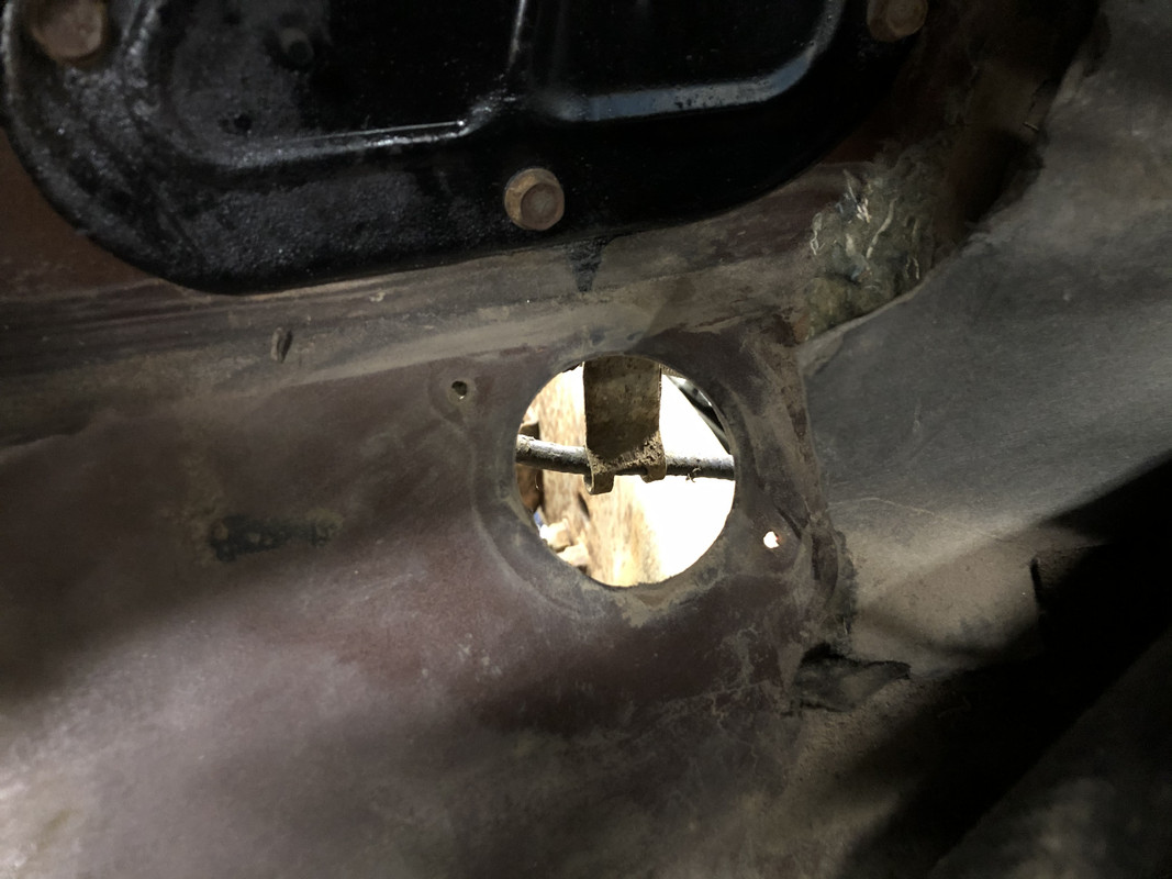
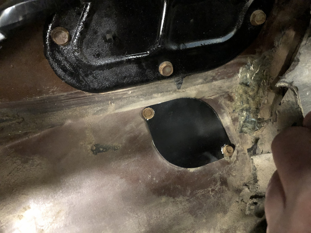
I also made a close off plate for the original clutch rod hole.
A little late but I ran across this setup on another forum today using the core support inlet tube for a cold air intake in case it gives you some ideas. Spectre inline air filter box with some 4" elbows and piping.
Interesting. That’s one way to do it also, although I’m not a fan of Spectre filters.
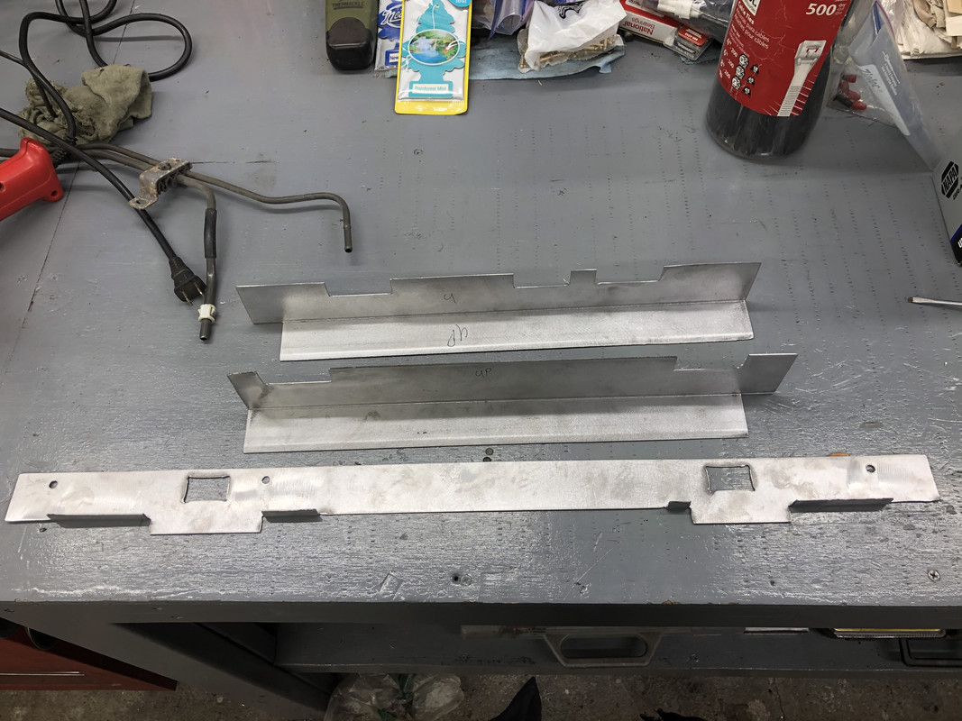
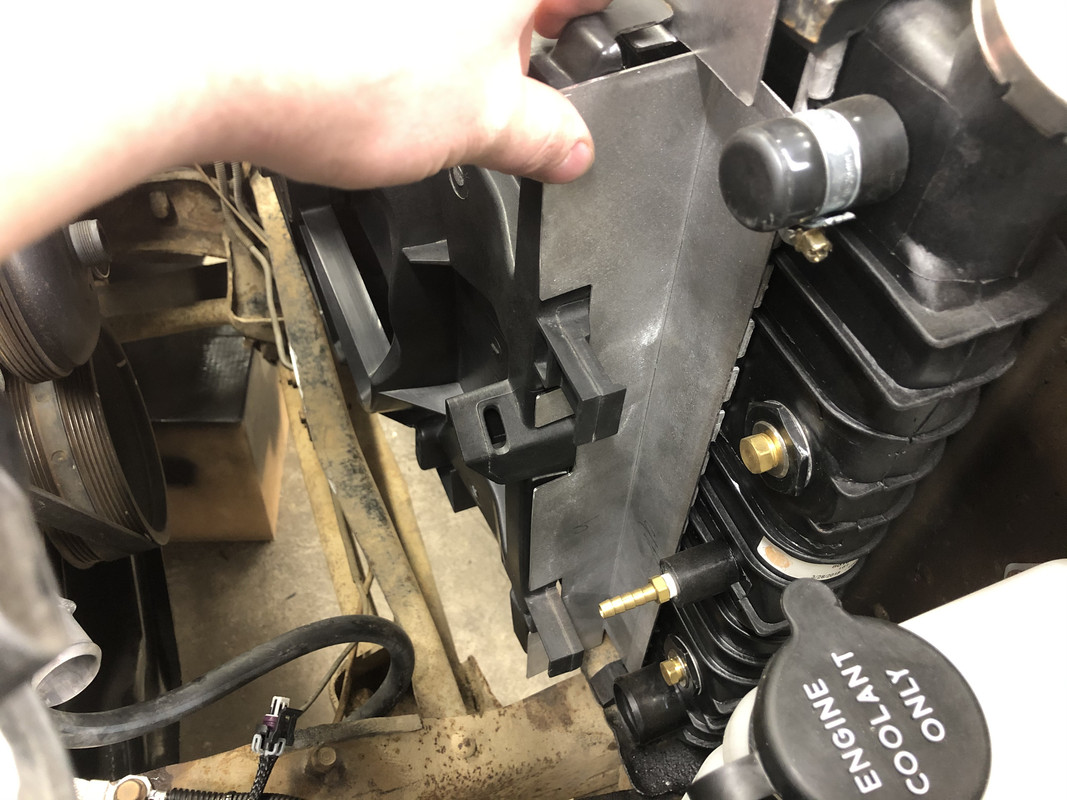
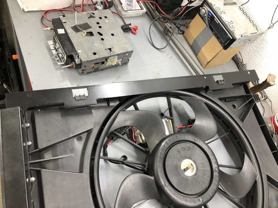
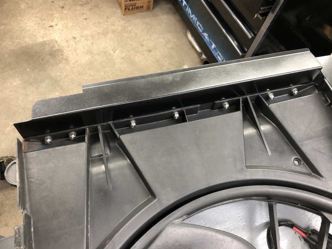
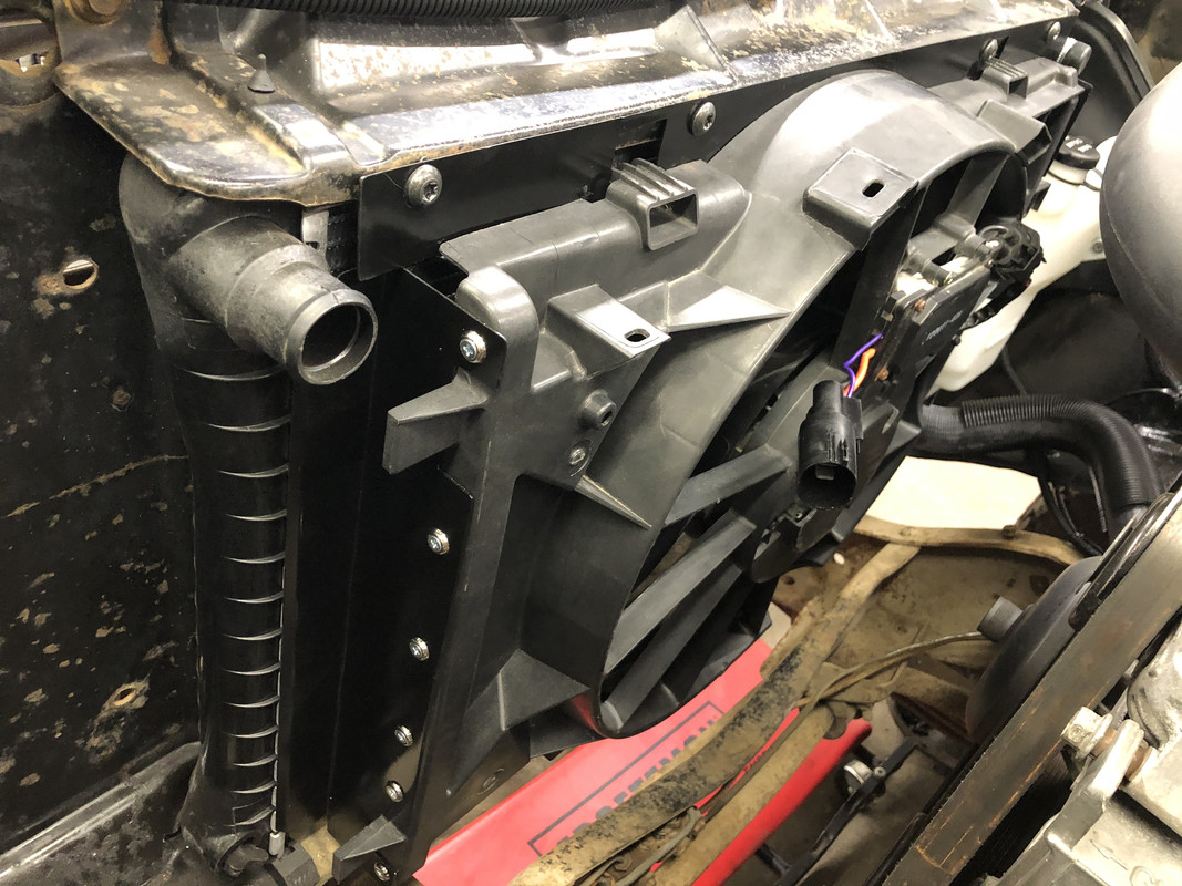
Anchorage Sheet Metal was able to quickly knock out my fan shroud covers, and they turned out great! After test fitting, I did end up trimming off 1/4” from the bottom on both sides, as well as radiusing the corners and adding a bit more clearance around the hose areas. Very happy with how they fit.
Test fitting each panel.
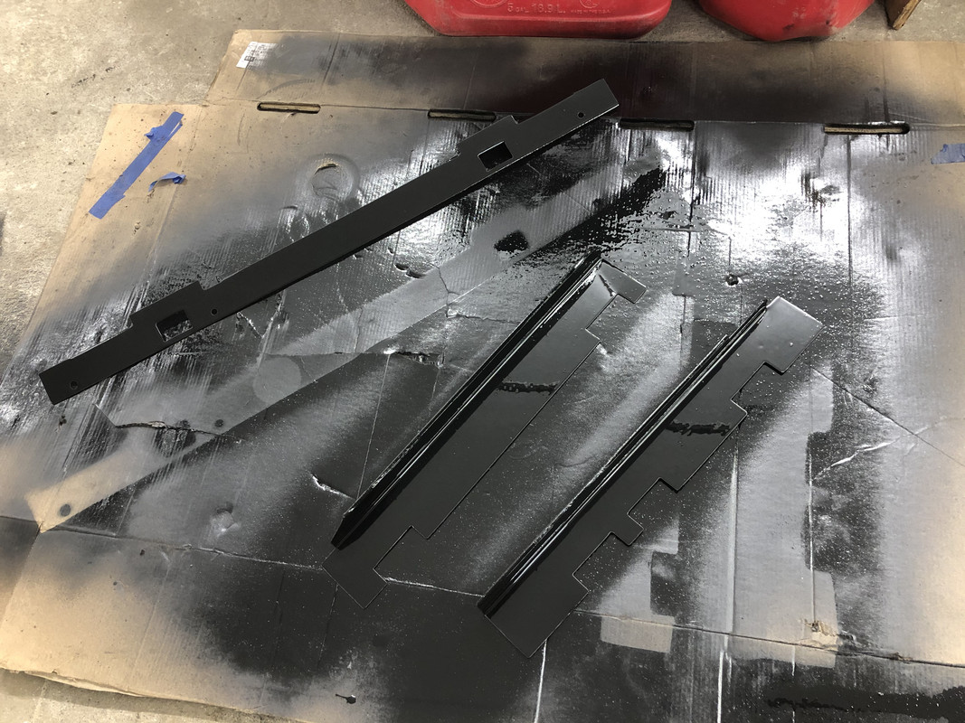
Now that I’m satisfied with the fit, let’s get some color on them!
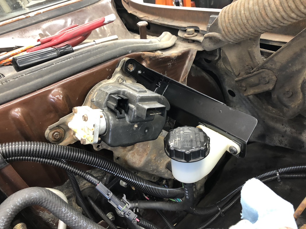
While the paint was drying, I worked on a few other projects. Transferred the bolt pattern of the clutch reservoir to the new bracket, and added some U-nuts.
Everything mounted up!
Now I have perfect clearance from the older style hood hinges!
This hole was also left over from the removal of the mechanical clutch rod.
I installed the cover I made with a bit of sealant, and it’s a perfect fit!
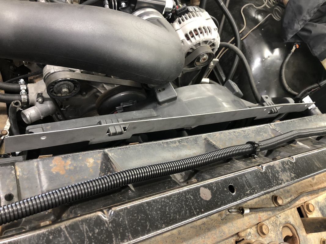
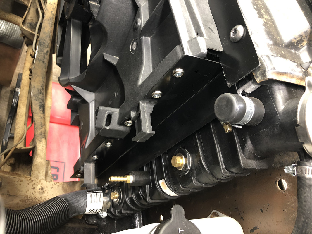
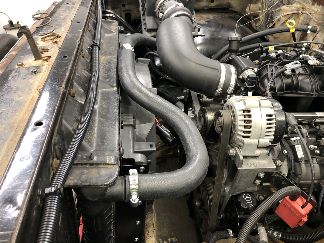
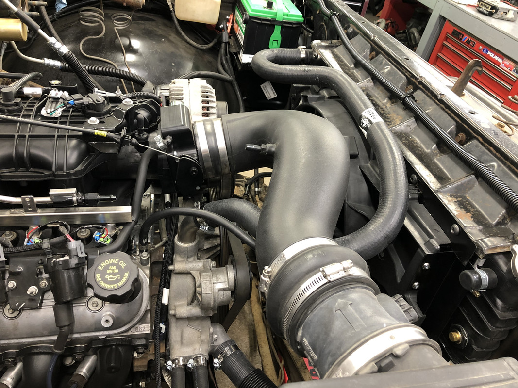
Now that the fan should be going in soon, the lower radiator hose was installed.
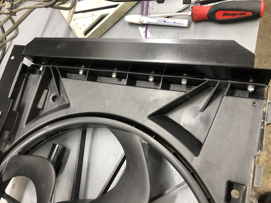
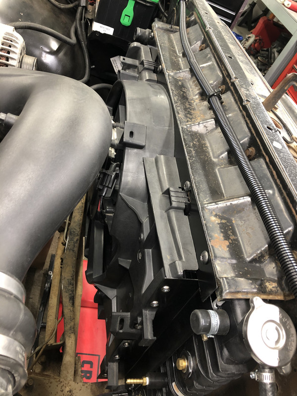
With the paint now dry, I installed the covers to the shroud.
Mounting complete!
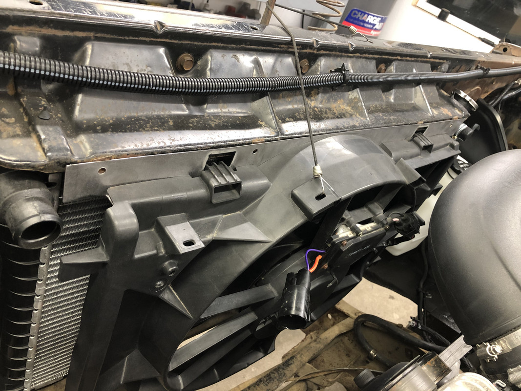
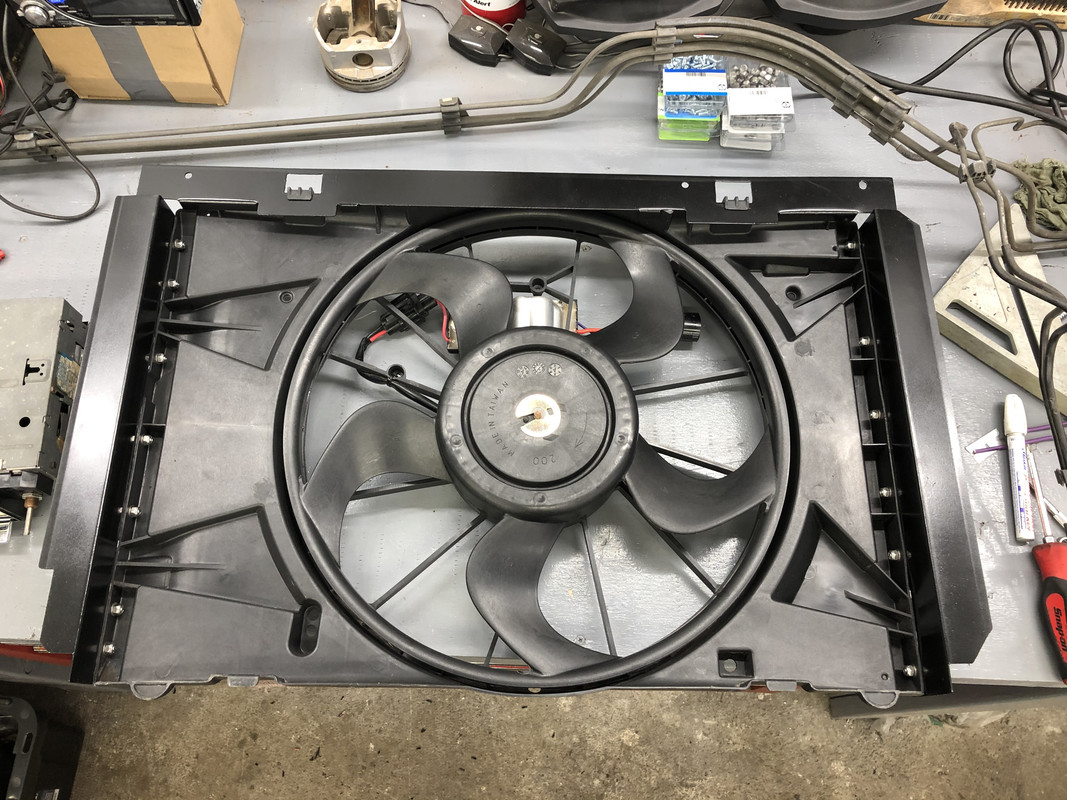
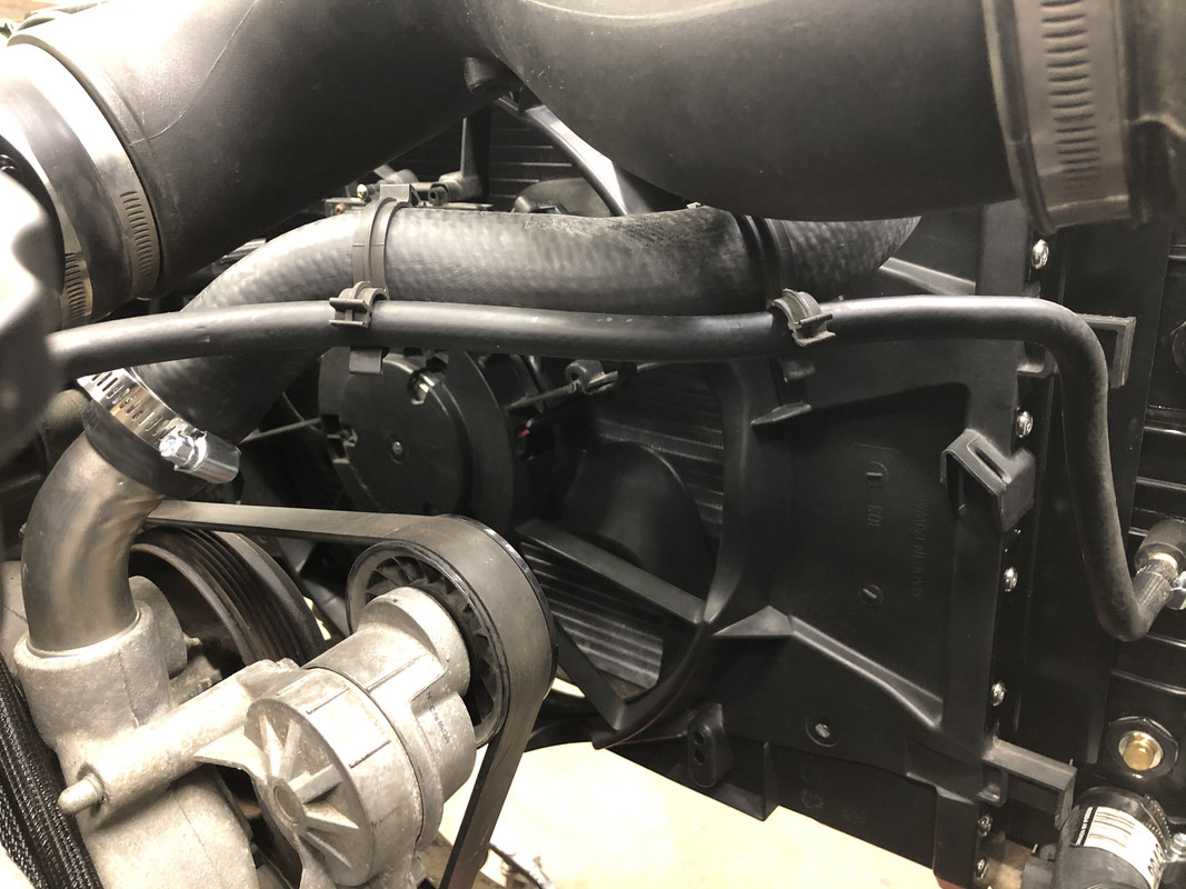
Dropped the fan into the core support.
Fully mounted!
Fitment at the bottom tabs.
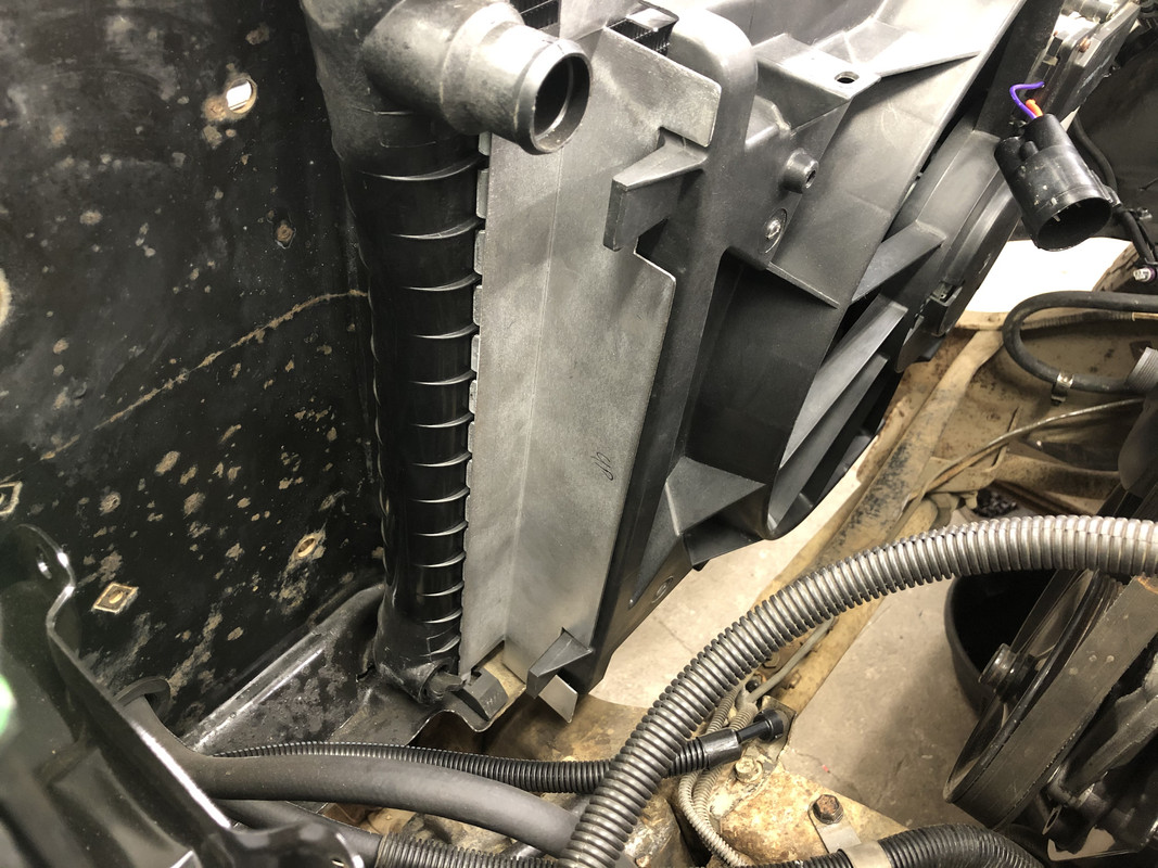
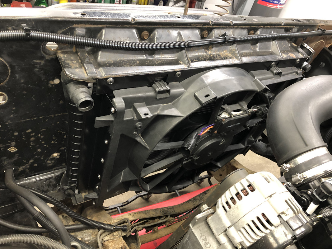
Upper radiator hose installed!
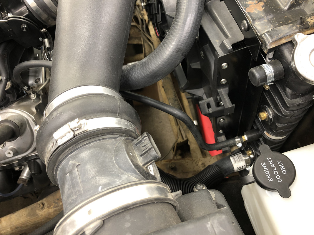
Steam hose installed.
One clip installed for the upper radiator hose, I still need to pick up another. This should also hold the Terminator X battery harness once that gets installed.
Not specifically, but from my research this fan uses the same controller as several other popular PWM fans. Unless I misunderstand how they work, all I’m doing is providing that controller with a power and ground source, and the PWM wire connects to the Terminator X and basically provides a signal for the controller to pulse the fan at different frequencies that either raise or lower the fan speed. If this controller is in fact the same, it should work just fine. At least that’s what I’m rolling the dice on, LOL.
Not specifically, but from my research this fan uses the same controller as several other popular PWM fans. Unless I misunderstand how they work, all I�m doing is providing that controller with a power and ground source, and the PWM wire connects to the Terminator X and basically provides a signal for the controller to pulse the fan at different frequencies that either raise or lower the fan speed. If this controller is in fact the same, it should work just fine. At least that�s what I�m rolling the dice on, LOL.
It is definitely a gamble. Have you been able to find the frequency and duty cycle numbers for that specific controller? It is definitely not the same as the Fusion/C6 box...although the connector is the same, but that doesn't mean anything.
Nothing yet for this one, but from what I’ve read, most people are finding OE controllers work well at 100 or 128hz, and between 15-90% duty cycle, although some have an inverted ramp rate. I’ll probably start there in the Holley, or even pick up a cheap PWM generator and manually see where this one likes to run at.


 02-04-2021, 12:31 PM