
1970 GTO Version 3.0
 01-21-2023, 10:06 PM
#621
TECH Senior Member
Thread Starter
iTrader: (7)

This morning I received the 1/2" hub centric wheel spacers that I ordered for the rear.
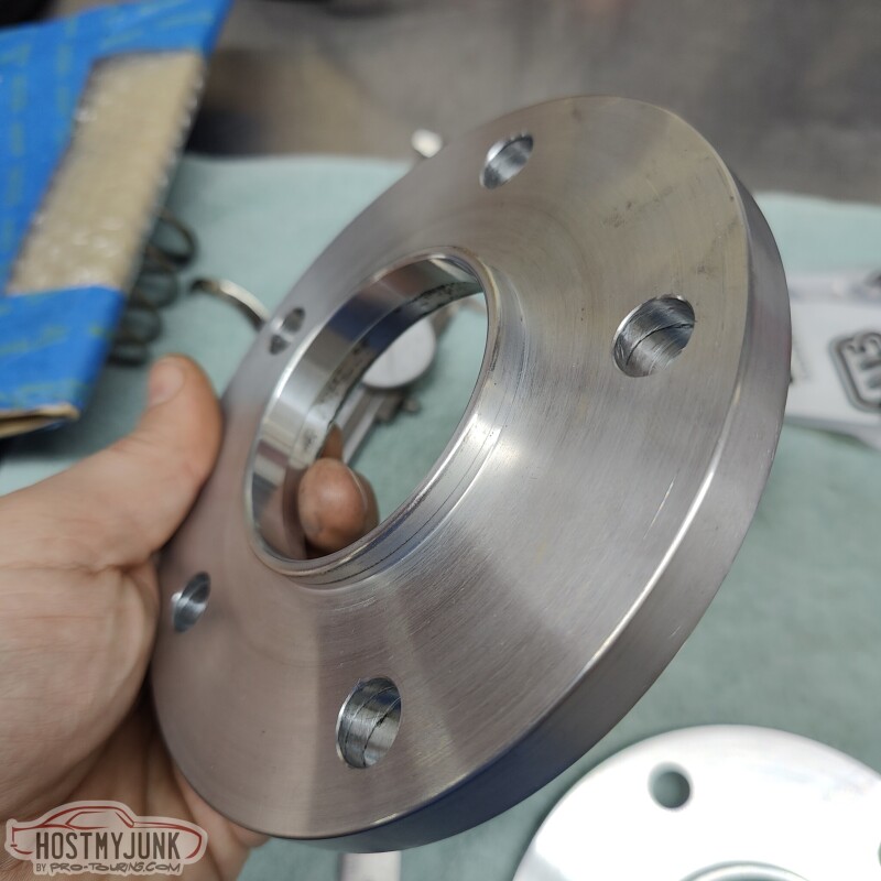
The fit was spot on.
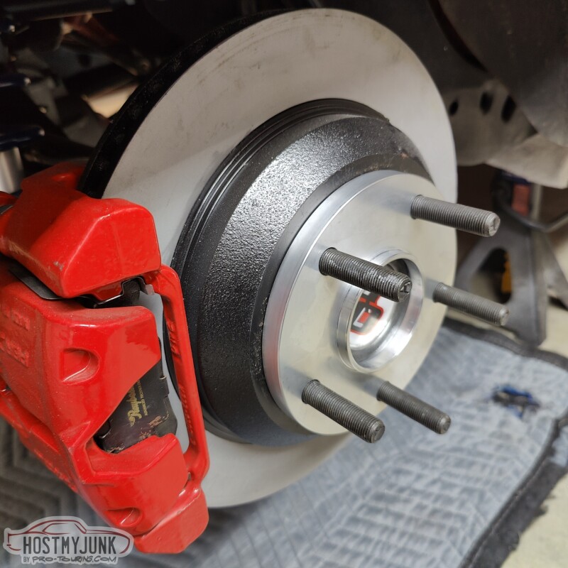
I added this spacer to center the tire in the wheel wells. There is about 1.5" from the tire to the frame on the inside and about 1" on the outside. Also, both sides looked the same, which means the axle is well centered in the chassis and the body is well placed on the frame.
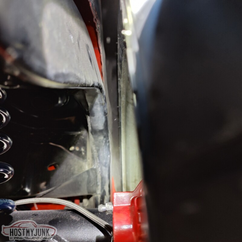
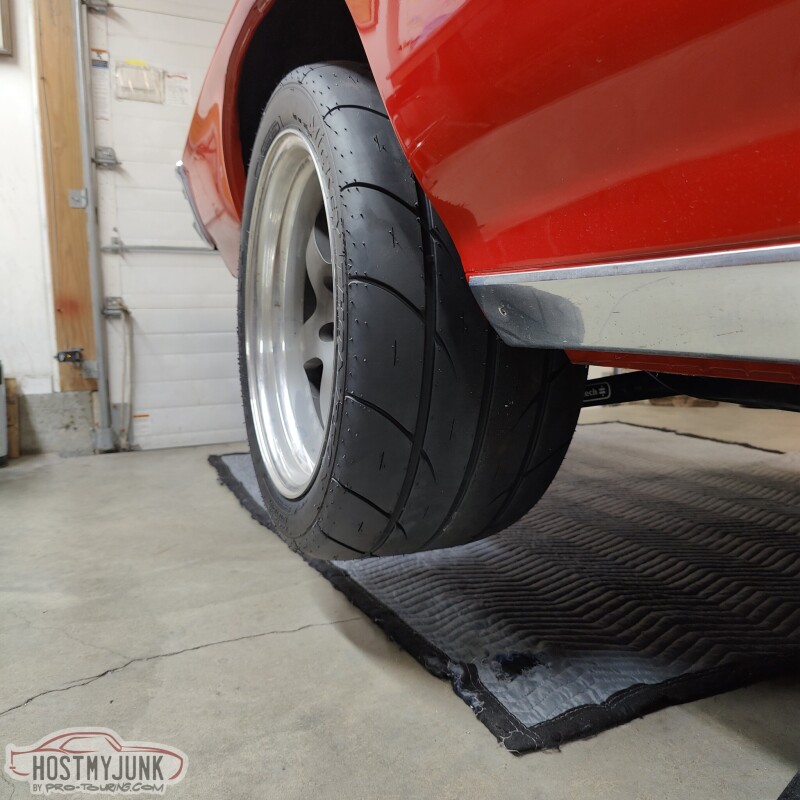
The Mickey Thompson ET Street SS tires look amazing! The rear end is in full droop in this picture. Ride height is still to be determined.
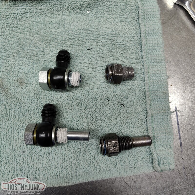
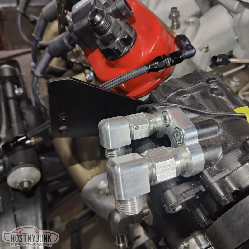
After the fun stuff, it was down to a rather tedious project. These are some banjo -AN adapters for the transmission cooler lines, compared to the stock adapters on the right.
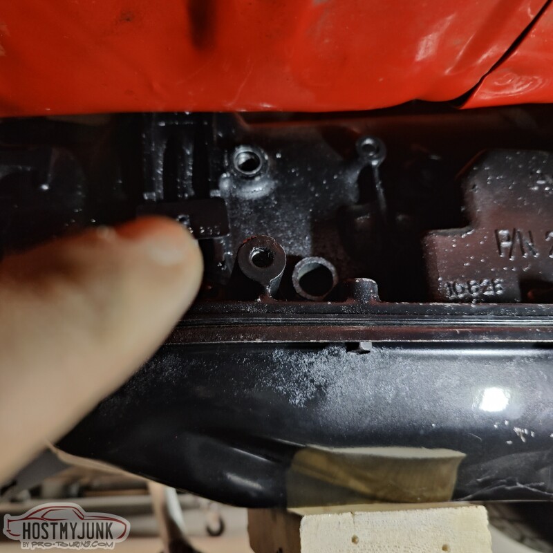
See that hole at the top?
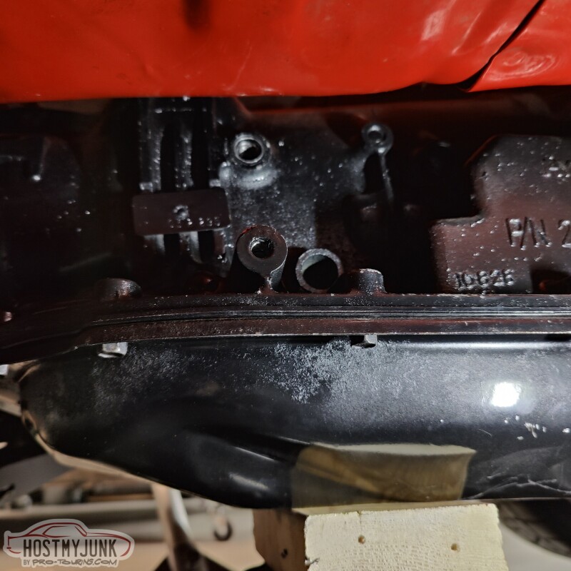
That one...That is where the longer fitting has to go, and there isn't enough room in the transmission tunnel to take the fitting out. So I had to remove the transmission crossmember and lower the trans in order to install these. This picture is with the transmission at full droop.
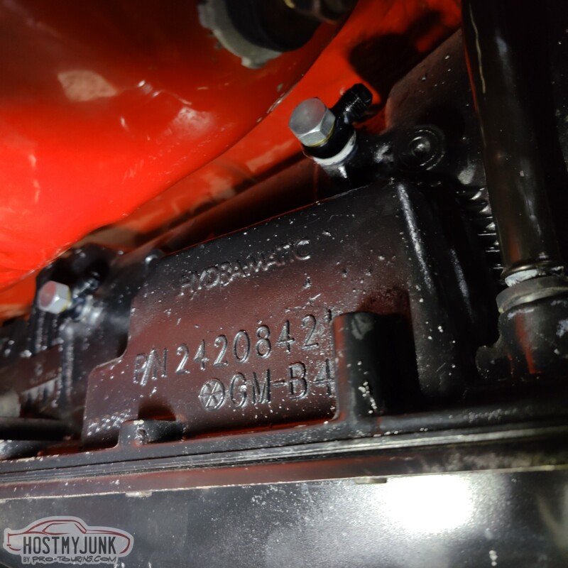
Here they are installed with the transmission back in place.
Then I got to looking at the intercooler and grabbed a gray scuff pad and started to rub. I really like the brushed look for the intercooler, so I will use the gray scuff pad over all of it and leave it a natural brushed finish (the rest is bead blasted for now).
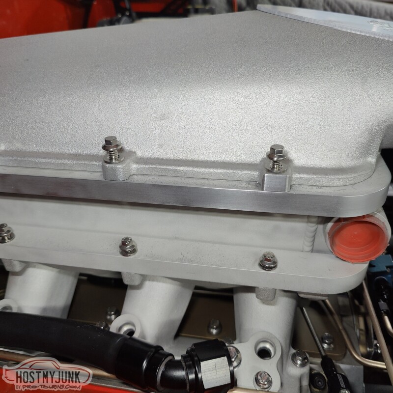
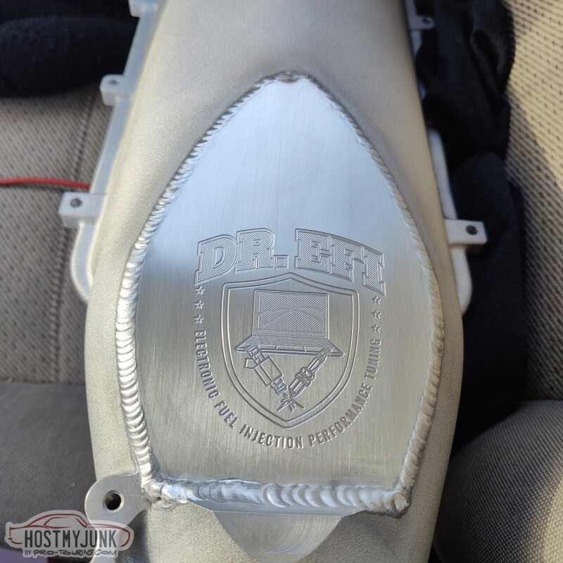
A big "Thank you" to one of my customers, who graciously engraved my logo into the intake manifold plate.
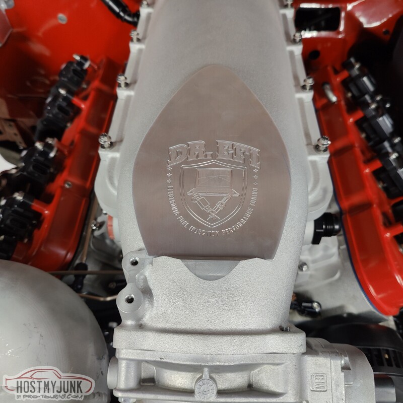
She is starting to look like something!
Andrew
The fit was spot on.
I added this spacer to center the tire in the wheel wells. There is about 1.5" from the tire to the frame on the inside and about 1" on the outside. Also, both sides looked the same, which means the axle is well centered in the chassis and the body is well placed on the frame.
The Mickey Thompson ET Street SS tires look amazing! The rear end is in full droop in this picture. Ride height is still to be determined.
After the fun stuff, it was down to a rather tedious project. These are some banjo -AN adapters for the transmission cooler lines, compared to the stock adapters on the right.
See that hole at the top?
That one...That is where the longer fitting has to go, and there isn't enough room in the transmission tunnel to take the fitting out. So I had to remove the transmission crossmember and lower the trans in order to install these. This picture is with the transmission at full droop.
Here they are installed with the transmission back in place.
Then I got to looking at the intercooler and grabbed a gray scuff pad and started to rub. I really like the brushed look for the intercooler, so I will use the gray scuff pad over all of it and leave it a natural brushed finish (the rest is bead blasted for now).
A big "Thank you" to one of my customers, who graciously engraved my logo into the intake manifold plate.
She is starting to look like something!
Andrew

The following 4 users liked this post by Project GatTagO:
2ToeRacing (07-16-2023), Jimbo1367 (01-24-2023), LS1Formulation (02-02-2023), truckdoug (01-23-2023)
01-21-2023, 10:52 PM
#622
TECH Senior Member

Looking VERY GOOD, Andrew!!
The following users liked this post:
Project GatTagO (01-22-2023)
01-23-2023, 11:27 AM
#623

Loving the progress on this. I thought v2.0 was pretty awesome already, but you're really stepping up on the details. What is to become of the shaker hood intake? That was one of my favorite aspects of your old build. I don't suppose there will be a functional shaker intake with this new combo.

The following 3 users liked this post by LS1 TJ:
01-23-2023, 10:15 PM
#625
TECH Senior Member
Thread Starter
iTrader: (7)
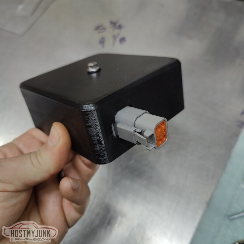
This morning I received this 4 cavity Deutsch bulkhead connector from Prowireusa. They are one of my Go-to vendors for wiring products.
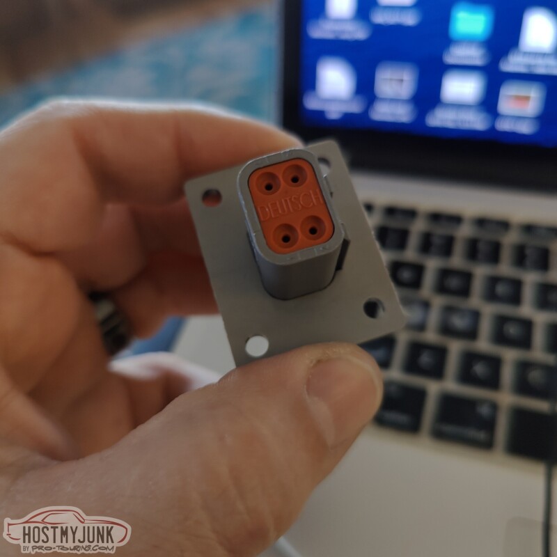
The idea behind getting this connector is that I would be able to wire the boost control solenoids to this connector and have a neat way of connecting them to the rest of the engine harness.
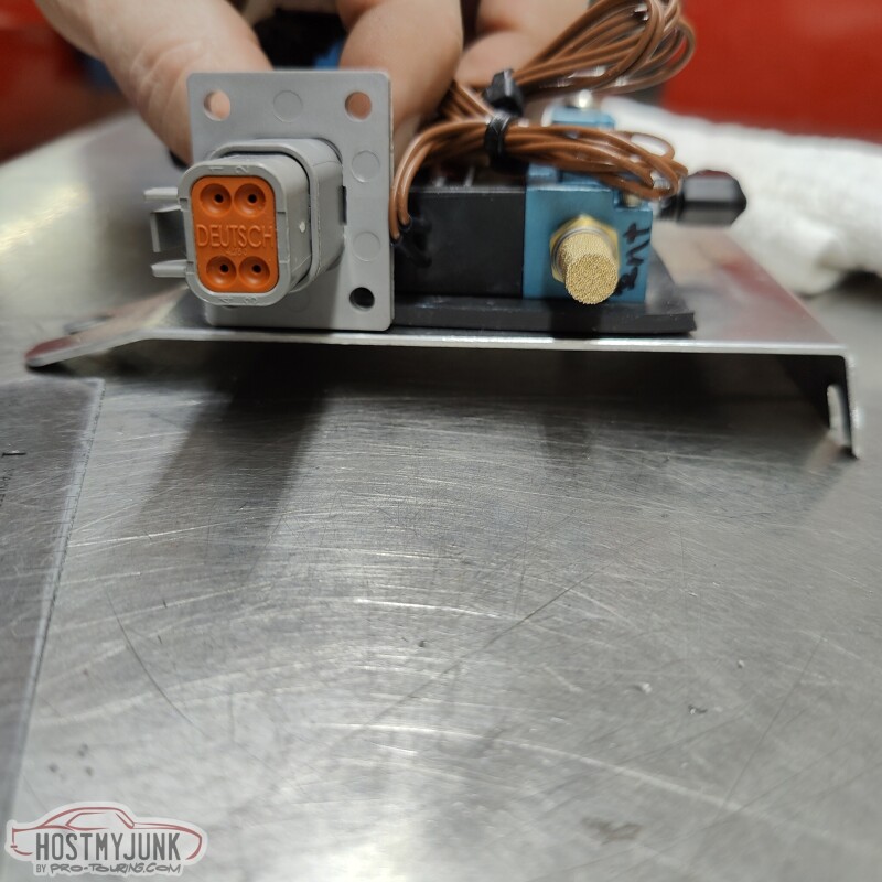
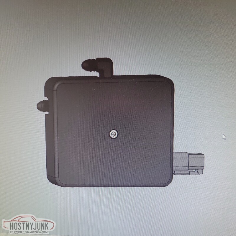
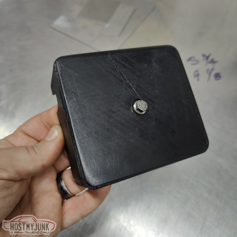
My friend Blake designed this little cover for the boost solenoids and it will hold the bulkhead connector in place and also give the solenoids a much cleaner look. He is also going to 3D print the cover.
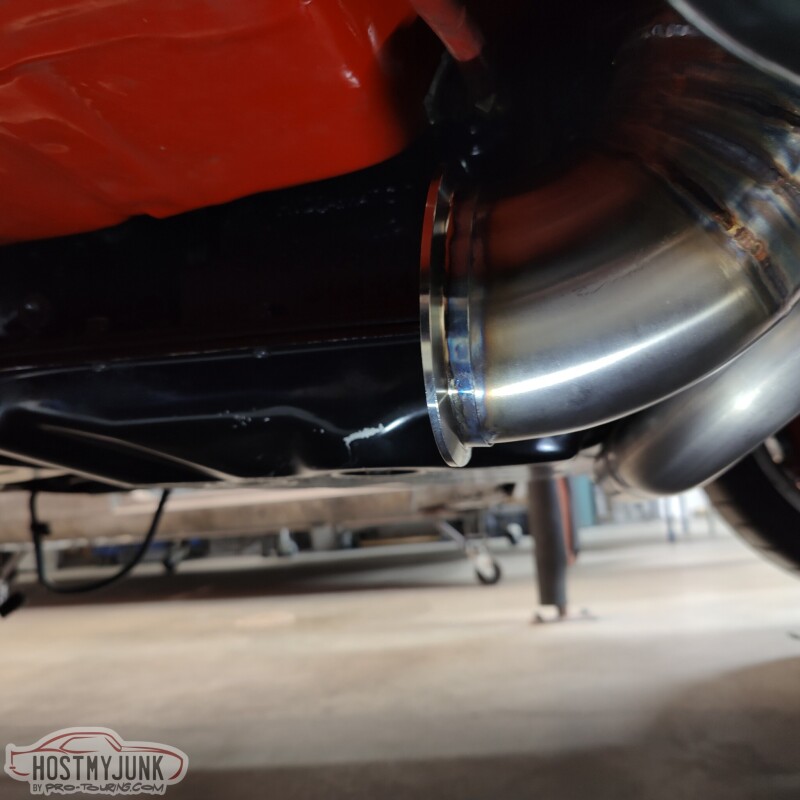
Vic also added an elbow to the end of the downpipe with a v-band. The rest of the exhaust system will be built from here back.
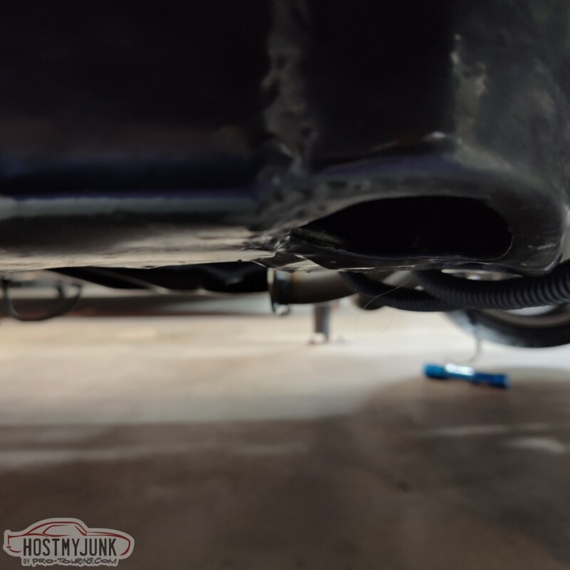
This is a terrible picture, but I was just trying to show that the downpipe doesn't hang very low. In fact, the crossover pipe from the driver's exhaust manifold is the lowest point under the car.
Vic also made some adjustments to the short pipe that goes from the wastegate into the downpipe. It was about 3/32" too short which made it difficult to install the v-band. Vic cut that pipe, sleeved it, and welded it all back together.
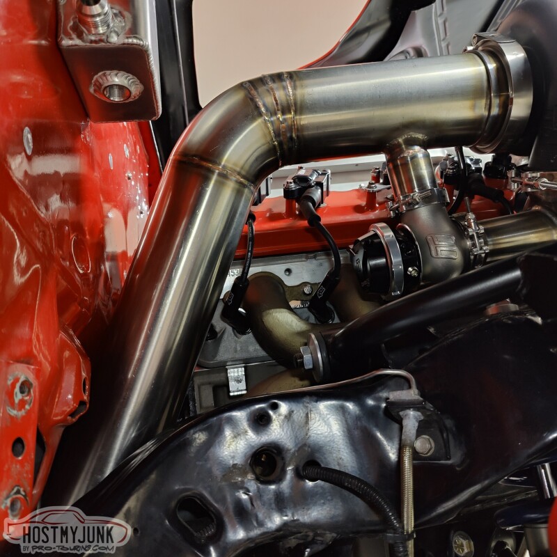
You can better see the sleeve here.
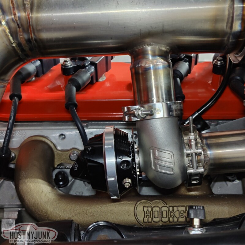
He also added a small tab to keep the downpipe more stable.
Tomorrow is a big day and I can't wait to share what we have planned.
Andrew
The idea behind getting this connector is that I would be able to wire the boost control solenoids to this connector and have a neat way of connecting them to the rest of the engine harness.
My friend Blake designed this little cover for the boost solenoids and it will hold the bulkhead connector in place and also give the solenoids a much cleaner look. He is also going to 3D print the cover.
Vic also added an elbow to the end of the downpipe with a v-band. The rest of the exhaust system will be built from here back.
This is a terrible picture, but I was just trying to show that the downpipe doesn't hang very low. In fact, the crossover pipe from the driver's exhaust manifold is the lowest point under the car.
Vic also made some adjustments to the short pipe that goes from the wastegate into the downpipe. It was about 3/32" too short which made it difficult to install the v-band. Vic cut that pipe, sleeved it, and welded it all back together.
You can better see the sleeve here.
He also added a small tab to keep the downpipe more stable.
Tomorrow is a big day and I can't wait to share what we have planned.
Andrew
The following 2 users liked this post by Project GatTagO:
2ToeRacing (07-16-2023), G Atsma (01-23-2023)
01-24-2023, 06:50 PM
#626
TECH Senior Member
Thread Starter
iTrader: (7)
I love this country. Yesterday I made a call to a local company and this morning a guy named Matthew showed up with a big computer.
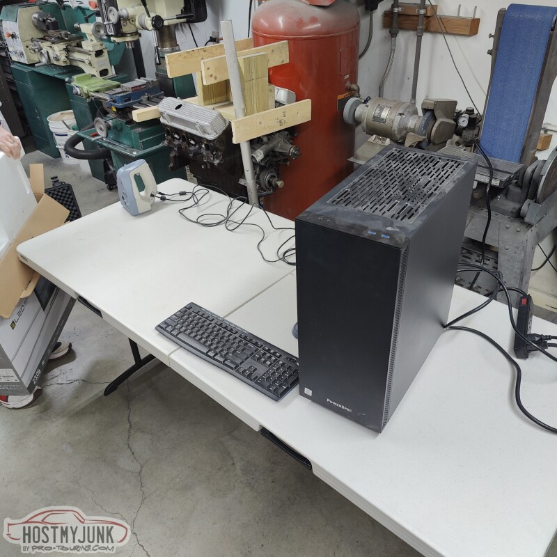
and a 3D scanner...
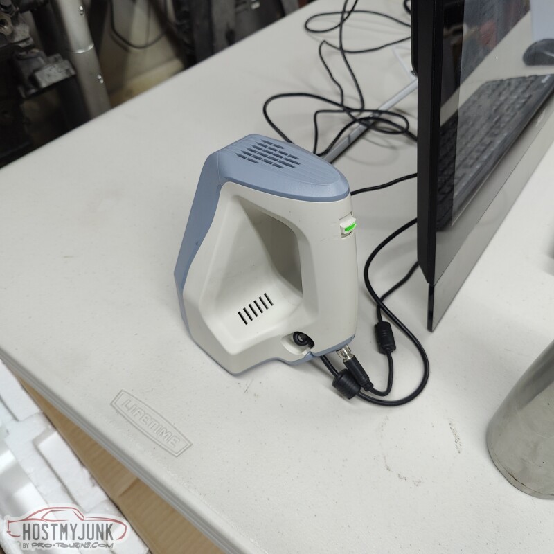
and a bag of cocaine...(just kidding...baby powder) The baby powder was used extensively to knock the shine off the finish.
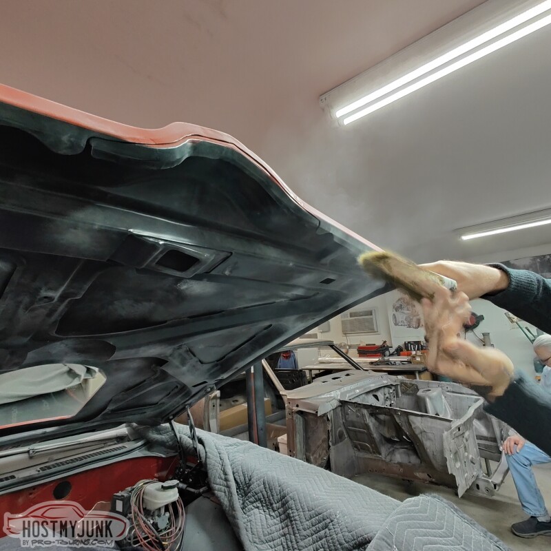
Then he proceeded to start scanning the bottom and the top of the hood. The purpose was to crate an accurate model that can the be used to design various options for the hole in the hood.
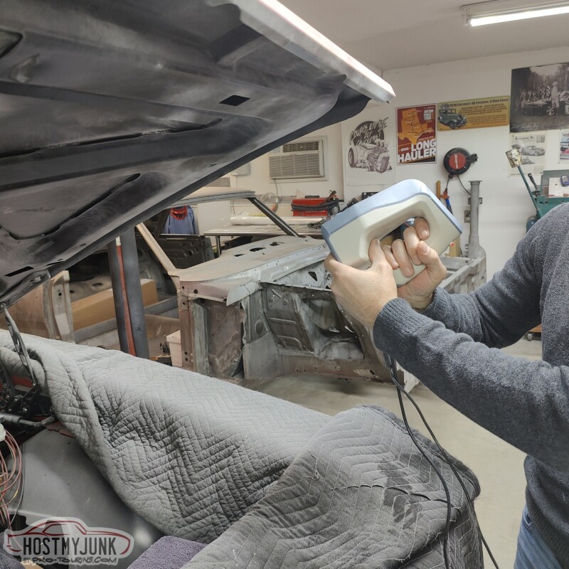
This is at the start of the process and it took about 4 hours to do the whole hood. In a few days I should have a cleaned up 3D model of the hood.

While Matthew was doing the scanning, I decided to install the new automatic brake pedal. Before installing it, I took some measurements to check the pedal ratio with the existing holes. The top (manual brakes) hole gives about a 6.5:1 pedal ratio. The bottom hole (stock power brakes) gives about a 3.5:1 pedal ratio.
The various information that I could find about the iBooster said that the Tesla pedal ratio is 4:1. So we added an extra hole just above the stock lower hole, which resulted in about a 4.25:1 pedal ratio. This was about as close as we could come given the proximity to the lower hole.
This change resulted in a much more favorable angle for the pushrod.
Andrew
and a 3D scanner...
and a bag of cocaine...(just kidding...baby powder) The baby powder was used extensively to knock the shine off the finish.
Then he proceeded to start scanning the bottom and the top of the hood. The purpose was to crate an accurate model that can the be used to design various options for the hole in the hood.
This is at the start of the process and it took about 4 hours to do the whole hood. In a few days I should have a cleaned up 3D model of the hood.
While Matthew was doing the scanning, I decided to install the new automatic brake pedal. Before installing it, I took some measurements to check the pedal ratio with the existing holes. The top (manual brakes) hole gives about a 6.5:1 pedal ratio. The bottom hole (stock power brakes) gives about a 3.5:1 pedal ratio.
The various information that I could find about the iBooster said that the Tesla pedal ratio is 4:1. So we added an extra hole just above the stock lower hole, which resulted in about a 4.25:1 pedal ratio. This was about as close as we could come given the proximity to the lower hole.
This change resulted in a much more favorable angle for the pushrod.
Andrew
The following users liked this post:
2ToeRacing (07-16-2023)
01-25-2023, 07:15 AM
#627

The following users liked this post:
Project GatTagO (01-26-2023)
01-26-2023, 05:29 PM
#628
TECH Senior Member
Thread Starter
iTrader: (7)
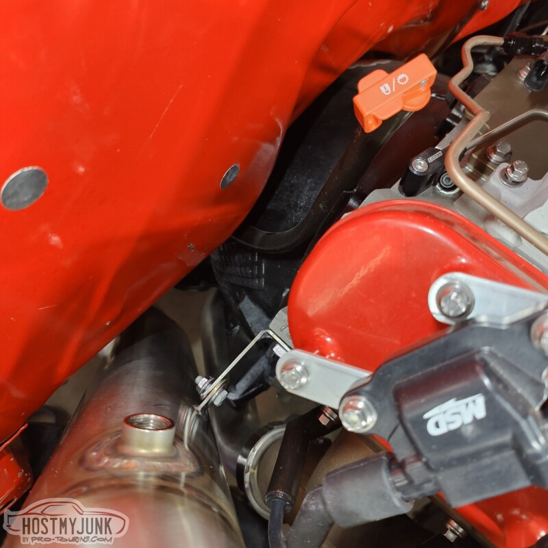
Progress is being made. Yesterday I sent off the up-pipe and the downpipe to HeaderShield to have them wrapped. Today I showed up at Vic's and saw that he had installed the firewall shield that we had been discussing. We will probably take the intake off and go all the way across as much as we can with it.
I also pulled the drive's side seat to start mocking up the shifter. What you don't see is that under the carpet I had removed the shifter hump that was installed 20 years ago to make room for the Richmond 6 speed shifter. With that hump gone (it was bolted in) the console that I plan to use actually sort of fits. I ordered a partial left side front floor patch panel that includes part of the transmission tunnel. We are going to use that to close off the hole and have the shape of the floor be how it was with an auto trans. Then the 70 Chevelle console that I got should fit a lot better.
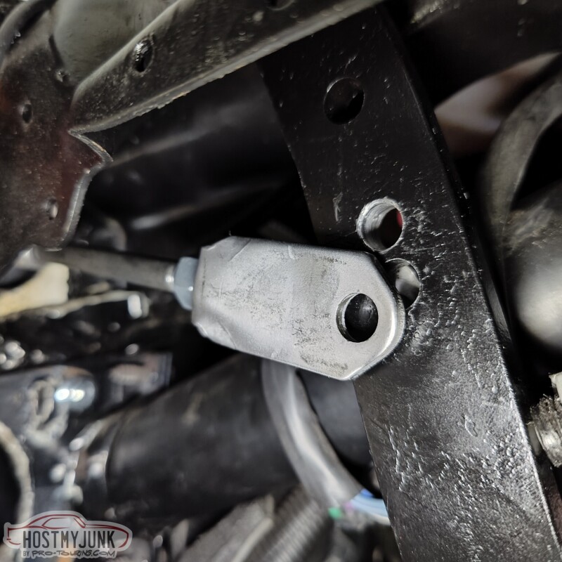
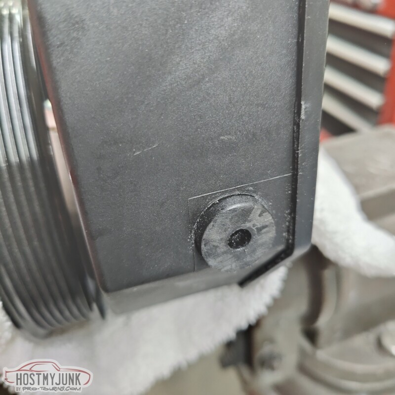
In order to do the power steering plumbing, this little nipple for the fluid return had to be cut off because it was pointing right at the steering box.
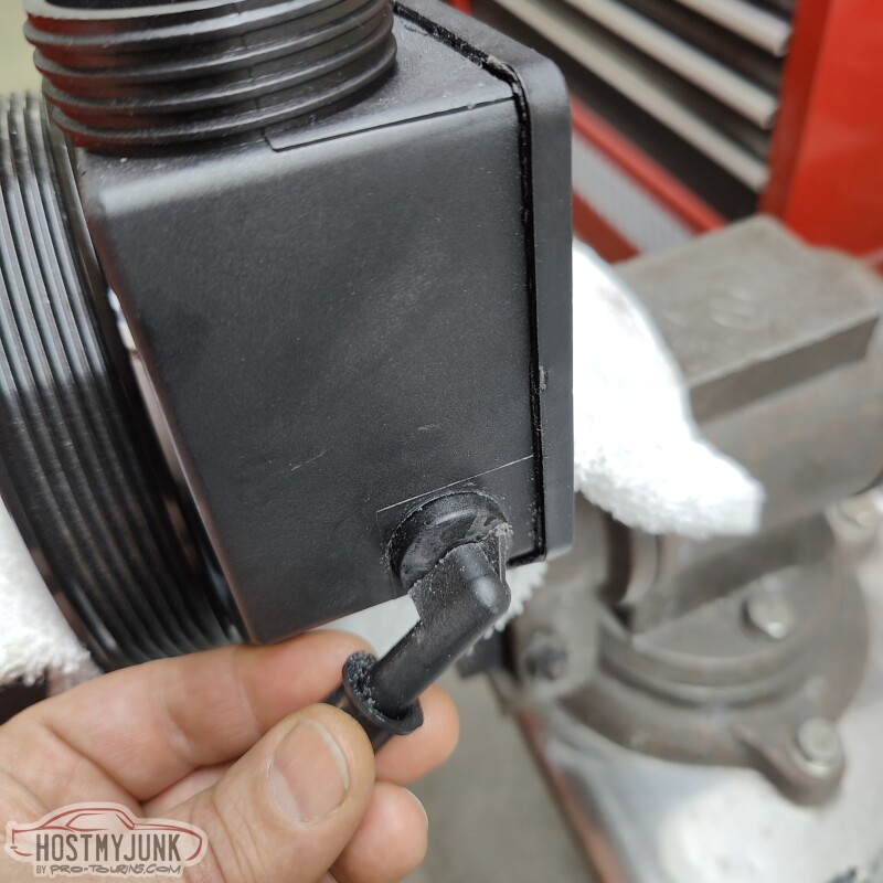
The hole is quite small, so we are going to install a 1/8" NPT to AN-6 fitting there.
Andrew
I also pulled the drive's side seat to start mocking up the shifter. What you don't see is that under the carpet I had removed the shifter hump that was installed 20 years ago to make room for the Richmond 6 speed shifter. With that hump gone (it was bolted in) the console that I plan to use actually sort of fits. I ordered a partial left side front floor patch panel that includes part of the transmission tunnel. We are going to use that to close off the hole and have the shape of the floor be how it was with an auto trans. Then the 70 Chevelle console that I got should fit a lot better.
In order to do the power steering plumbing, this little nipple for the fluid return had to be cut off because it was pointing right at the steering box.
The hole is quite small, so we are going to install a 1/8" NPT to AN-6 fitting there.
Andrew
The following users liked this post:
G Atsma (01-26-2023)
01-29-2023, 12:55 PM
#629
TECH Senior Member
Thread Starter
iTrader: (7)
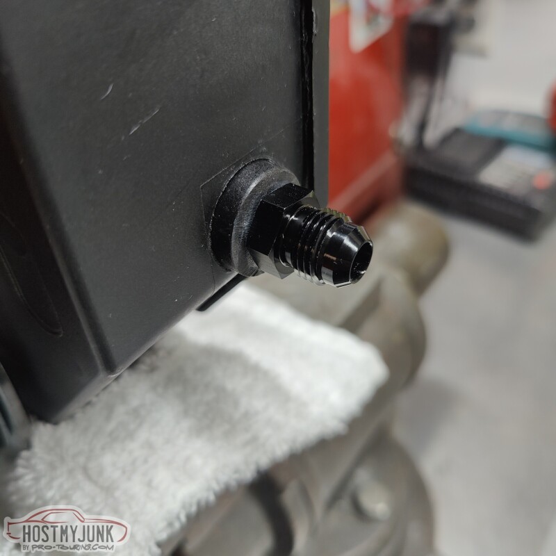
A quick trip to Star Performance produced the 1/8" NPT to AN-6 Male fitting, and the power steering return is now sorted.
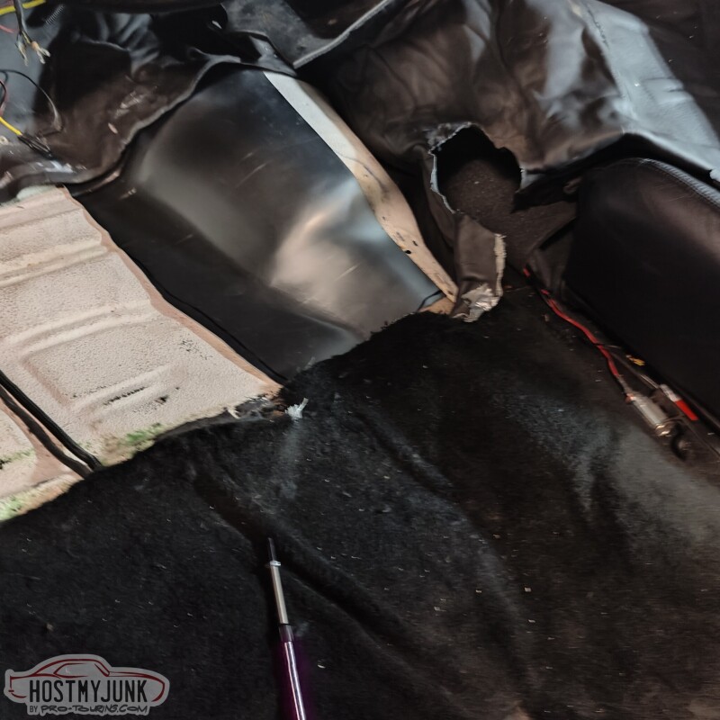
The next project to tackle was this hole in the side of the transmission tunnel.
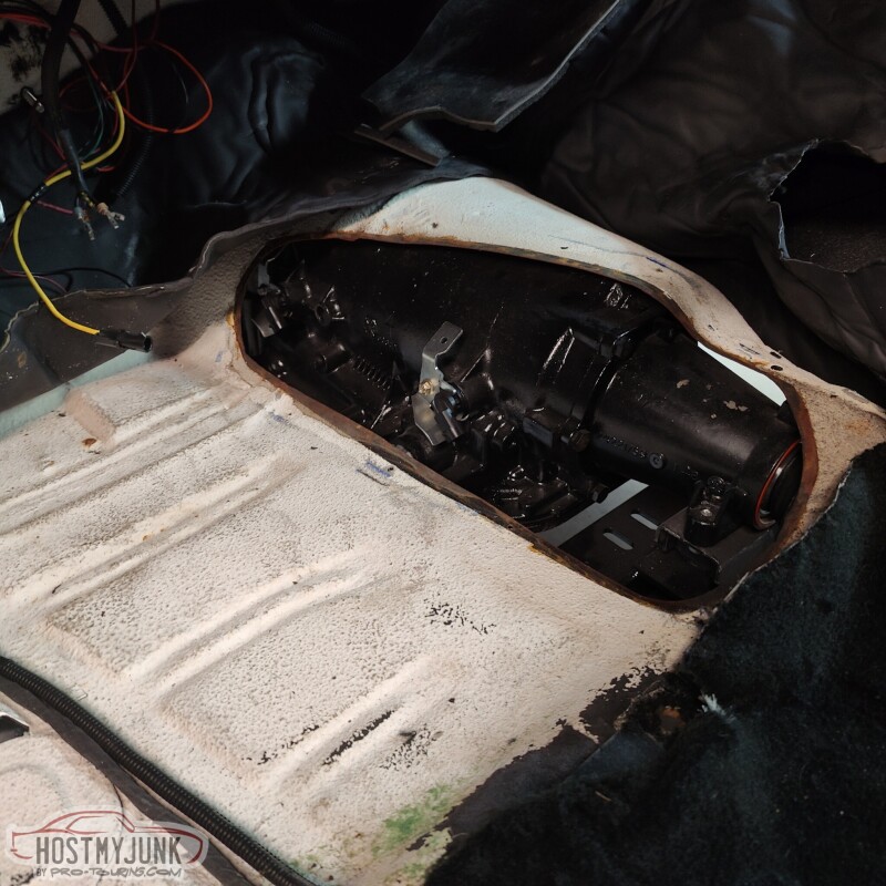
The hole used to have a cover that had a shifter hump in it to clear the shifter and linkage for the Richmond 6 speed that used to be in the car. With that transmission gone and the 4L80e in its place, a new cover needed to be made.
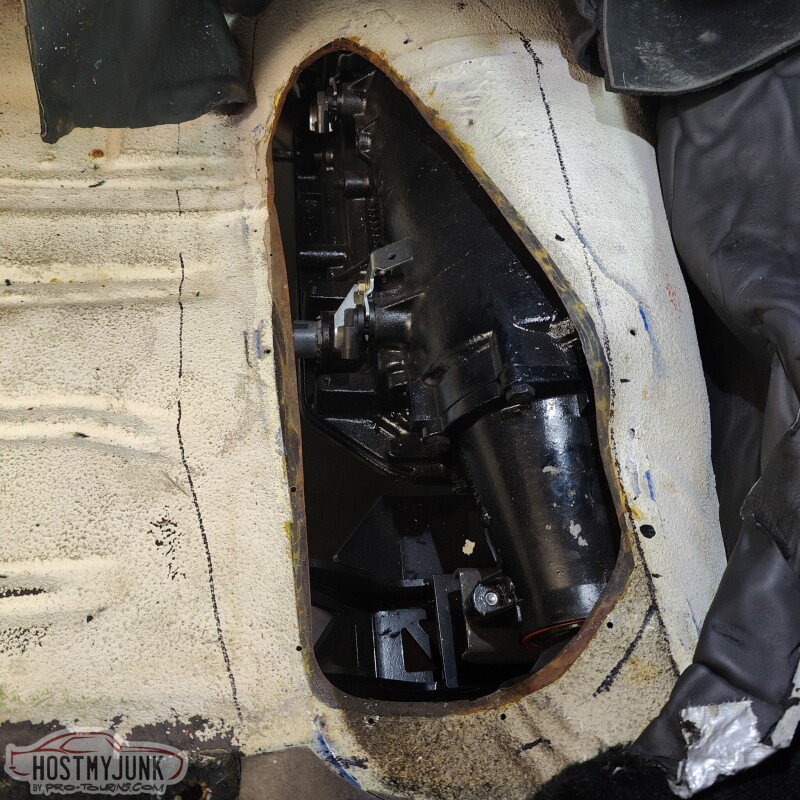
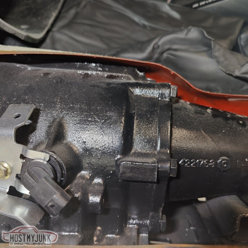
Here you can see how close the transmission is to the trans tunnel. My body bushings are 20 years old. They are not cracked, but I am sure they have settled some, which is contributing to the lack of clearance.
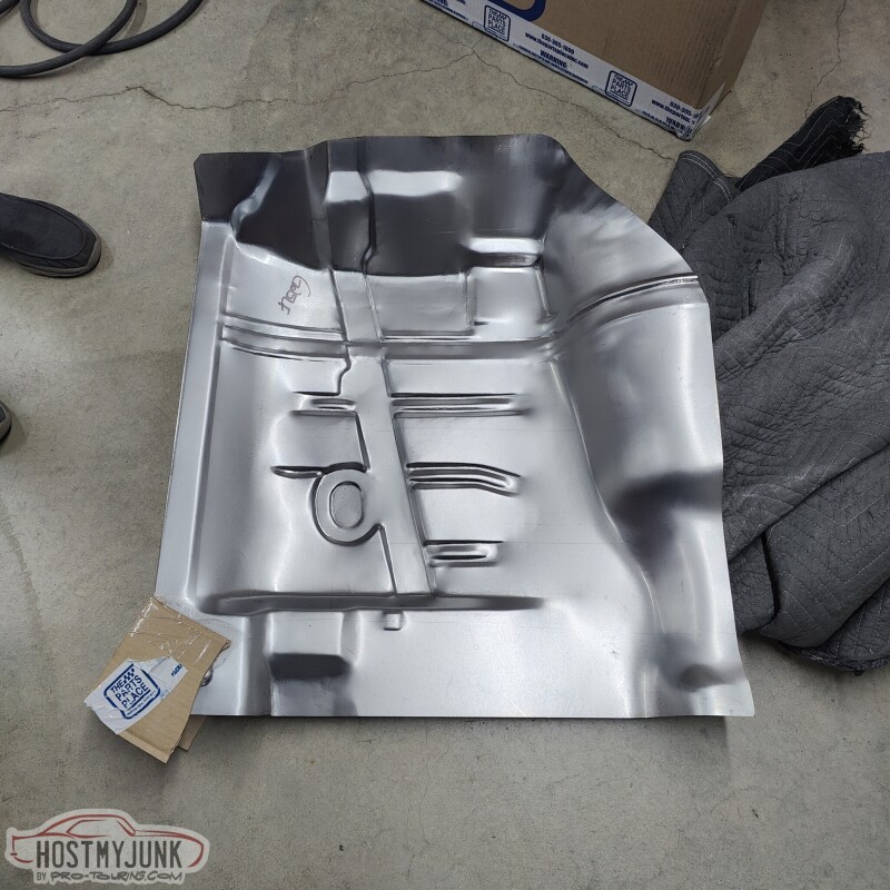
A quick Google search showed that partial floor pan patch panels were readily available. I called The Parts Place and they had one in stock and had it at my door in two days. You can see that part of the panel includes the needed piece to start making a new cover for the tunnel.
I trimmed it big to start...
Then trimmed it to the final shape...
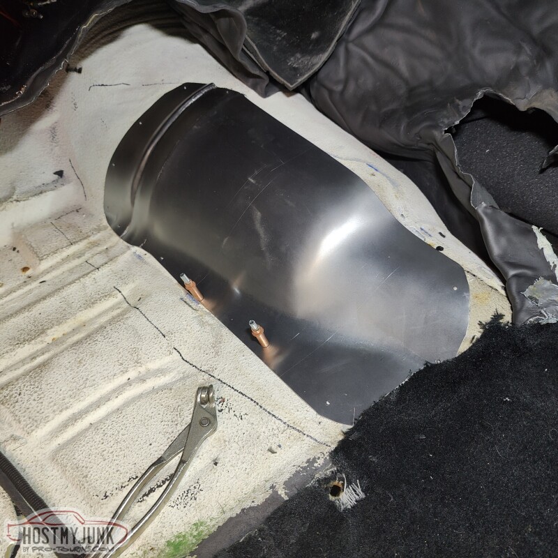
and started to drill the necessary mounting holes.
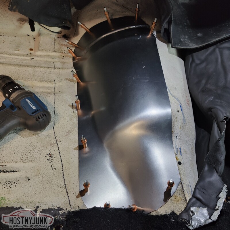
Turned out pretty good in the end, without having to do any custom metal shaping, which I don't have the skills to do anyway....
Andrew
The next project to tackle was this hole in the side of the transmission tunnel.
The hole used to have a cover that had a shifter hump in it to clear the shifter and linkage for the Richmond 6 speed that used to be in the car. With that transmission gone and the 4L80e in its place, a new cover needed to be made.
Here you can see how close the transmission is to the trans tunnel. My body bushings are 20 years old. They are not cracked, but I am sure they have settled some, which is contributing to the lack of clearance.
A quick Google search showed that partial floor pan patch panels were readily available. I called The Parts Place and they had one in stock and had it at my door in two days. You can see that part of the panel includes the needed piece to start making a new cover for the tunnel.
I trimmed it big to start...
Then trimmed it to the final shape...
and started to drill the necessary mounting holes.
Turned out pretty good in the end, without having to do any custom metal shaping, which I don't have the skills to do anyway....
Andrew
02-01-2023, 09:36 PM
#630
TECH Senior Member
Thread Starter
iTrader: (7)
I took my intake to Hot Rod Express, where they welded the engraved manifold cover plate to the Holley intake lid.
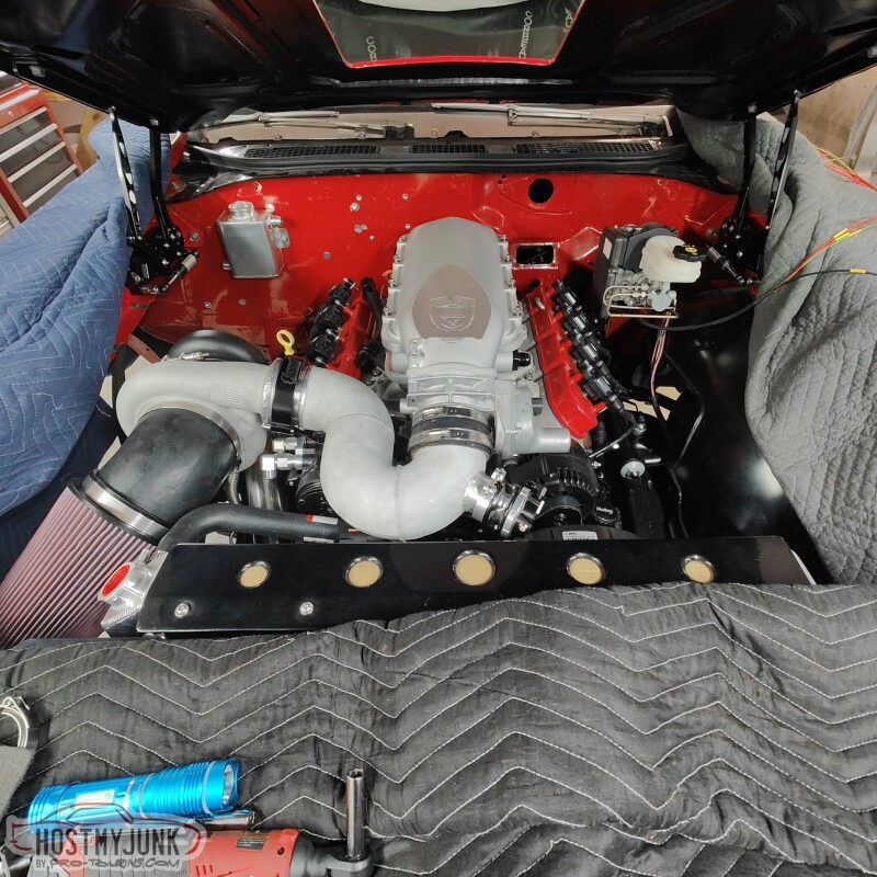
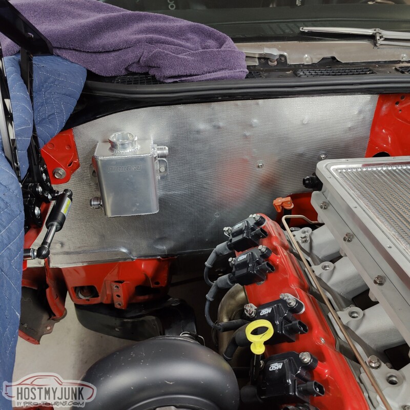
Today was the day that I wanted to get the heat exchanger mounted and start thinking about running the plumbing (so much plumbing in this car!!!) the A2W intercooler system. When I originally asked Vic to mount the heat exchanger to the radiator, I really had no idea how things would be plumbed. I had him mount the heat exchanger with the inlet and outlet (dual pass) on the driver's side. Clearly this is not going to work.
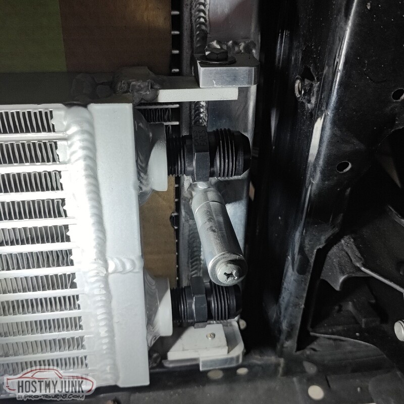
With the intercooler, fill tank, and circulation pump in place, it was clear that the best option would be to have the input and outlet on the passenger side. Before digging into that further I wanted to make sure that the circulation pump fittings would be oriented in the correct direction. I emailed Tobias at Tecomotive and he quickly responded that the pump inlet and outlet cover can be clocked in any of the 4 positions relative to the pump body.
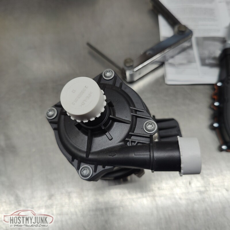
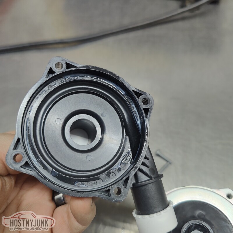
I unscrewed the top and it sure doesn't look very fancy in here, but this pump is supposed to move A LOT of water.
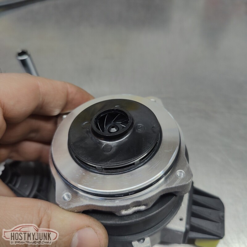
Not much to see here....
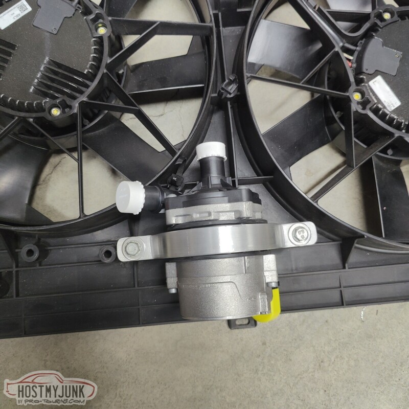
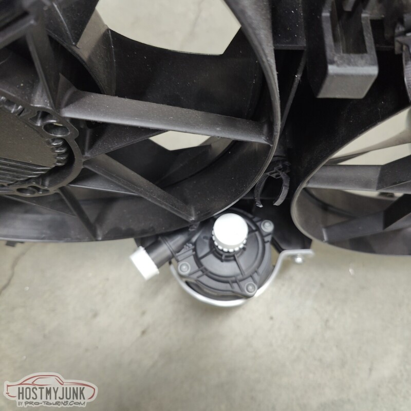
I positioned the pump body in such a way that the connector was close to the fan shroud so that the wires for the pump could be routed along the bottom of the shroud.
I clocked the top so the outlet would face the passenger side (the top is the inlet).
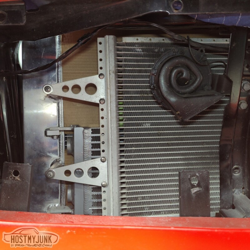
I also pulled both grill inserts so it would be easier to work in front of the radiator. As I was going along, I always had to make sure that I could get to everything without having to pull the grills, because once the radiator is installed, there is no way to access the grill hardware.
Here you can see that the heat exchanger was flipped (the drain is now at the top and can't be used). We couldn't rotate the heat exchanger because that would have required a complete reworking of the mounts and I did not want to do all that. I can live without a drain.
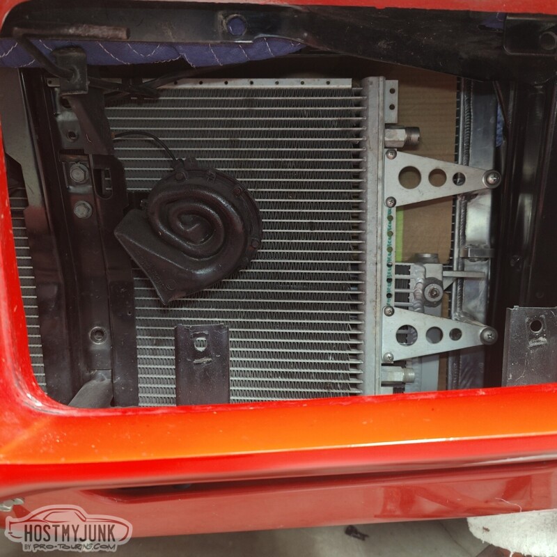
There is a lot more room on the passenger side for plumbing because the radiator core is slightly offset to the driver's side (note the larger tank on the passenger side).
With that orientation locked in, we moved to the bench where some minor fiddling had to be done to make the mounts work.
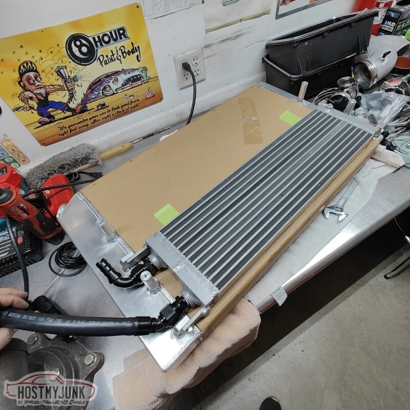
Both the inlet and outlet hoses fit pretty well using 90 degree fittings. With the fans removed and the radiator top tilted back, there is enough room to access these fittings from the top.
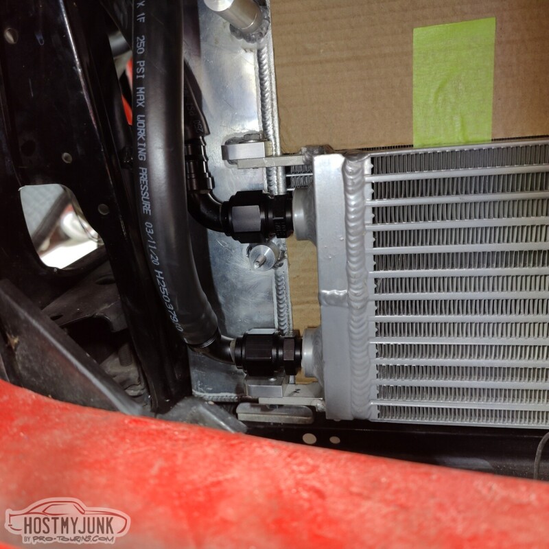
I also trimmed the core support slightly so that the hoses can pass in front of the radiator. You can also see the Low Doller Motorsports temperature/pressure combo sensor in the cooling system.
I still have to finalize the exact hose routing, but this is pretty good progress.
Andrew
Today was the day that I wanted to get the heat exchanger mounted and start thinking about running the plumbing (so much plumbing in this car!!!) the A2W intercooler system. When I originally asked Vic to mount the heat exchanger to the radiator, I really had no idea how things would be plumbed. I had him mount the heat exchanger with the inlet and outlet (dual pass) on the driver's side. Clearly this is not going to work.
With the intercooler, fill tank, and circulation pump in place, it was clear that the best option would be to have the input and outlet on the passenger side. Before digging into that further I wanted to make sure that the circulation pump fittings would be oriented in the correct direction. I emailed Tobias at Tecomotive and he quickly responded that the pump inlet and outlet cover can be clocked in any of the 4 positions relative to the pump body.
I unscrewed the top and it sure doesn't look very fancy in here, but this pump is supposed to move A LOT of water.
Not much to see here....
I positioned the pump body in such a way that the connector was close to the fan shroud so that the wires for the pump could be routed along the bottom of the shroud.
I clocked the top so the outlet would face the passenger side (the top is the inlet).
I also pulled both grill inserts so it would be easier to work in front of the radiator. As I was going along, I always had to make sure that I could get to everything without having to pull the grills, because once the radiator is installed, there is no way to access the grill hardware.
Here you can see that the heat exchanger was flipped (the drain is now at the top and can't be used). We couldn't rotate the heat exchanger because that would have required a complete reworking of the mounts and I did not want to do all that. I can live without a drain.
There is a lot more room on the passenger side for plumbing because the radiator core is slightly offset to the driver's side (note the larger tank on the passenger side).
With that orientation locked in, we moved to the bench where some minor fiddling had to be done to make the mounts work.
Both the inlet and outlet hoses fit pretty well using 90 degree fittings. With the fans removed and the radiator top tilted back, there is enough room to access these fittings from the top.
I also trimmed the core support slightly so that the hoses can pass in front of the radiator. You can also see the Low Doller Motorsports temperature/pressure combo sensor in the cooling system.
I still have to finalize the exact hose routing, but this is pretty good progress.
Andrew
The following 2 users liked this post by Project GatTagO:
2ToeRacing (07-16-2023), nleming (02-01-2023)

The following 3 users liked this post by Toddoky:
02-02-2023, 02:25 AM
#632

Andrew,
I�m surprised you didn�t mention the pin hole leftover from having the intake welded. I can�t believe a professional shop sent the out the door like that. I assume they made sure it didn�t leak, It�s just a complete eyesore and looks bad for their workmanship.
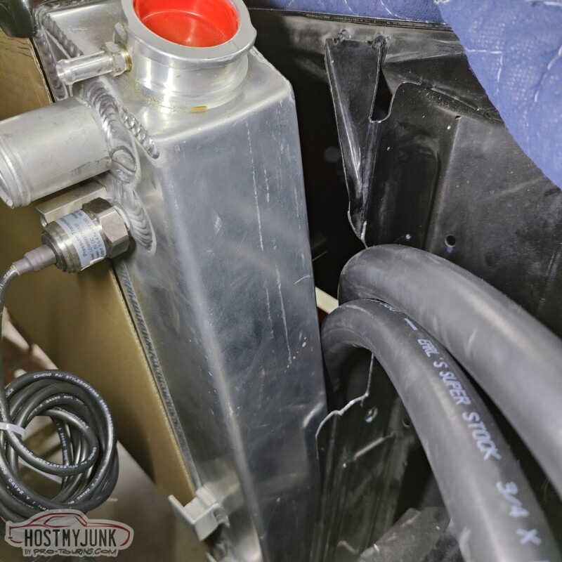
I really like the way the EARLS super stock hose and fitting look. What brand heat exchanger is that? I don�t recall.
thanks,
jimbo
I�m surprised you didn�t mention the pin hole leftover from having the intake welded. I can�t believe a professional shop sent the out the door like that. I assume they made sure it didn�t leak, It�s just a complete eyesore and looks bad for their workmanship.
I really like the way the EARLS super stock hose and fitting look. What brand heat exchanger is that? I don�t recall.
thanks,
jimbo
02-02-2023, 08:02 AM
#633
TECH Senior Member
Thread Starter
iTrader: (7)
Andrew,
I�m surprised you didn�t mention the pin hole leftover from having the intake welded. I can�t believe a professional shop sent the out the door like that. I assume they made sure it didn�t leak, It�s just a complete eyesore and looks bad for their workmanship.
I really like the way the EARLS super stock hose and fitting look. What brand heat exchanger is that? I don�t recall.
thanks,
jimbo
The heat exchanger is from Frozen Boost.
Andrew
02-03-2023, 10:01 PM
#634
TECH Senior Member
Thread Starter
iTrader: (7)
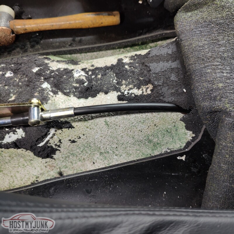
I had mocked up the shifter a while back and it turned out that the 4 foot cable that was included with the Lokar shifter was not going to be long enough. So I ordered a 6 foot cable (which honestly could be 7 feet) from Summit and after it was defrosted in the Texas warehouse, I received it yesterday.
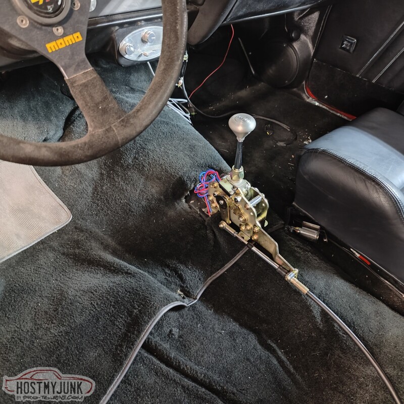
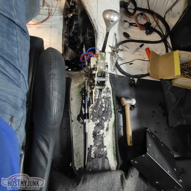
So it was time to put the big boy pants on and poke some holes to mount the shifter. I positioned it in such a way that with the shifter in Drive, I could, very naturally, put my hand on the shift level and slide it to the right and use the forward and backwards tap shift feature.
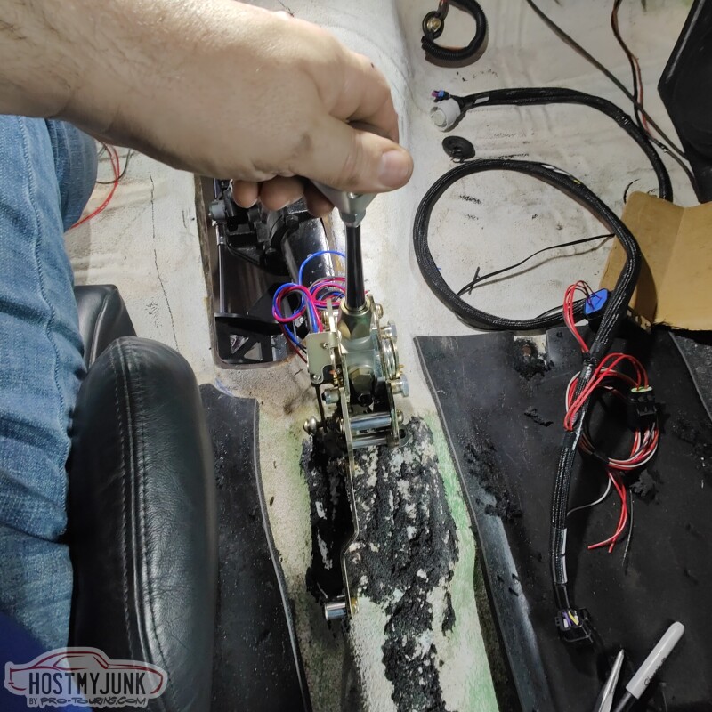
I drilled the first hole and shockingly it lined up perfectly where I intended it to go. I mounted the shifter and marked the other hole.
I used nut-serts (riv-nuts) inside the hole and temporarily mounted the shifter.
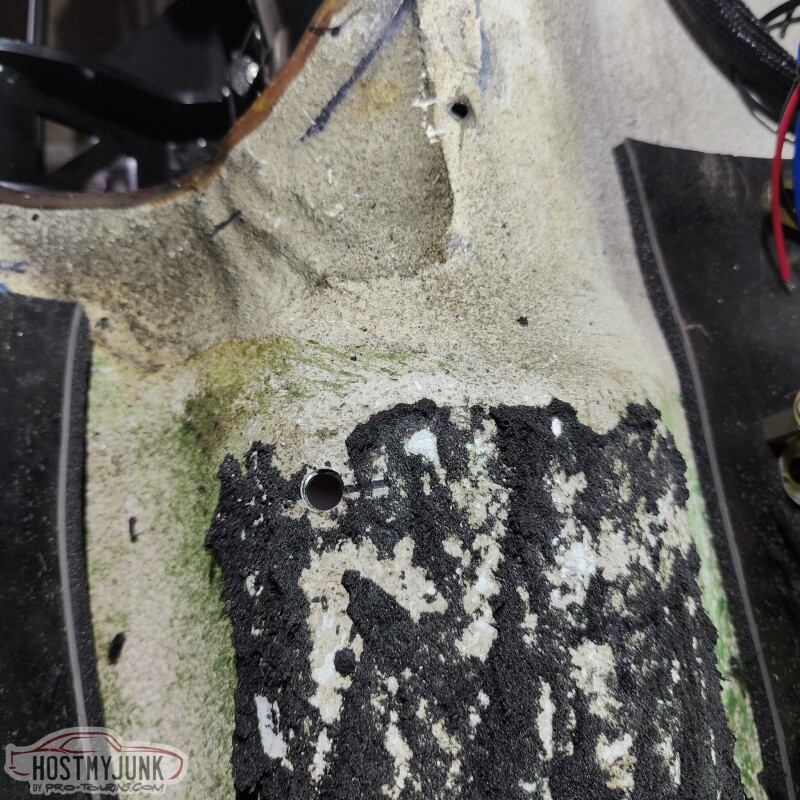
I did a little more measuring and drilled a hole in the floor for the shifter cable. ICT Billet posted a teaser on their Instagram about their new shift cable pass-through and I have been bugging them about it for weeks. I am hoping it will be available soon so I can use it to seal the hole.
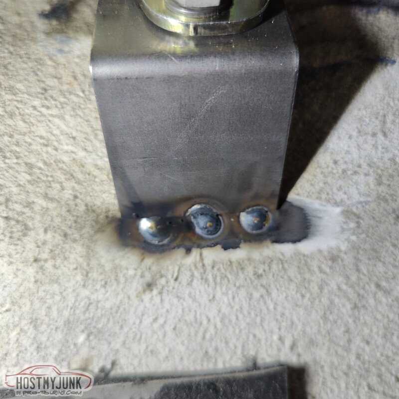
For the front of the shifter, Vic whipped up a simple bracket and we (yes, I welded one side and he the other...thanks you...) welded it to the floor.
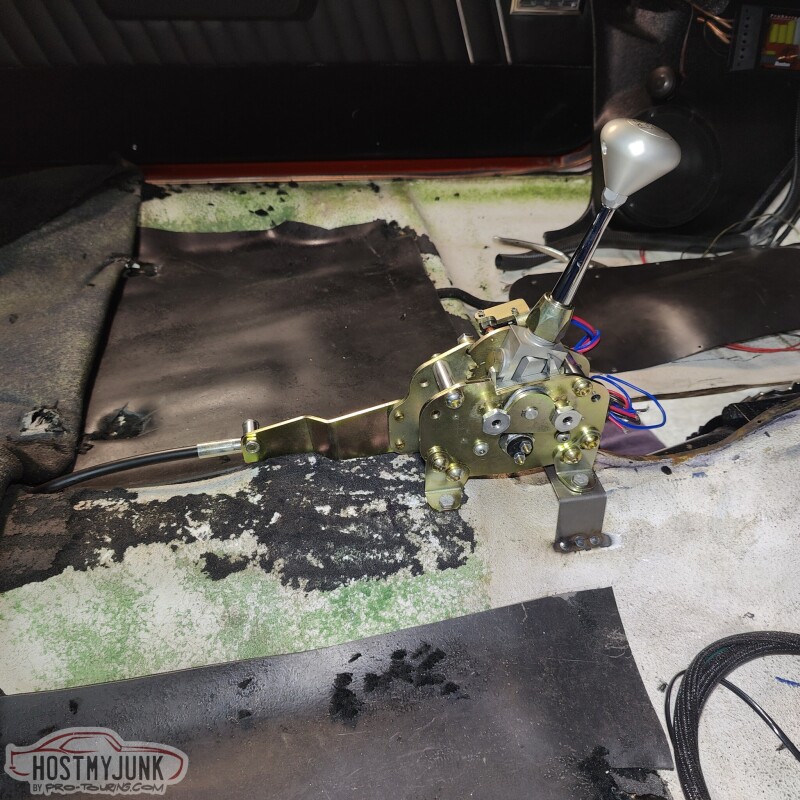
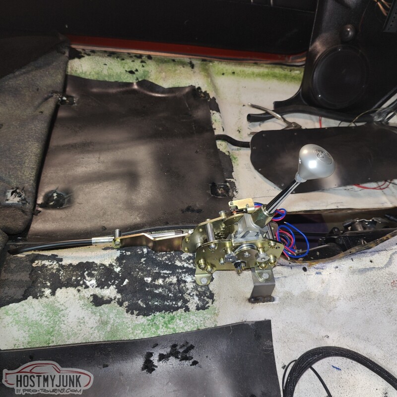
The shifter feels pretty good, but there are some minor adjustments that need to be made still.
Jimbo, I hope these welds meet your standards...
Andrew
So it was time to put the big boy pants on and poke some holes to mount the shifter. I positioned it in such a way that with the shifter in Drive, I could, very naturally, put my hand on the shift level and slide it to the right and use the forward and backwards tap shift feature.
I drilled the first hole and shockingly it lined up perfectly where I intended it to go. I mounted the shifter and marked the other hole.
I used nut-serts (riv-nuts) inside the hole and temporarily mounted the shifter.
I did a little more measuring and drilled a hole in the floor for the shifter cable. ICT Billet posted a teaser on their Instagram about their new shift cable pass-through and I have been bugging them about it for weeks. I am hoping it will be available soon so I can use it to seal the hole.
For the front of the shifter, Vic whipped up a simple bracket and we (yes, I welded one side and he the other...thanks you...) welded it to the floor.
The shifter feels pretty good, but there are some minor adjustments that need to be made still.
Jimbo, I hope these welds meet your standards...
Andrew
02-05-2023, 09:22 PM
#635
TECH Senior Member
Thread Starter
iTrader: (7)
My friend Blake designed and 3D priced a cover the the boost solenoids.
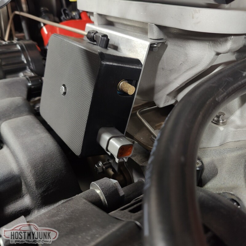
He included a cut-out on the side so that I can mount a Deutsch 4 connector bulkhead fitting, instead of the two connectors that were on the solenoids before.
Both Vic and I liked the raw 3D printed look of the sides, but the top was not as pretty. So Vic applied some vinyl to the top.
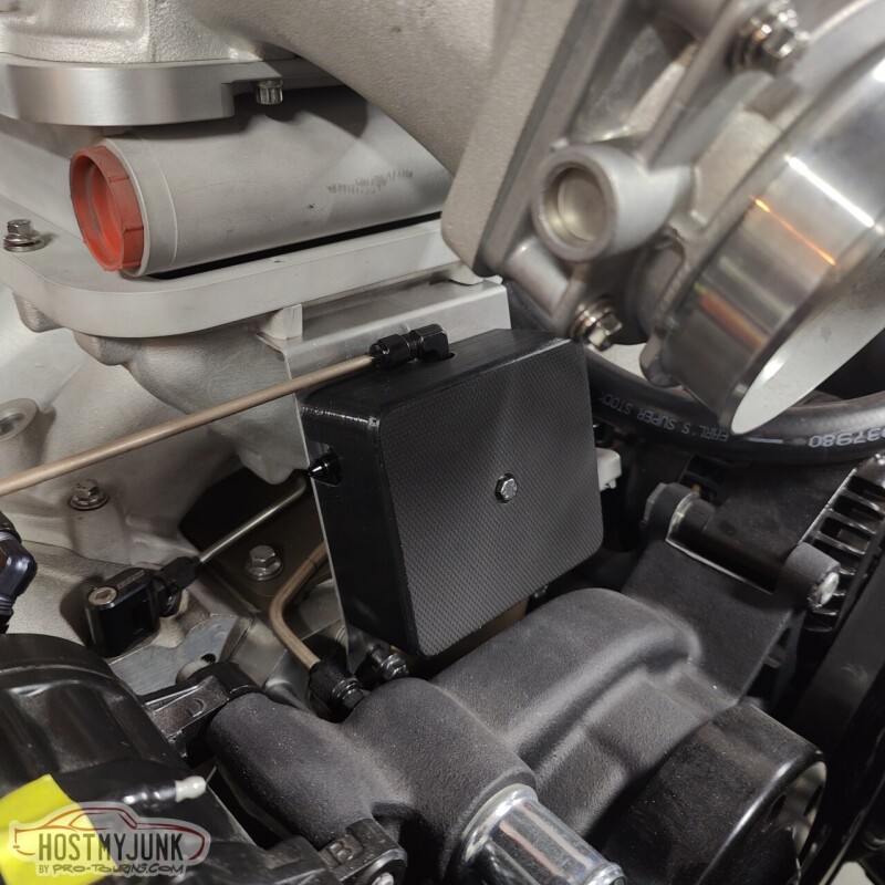
The mounting plate itself is pretty thin, so in order to tap a hole for the hold down bolt, I drilled a small hole and used a punch to gradually enlarge the hole. This folds the soft aluminum out and gives more material to tap, making it as good as a captive nut.
I also made the hose that gos from the fill tank to the top of the heat exchanger.
Hear are the two heat exchanger lines where they slip between the core support and the radiator.
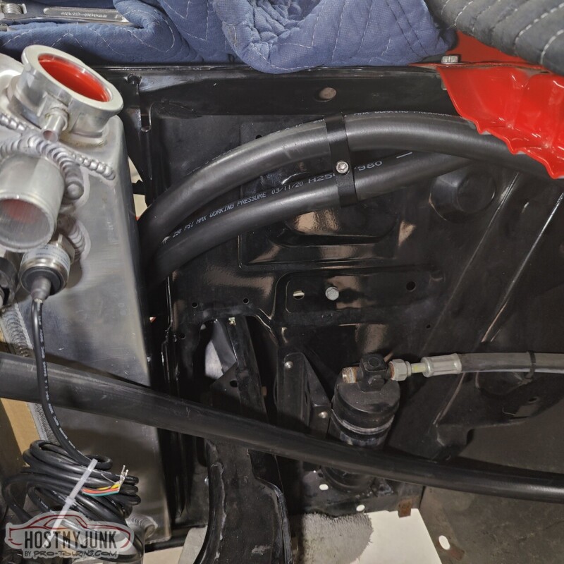
The hose from the bottom of the heat exchanger loops towards the fender, then comes over the fan, and then down into the top of the pump.
I also took the turbo off so that I could rattle can the turbo support bracket.
Andrew
He included a cut-out on the side so that I can mount a Deutsch 4 connector bulkhead fitting, instead of the two connectors that were on the solenoids before.
Both Vic and I liked the raw 3D printed look of the sides, but the top was not as pretty. So Vic applied some vinyl to the top.
The mounting plate itself is pretty thin, so in order to tap a hole for the hold down bolt, I drilled a small hole and used a punch to gradually enlarge the hole. This folds the soft aluminum out and gives more material to tap, making it as good as a captive nut.
I also made the hose that gos from the fill tank to the top of the heat exchanger.
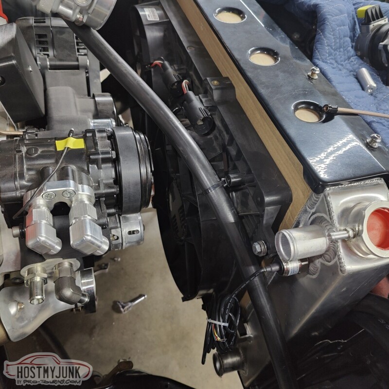
Hear are the two heat exchanger lines where they slip between the core support and the radiator.
The hose from the bottom of the heat exchanger loops towards the fender, then comes over the fan, and then down into the top of the pump.
I also took the turbo off so that I could rattle can the turbo support bracket.
Andrew
The following 2 users liked this post by Project GatTagO:
2ToeRacing (07-16-2023), 93Polo (02-08-2023)
02-05-2023, 09:28 PM
#636
TECH Senior Member
SUCH a clean build!!
The following 2 users liked this post by G Atsma:
Jimbo1367 (02-09-2023), Project GatTagO (02-06-2023)
02-08-2023, 09:26 PM
#637
TECH Senior Member
Thread Starter
iTrader: (7)
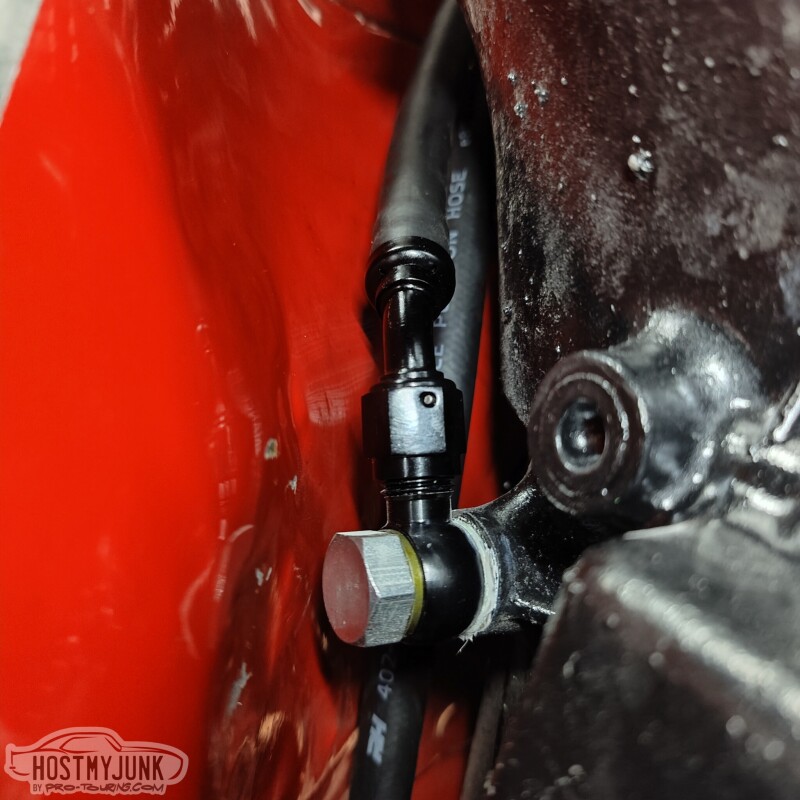
Today was another plumbing day. This time it was time to plumb the transmission cooler. Here is a little tip when working with push-lock style hose.
Add a union to the fitting and snug it down. This does two things:
1. If using a 45 or 90 degree fitting it keeps the nipple from trying to move around.
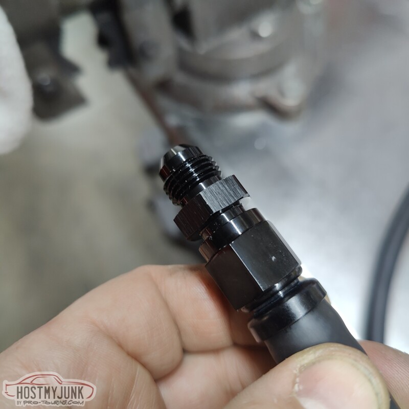
2. When putting the fitting in the vise to hold it, it keeps the the nut from crushing and becoming out of round.
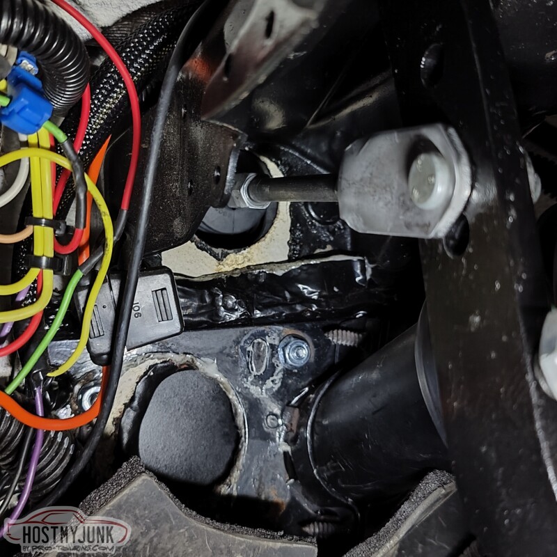
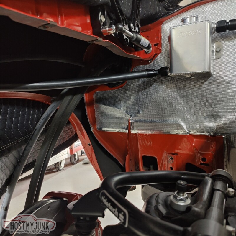
This is the rear fitting on the transmission. The picture actually makes it look like there is a lot of clearance, but in reality it is very tight.
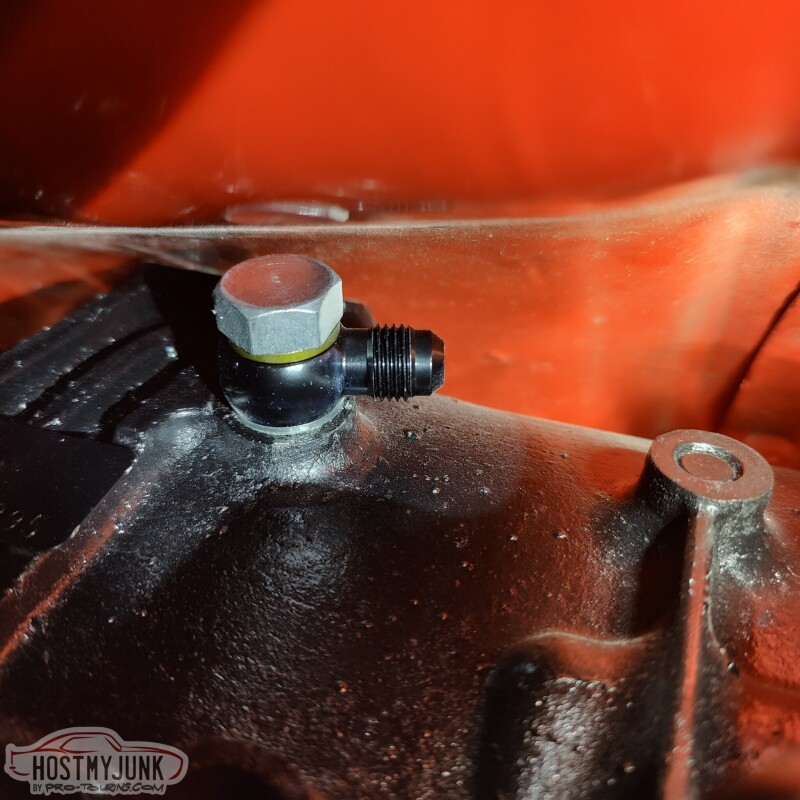
I managed to get the hose end started, but I will probably have to get creative with getting it tight. I think a Crow's foot should get it done.
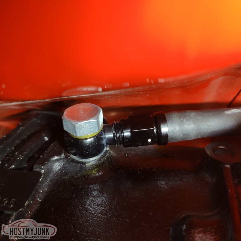
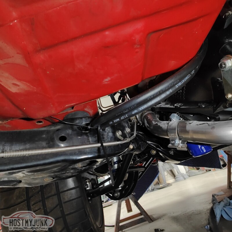
The front port wasn't too bad. I used a 45 degree fitting on this hose. Removing the trans dipstick made access easier.
The hoses make a gently sweep over the bell housing area of the transmission, over to the driver's side, where they slip into a slot in the frame. This slot is where the factory hard lines were routed through the frame and out the front crossmember, by the steering box.
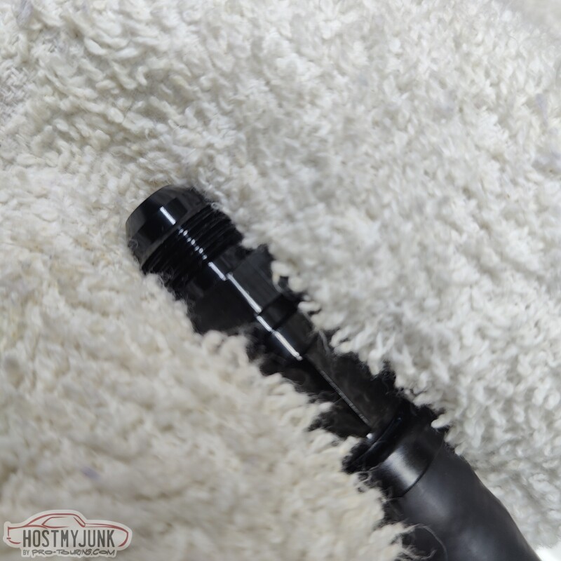
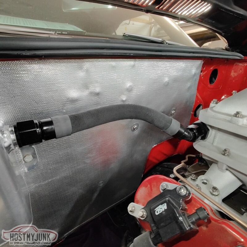
I also experimented with some covering material for the intercooler plumbing. This is a fabric heat shrink material.
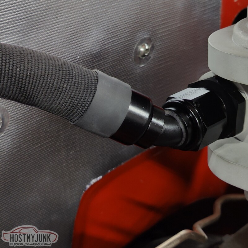
The ends are finished with heat shrink. This is a close-up to show the pattern and texture.
Andrew
Add a union to the fitting and snug it down. This does two things:
1. If using a 45 or 90 degree fitting it keeps the nipple from trying to move around.
2. When putting the fitting in the vise to hold it, it keeps the the nut from crushing and becoming out of round.
This is the rear fitting on the transmission. The picture actually makes it look like there is a lot of clearance, but in reality it is very tight.
I managed to get the hose end started, but I will probably have to get creative with getting it tight. I think a Crow's foot should get it done.
The front port wasn't too bad. I used a 45 degree fitting on this hose. Removing the trans dipstick made access easier.
The hoses make a gently sweep over the bell housing area of the transmission, over to the driver's side, where they slip into a slot in the frame. This slot is where the factory hard lines were routed through the frame and out the front crossmember, by the steering box.
I also experimented with some covering material for the intercooler plumbing. This is a fabric heat shrink material.
The ends are finished with heat shrink. This is a close-up to show the pattern and texture.
Andrew
The following users liked this post:
nleming (02-11-2023)
02-09-2023, 04:57 AM
#639
Man��I really like all of the nifty tricks Andrew does to make everything clean and professional. Great job
The following users liked this post:
Project GatTagO (02-09-2023)
