

Wiring upgrade for older cars pics and ideas.
 04-09-2006, 02:15 AM
#1
this is a re-post, I initially put it into the sticky thread, but nobody reads those, so thought this could stir up some discussion/brainstorming, whatev.
ahem.
Stu Cool sent me a link about wiring, this pertains to pretty much all older cars, and has some GREAT ideas. Using the diagrams, I designed my own wiring upgrade for my car, and built a relay board at the front of my car to improve the lighting capabilities. I HIGHLY reccomend this, at least take the time to read it. I'd never really done any wiring in my life, but I went to Autozone, bought some relays, some wire, busted out the crimping tools and some spade connectors, and went crazy.
http://www.madelectrical.com/electrical-tech.shtml
here's what I came up with..
I bought some 1"x1" aluminum angle from lowes, cut about 9" off it, polished it to a mirror shine, and proceeded to make it into my relay board. I used aluminum because if taken care of, it doesnt corrode badly, conducts well, and is lightweight, and also because aluminum's easy to polish.
1. First, I chopped the mounting tabs off the relays, (baja style 12v 30amp relays from Autozone, about 6 dollars each. One is needed for high-beam, one for low. I also got two for fans, and one for horn. After scuffing both the backs of the relays, and the inside of the aluminum, I epoxy'd them in a line.
2. I drilled a hole, threaded a bolt through to connect all of the grounds of the relays onto a single post, to make it clean, and simple.
3. I went to radioshack, bought a bus bar terminal thing, and connected all the positive connections to this. The bus bar will be fed by an 8 gauge wire linked to my central power hub (behind the firewall).
4. I epoxy'd the bus bar with enough room to spare from the relays, and then put a small, self-tapping screw through to hold it securely.
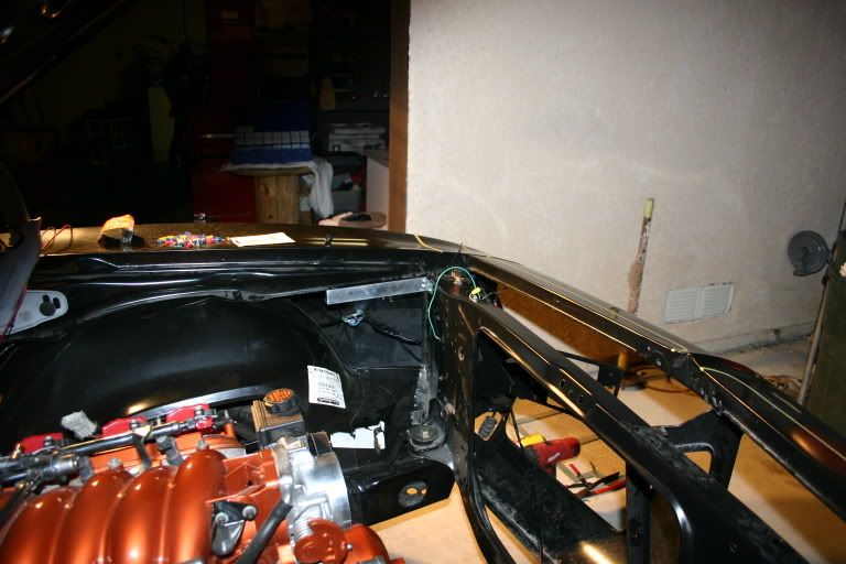
5. I went into my wiring harness, at the core support (I had already hidden my lighting harness between the inner/outer fenders, it was invisible... and cut the high-beam and low-beam wires, adding spade connectors to them, and plugging them into the relay. The part that went to the firewall was used as the "turn-on" signal, and the lights were then powered by the remaining terminal.
6. I then mounted my aluminum bracket and its relays off to the side of the core support, no wires are visible anymore, and headlights are extremely bright, once I got the grounds good. They're much more noticeably brighter than before, i'm very happy that I did this mod.
Reading the tech articles on that site are the way to go, if just to learn something new.
here's some pics of my recent electronic adventure..
my circuit board..
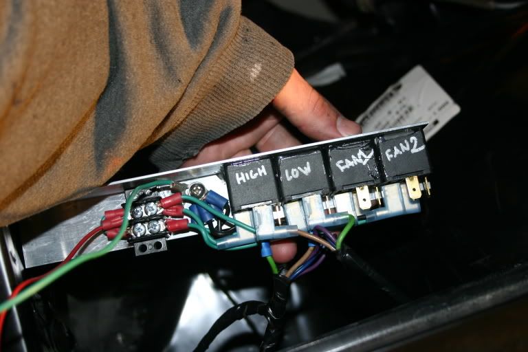
note that green are +12v, (i didnt have red) and black are ground.
where I put them.. (the closer to the draw, in this case the lights, the less voltage drop you've got, so the lights are brighter, and this puts NO strain on the car's electronics inside, so no dimming dash lights, etc etc..) It's also easier on the wiring, I think a big current draw through a long length of small wire is more prone to a fire.. I'm no pro, (this is my first wiring thing,) but that's what i've gathered.
anyways.. they're tucked away out of sight.. (ignore the jumper wires, they're just to test it, none will be visible once it's operational...
questions or comments are welcome!
oh, and the final result..
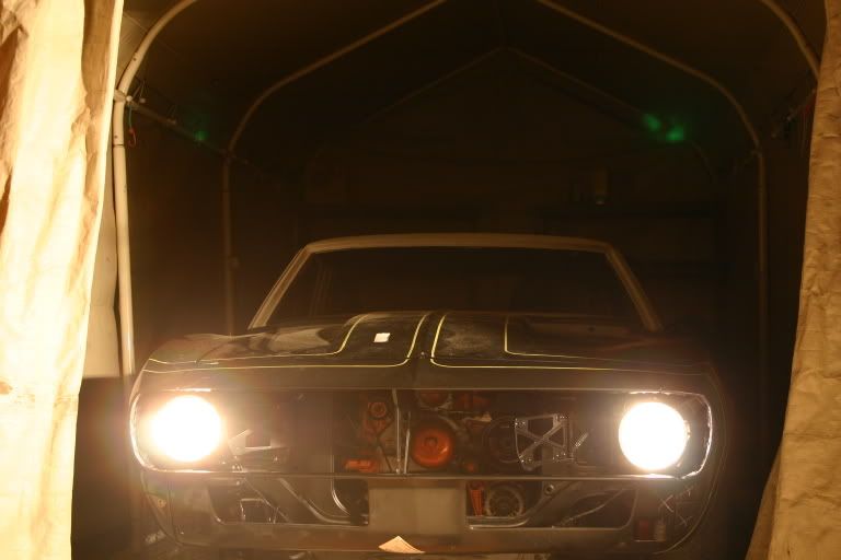
high beam goodness.

olly
ahem.
Stu Cool sent me a link about wiring, this pertains to pretty much all older cars, and has some GREAT ideas. Using the diagrams, I designed my own wiring upgrade for my car, and built a relay board at the front of my car to improve the lighting capabilities. I HIGHLY reccomend this, at least take the time to read it. I'd never really done any wiring in my life, but I went to Autozone, bought some relays, some wire, busted out the crimping tools and some spade connectors, and went crazy.
http://www.madelectrical.com/electrical-tech.shtml
here's what I came up with..
I bought some 1"x1" aluminum angle from lowes, cut about 9" off it, polished it to a mirror shine, and proceeded to make it into my relay board. I used aluminum because if taken care of, it doesnt corrode badly, conducts well, and is lightweight, and also because aluminum's easy to polish.
1. First, I chopped the mounting tabs off the relays, (baja style 12v 30amp relays from Autozone, about 6 dollars each. One is needed for high-beam, one for low. I also got two for fans, and one for horn. After scuffing both the backs of the relays, and the inside of the aluminum, I epoxy'd them in a line.
2. I drilled a hole, threaded a bolt through to connect all of the grounds of the relays onto a single post, to make it clean, and simple.
3. I went to radioshack, bought a bus bar terminal thing, and connected all the positive connections to this. The bus bar will be fed by an 8 gauge wire linked to my central power hub (behind the firewall).
4. I epoxy'd the bus bar with enough room to spare from the relays, and then put a small, self-tapping screw through to hold it securely.
5. I went into my wiring harness, at the core support (I had already hidden my lighting harness between the inner/outer fenders, it was invisible... and cut the high-beam and low-beam wires, adding spade connectors to them, and plugging them into the relay. The part that went to the firewall was used as the "turn-on" signal, and the lights were then powered by the remaining terminal.
6. I then mounted my aluminum bracket and its relays off to the side of the core support, no wires are visible anymore, and headlights are extremely bright, once I got the grounds good. They're much more noticeably brighter than before, i'm very happy that I did this mod.
Reading the tech articles on that site are the way to go, if just to learn something new.
here's some pics of my recent electronic adventure..
my circuit board..
note that green are +12v, (i didnt have red) and black are ground.
where I put them.. (the closer to the draw, in this case the lights, the less voltage drop you've got, so the lights are brighter, and this puts NO strain on the car's electronics inside, so no dimming dash lights, etc etc..) It's also easier on the wiring, I think a big current draw through a long length of small wire is more prone to a fire.. I'm no pro, (this is my first wiring thing,) but that's what i've gathered.
anyways.. they're tucked away out of sight.. (ignore the jumper wires, they're just to test it, none will be visible once it's operational...
questions or comments are welcome!
oh, and the final result..
high beam goodness.
olly
Last edited by 67RSCamaroVette; 04-09-2006 at 02:32 AM.
 04-09-2006, 07:32 AM
#2
Teching In

Join Date: Feb 2006
Location: South Florida
Posts: 24
Likes: 0
Received 0 Likes
on
0 Posts
Neat stuff. Thanks for sharing. My only question is why cement the relays to the aluminum bar? Wouldn't they be easier to service or repair if they used the existing tab and were attatched using fasteners of some type? They relay deal makes sense. Any of us who have wired drivng lights and other accessories "straight" can probably testify that they didn't last as long as you thought they should! Relays will really help that situation!
04-09-2006, 09:34 AM
#3
Olly, Good work, I think you will like the results. Glad my suggestion was helpfull. I did pretty much the same thing, except instead of using an aluminum bar, I found an old metal first aid kit to put everything in. I mounted it up under my fenderwell behind the driver's head light. To keep the relays in place in the box, I used Velcro. That way they will be easy to change or move out of the way if needed. I documented this project on my Yahoo Photos page here:
http://pg.photos.yahoo.com/ph/pat_di...ling/my_photos
This was all prior to my current LS1 swap project, but so far everything wroks including the remote solenoid.
I've attached a couple pictures of the relay box.
Pat
http://pg.photos.yahoo.com/ph/pat_di...ling/my_photos
This was all prior to my current LS1 swap project, but so far everything wroks including the remote solenoid.
I've attached a couple pictures of the relay box.
Pat
Last edited by Stu Cool; 04-09-2006 at 09:45 AM.
04-09-2006, 09:50 AM
#4
nice relay setup..you might wanna mount the relay in such a way that you can replace them. I mounted mine in the same location but directly to the body...that way if one goes out, it will be easy to replace. I am thinking about mounting the relay sockets onto a plexi glass plate and boxing it like they do in newer cars....+ that would look better than what I have now(see pic below)
I have also been doing something similar. There is endless ways to improve your old car with relays. I talked to Mark....the owner of Madelectrical and he was very helpful.
I set out to completely rewire my car with a painless performance harness and add a few touches. My original harness had some burned out wires so I figured I was not going to risk having my car burn up coz of some electrical fire
Besides relays for the headlights and fans, I am using them for the following functions
1.anti run on relay
2.Security switch..the relays provides the ground...car will not start with this switch off
3.Headlight on warning buzzer.....I am really bad at leaving my headlights on...did twice last summer and both times my batt died.
4. Fan mulfunction relay.....if for some reason the primary fan stops running with the car on, this relay will turn on a flashing red LED on my console.
5. Amp turn on. I will be running dua amps...this relay will take the load off the receiver.
Marks website is very informative....he has schematics showing how to upgrade the power distribution in your old car.
Since I am using the painless harness, I made up some wiring diagrams to help me before I start. I started a few days ago.Here are some pics.
Painless harness


Headlight and Fans relays.

Wiring Diagrams. I still have to fix some errors I found in my diagrams and rearrange a few circuits
Can you tell I have alot of time on my hands?


I have also been doing something similar. There is endless ways to improve your old car with relays. I talked to Mark....the owner of Madelectrical and he was very helpful.
I set out to completely rewire my car with a painless performance harness and add a few touches. My original harness had some burned out wires so I figured I was not going to risk having my car burn up coz of some electrical fire
Besides relays for the headlights and fans, I am using them for the following functions
1.anti run on relay
2.Security switch..the relays provides the ground...car will not start with this switch off
3.Headlight on warning buzzer.....I am really bad at leaving my headlights on...did twice last summer and both times my batt died.
4. Fan mulfunction relay.....if for some reason the primary fan stops running with the car on, this relay will turn on a flashing red LED on my console.
5. Amp turn on. I will be running dua amps...this relay will take the load off the receiver.
Marks website is very informative....he has schematics showing how to upgrade the power distribution in your old car.
Since I am using the painless harness, I made up some wiring diagrams to help me before I start. I started a few days ago.Here are some pics.
Painless harness
Headlight and Fans relays.
Wiring Diagrams. I still have to fix some errors I found in my diagrams and rearrange a few circuits
Can you tell I have alot of time on my hands?
 04-09-2006, 01:10 PM
#6
I thought about that, too. If one goes, I'll just pop them off and use some double sided velcro on the strip to keep them all on. I thought about that AFTER the epoxy had cured, haha. Thanks for replies, schitzo, a blueprint of your whole car's electrical system is awesome, i've been squinting over a little 4x4" wiring diagram for the front of my car to get the pinouts, tracing the little lines with a pencil. what you're doing is a great idea.. my dad designed communications systems, and electrical, and his "plans" looked just like those, with special symbols and stuff.. Are you in any kind of field like that?
04-09-2006, 02:01 PM
#7
I guess that should work until you can change it. I wanted to do this right the first time so I want to be sure I know exactly what I am doing before I start hooking stuff up and cutting wires
nope.......I am into drugs......phamarcy student
Originally Posted by 67RSCamaroVette
. Are you in any kind of field like that?
Trending Topics
04-09-2006, 07:09 PM
#8

those relays are WAY to small for an electric fan. you better run a LED back to the inside of your car from the hot side of the fan relay. that will let you know when it burns out.
i used the factory relays from the LS1 harness for my fans, horns, lights, etc.
i used the factory relays from the LS1 harness for my fans, horns, lights, etc.
04-09-2006, 07:35 PM
#9
Originally Posted by SatisTraction
those relays are WAY to small for an electric fan. you better run a LED back to the inside of your car from the hot side of the fan relay. that will let you know when it burns out.
i used the factory relays from the LS1 harness for my fans, horns, lights, etc.
i used the factory relays from the LS1 harness for my fans, horns, lights, etc.
what are the factory fans relays rated at?
It is also a good idea to install a diode btw the fan leads....this helps prevent the relay from being destroyed by feedback from the fan when you shut of the car.
04-09-2006, 08:09 PM
#11
TECH Fanatic
iTrader: (9)
Join Date: Mar 2004
Location: CANADA!
Posts: 1,347
Likes: 0
Received 0 Likes
on
0 Posts

Originally Posted by Schitzo
what are the factory fans relays rated at?
-Matt
04-09-2006, 08:30 PM
#13
TECH Fanatic
iTrader: (9)
Join Date: Mar 2004
Location: CANADA!
Posts: 1,347
Likes: 0
Received 0 Likes
on
0 Posts
Originally Posted by SatisTraction
i am 99% sure you need a 75 amp relay for a mark VIII fan.
-Matt
04-09-2006, 08:48 PM
#15
also.....do the LS1 fans both come on at the same time or does the second one come on at a certain temp?
Olly do a search online and you can find those high amp relays......I have a link somewhere on my computer I am just having a hard time finding it right now.
Olly do a search online and you can find those high amp relays......I have a link somewhere on my computer I am just having a hard time finding it right now.
04-09-2006, 09:26 PM
#16
I am running two 30 Amp relays in parallel for each fan. I believe I got that idea in a diagram from Mad Electrical. Not sure if it was on their web site or in one of the books I got from them. The power going to each relay has a fusible link soldered in for overload protection. I am running aftermarket SPAL fans this way for over a year without problems.
Pat
Pat
04-09-2006, 11:24 PM
#18
TECH Apprentice
iTrader: (1)
Join Date: Mar 2004
Location: Newport, NC
Posts: 306
Likes: 0
Received 0 Likes
on
0 Posts
Ok, call me niave, but I have been thinking of putting an LS1 and MN6 in a 1969 Firebird. But, I thought it would be easiet to just use the newer donor car's entire wiring harnes (front to rear) and just label it as I removed it, and then splice it in where I needed to. Mind you, I thought it would be easier to use the donor car's gauges, ac control, etc. It just seemed logical. Or is that just too easy?
04-09-2006, 11:29 PM
#19
It could be done. My LS1 wiring harness was butchered beyond belief, I had no donor car, and the '67's harness was shipshape, except for its engineering downfalls. That's what the thread's for.. the best way to upgrade the existing wiring using new relays/solenoids... Personally if I was going to re-wire the whole car, i'd do what Schitzo is doing and go for Painless's XX circuit hot rod harness.
olly
olly
04-10-2006, 12:08 AM
#20
Olly,
Go back to the Mad Electrical site and check the link below. Scroll down to where it talks about fans. He explains why he recommends using two 30 amp relays in parallel instead of one big relay.
http://www.madelectrical.com/catalog/rly-1.shtml
Hope this helps. If you have a mind to, give Mark a call he is very helpful and will take time to explanin things you may have questions about.
Pat