
Homemade VATS bypass box...


 07-28-2008, 05:04 PM
#22
Teching In

Join Date: Jul 2008
Posts: 2
Likes: 0
Received 0 Likes
on
0 Posts

Paul... Not sure about your starting issue. Ive heard that the security light comes on if there are issues. But I wouldnt know. This info was more for drivetrains that were no longer in 4th gen bodies. The DIY stand alone harness guys. However...Im sure there is a way to check to see if you problem is VATS related or not. And just to clarify...most of the time your car will start even if VATS is acting up. But it will start up and shut off. If its a problem with the resistor in the key...I dont know that it will even crank. In that case, you could try bypassing the resistor with circuit resistors...there aer bunch of threads on how to do that.
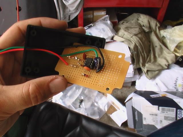
Just for fun here is a pic of my masterpiece...not! haha. I soldered this together in like 20 minutes so its not the best. But it proved my car would run, so it served its purpose.
Justin
Just for fun here is a pic of my masterpiece...not! haha. I soldered this together in like 20 minutes so its not the best. But it proved my car would run, so it served its purpose.
Justin
Could you grab a picture of the bottom on this bypass module?
I just made an attempt.. I guess i have no done it correctly..
Now trying without the bypass module.. I got a reading directly from my key. It showed 9.5ohm. Now i also purchased a 10K ohm resistor from radi oshack. That got the car started.. however it sounded like a V8 with a cam for high end lol... barely running at 500rpm.. and it eventually died. After the attempts with the bypass module.. i tried the 10k OHM again. it did not work at all.
I dont have a multi meter myself. I used one at radio shack for the reading on my key. I do not know of anyone within 150 miles that owns a HPT.
Any help to get my car running again would be apreciated.
I beleive it has passkeyII. Its a 2000 Grand Prix Motor, with a 1998 Monte carlo wiring harness. All inside a 1993 Grand Prix Body.
08-03-2008, 09:56 PM
#23

I got your PMs... If I can find that box, Ill snap a pic for ya. That box has been long gone from the car. I purchased a pre-made unit from ebay that I was using since. And now that my car seems to run without the module.....so I dont even know where the little one is. haha.
But if I can find it, Ill take a pic. Its pretty hacked together....but it worked. This thread has all the links and info that I used to build it. If you cant seem to get yours to work...you can always grab one off ebay. They arent very expensive and are in a neat little package.
J.
But if I can find it, Ill take a pic. Its pretty hacked together....but it worked. This thread has all the links and info that I used to build it. If you cant seem to get yours to work...you can always grab one off ebay. They arent very expensive and are in a neat little package.
J.
04-27-2010, 10:46 PM
#24
Teching In

Join Date: Apr 2010
Posts: 2
Likes: 0
Received 0 Likes
on
0 Posts
hello yall, i know im diggin up an old post but, and this may not be the best site for me, but i have a 1995 camaro v6 3.4 L . ive had the car about 2 days and am already starting to get frustrated lol. I know its the vats. I built a vats bypass module today using alot of info from this thread.. which i do thank yall for. I have my 3 wires on the bypass module, i know one is hot and one is ground and one is the fuel enable signal, fricken prblem is that i dont know which wire on my car is the fuel enable wire, and i cant dig up anything to let me know, seen lots of different options but havent seen mine. I believe the bcm, or tdm or whatever it is, is the silver box i have located and dropped from under the passenger side dash near the starter relay under the glove compartment. The plug on the assumed bcm is a yellow plug with 2 rows of 12 prongs. I have no clue which wire is the fuel enable wire, and well, i have to get fuel to make the m effer run. If anyone has any insight please let me know. I have been reading all day. I built the bypass module, and i just need to know one lil fricken wire.... thanks alot. KC
04-28-2010, 06:17 AM
#25

Its in the PCM, not the BCM. Stay away from yellow harnesses and connectors. Those are for airbag systems
Find a pinout for your V6 PCM and find the wire. V8 pinouts will not work as they use a different PCM. A service manual, ALLData and 60degreeV6.com will have the info you need
Find a pinout for your V6 PCM and find the wire. V8 pinouts will not work as they use a different PCM. A service manual, ALLData and 60degreeV6.com will have the info you need
04-28-2010, 05:04 PM
#26
Teching In
Join Date: Apr 2010
Posts: 2
Likes: 0
Received 0 Likes
on
0 Posts
im on the v6 forum now too, still no luck. Its not the first time this has happened i know. I know yall basically use this for putting ls1 and such in cars like mine... but still shouldnt i hook the by module up the same? is the pcm the computer under the hood? anyone know which wire gong it to it would be the fuel enable wire? c'mon
10-16-2010, 07:53 AM
#27
Teching In

Join Date: Oct 2010
Posts: 1
Likes: 0
Received 0 Likes
on
0 Posts
Hi guys.
Was getting ready to shop for parts and try the by-pass and remembered that the early vats was a 30hz signal. I'm assuming that my 92 camaro is the 30hz ? If so what components will I need to change or add ? I'm not an electronics expert (duh), but I really need to get the car running again and can't afford Summit's price since having to rebuild the house. The problem with the vats may just be something simple that the tornado last year added to, but I really want the VATS gone anyway.
Any help is greatly appreciated.

 05-06-2013, 11:04 PM
#31
Registered User

Join Date: May 2013
Posts: 1
Likes: 0
Received 0 Likes
on
0 Posts
i just sign on to this site . can you help me? i just got a 87 vette with no keys. today i got everthing that i need to make homemade vats bypass box and dont know where to start pin 1 pin 2 have no clue need picture ,need help.will this even work on a 87 corvette?
05-07-2013, 07:21 AM
#32
Sorry, this will not work for your 87 corvette TPI system
It along with 3rd gen TPI systems uses Passkey I VATS while late LT1 and LSx engines use Passkey II systems
If you are putting a later engine into your corvette, then yes it will work, but you must deal with the remnants of the original VATS system. For 3rd gens the starter enable relay is all that remains. Im not sure on corvettes
10-15-2013, 12:10 PM
#35
I got everything I needed from a quick trip to radio shack. They had it all. The enclosure isnt THAT important. You can use anything. Heck..put it in an insulated altoids container haha. If you dont want to remove it for security, you could leave it out of an enclosure really. You could wrap it in some electrical tape and mount it to the PCM body, or under the dash.
But check radio shack...they should have one for you. Mine was the enclosure and the properly sized PC board all together.
J.
But check radio shack...they should have one for you. Mine was the enclosure and the properly sized PC board all together.
J.
04-06-2014, 09:39 PM
#36
Teching In

Join Date: Apr 2014
Posts: 1
Likes: 0
Received 0 Likes
on
0 Posts
Hey all. I have a handful of people asking me about the vats bypass box that I made...so I thought I would make a new post about it. I did a lot of searching, and it took me quite awhile to find info on it. Actually most of the info I found by using google not LS1tech. I realized that with LS1edit and HPTuners and maybe other software floating around, most people just get the VATS eliminated. I thought I did already but aparently not. So this is to help those people who are at the point where they want to run their car, but get stuck with vats.
This is a cheap project. Even if you dont have a soldering iron..radio shack has a good powered iron there for $7...cant beat that. Im going to post a couple sites that I found info on...then what I learned while building mine. I dont have any pictures of mine right now...but I can get them.
Here is the first site. This site contains the list of parts taht you will need. Write them down exactly as they are in the list...if you cant find the parts at radio shack...ask for help. They have them all.
http://temp.corvetteforum.net/c3/70lt1/vats.shtml
This site also references the site above..but provides a different configuration for how the parts are arranged. I wish I built mine like this...this makes it into a "security key" type thing. Im actually thinking about leaving the vats programmed in, and using it as an added security measure.
http://www.corvetteforum.net/c3/gameshowbob/swap6.html
Here is a link to the schematic for the box...just for quicker reference.
http://i57.photobucket.com/albums/g2...tschematic.jpg
The problem I had was when i put it together with the ground wire in the location shown, it didnt work. It did nothing. Car still acted the same. What I ended up doing is moving the ground wire to the pin on the 555timer that was for "ground". It shows you which pin that is on the back of the package. I cant remember which one it is right now...but I think its either 1 or 2... When I get home today Ill confirm it and update this post.
The box I made isnt pretty. I got the project box/circuit board combo from radio shack...so its bigger than the ones the other guys built. I only built it to make sure that was my problem. After I found out that it would run...I bought a box from baker electronics. Its small and I trust it alittle more as I built my box in a big hurry. But if you take you time, and make all your connections good, you can make it just as nice.
If you have any other questions feel free to ask... if you need help with soldering or building the circuit...shoot me a PM and Ill try to help you out.
Justin
05-25-2016, 09:17 PM
#37
Registered User

Join Date: May 2016
Posts: 1
Likes: 0
Received 0 Likes
on
0 Posts
Hi i have a 1994 cadillac fleetwood with a lt1 and i got a bypass but having a hard time trying to figure out where i hook it up thanks i really would appreciate any help
01-25-2017, 05:40 AM
#38
Registered User

Join Date: Jan 2017
Posts: 1
Likes: 0
Received 0 Likes
on
0 Posts
Hola, saludos para todos. ghettocruiser yo hice la simulaci�n con livewire, y quedo asi puede decirme si esta bien, y tuve que cambiar el valor de la resistencia de 100 ohm a 500 ohm en la entrada porque en el simulador explota.
02-20-2022, 02:16 PM
#39
Registered User

Join Date: Feb 2022
Posts: 1
Likes: 0
Received 0 Likes
on
0 Posts
Hey all. I have a handful of people asking me about the vats bypass box that I made...so I thought I would make a new post about it. I did a lot of searching, and it took me quite awhile to find info on it. Actually most of the info I found by using google not LS1tech. I realized that with LS1edit and HPTuners and maybe other software floating around, most people just get the VATS eliminated. I thought I did already but aparently not. So this is to help those people who are at the point where they want to run their car, but get stuck with vats.
This is a cheap project. Even if you dont have a soldering iron..radio shack has a good powered iron there for $7...cant beat that. Im going to post a couple sites that I found info on...then what I learned while building mine. I dont have any pictures of mine right now...but I can get them.
Here is the first site. This site contains the list of parts taht you will need. Write them down exactly as they are in the list...if you cant find the parts at radio shack...ask for help. They have them all.
http://temp.corvetteforum.net/c3/70lt1/vats.shtml
This site also references the site above..but provides a different configuration for how the parts are arranged. I wish I built mine like this...this makes it into a "security key" type thing. Im actually thinking about leaving the vats programmed in, and using it as an added security measure.
http://www.corvetteforum.net/c3/gameshowbob/swap6.html
Here is a link to the schematic for the box...just for quicker reference.
http://i57.photobucket.com/albums/g2...tschematic.jpg
The problem I had was when i put it together with the ground wire in the location shown, it didnt work. It did nothing. Car still acted the same. What I ended up doing is moving the ground wire to the pin on the 555timer that was for "ground". It shows you which pin that is on the back of the package. I cant remember which one it is right now...but I think its either 1 or 2... When I get home today Ill confirm it and update this post.
The box I made isnt pretty. I got the project box/circuit board combo from radio shack...so its bigger than the ones the other guys built. I only built it to make sure that was my problem. After I found out that it would run...I bought a box from baker electronics. Its small and I trust it alittle more as I built my box in a big hurry. But if you take you time, and make all your connections good, you can make it just as nice.
If you have any other questions feel free to ask... if you need help with soldering or building the circuit...shoot me a PM and Ill try to help you out.
Justin
This is a cheap project. Even if you dont have a soldering iron..radio shack has a good powered iron there for $7...cant beat that. Im going to post a couple sites that I found info on...then what I learned while building mine. I dont have any pictures of mine right now...but I can get them.
Here is the first site. This site contains the list of parts taht you will need. Write them down exactly as they are in the list...if you cant find the parts at radio shack...ask for help. They have them all.
http://temp.corvetteforum.net/c3/70lt1/vats.shtml
This site also references the site above..but provides a different configuration for how the parts are arranged. I wish I built mine like this...this makes it into a "security key" type thing. Im actually thinking about leaving the vats programmed in, and using it as an added security measure.
http://www.corvetteforum.net/c3/gameshowbob/swap6.html
Here is a link to the schematic for the box...just for quicker reference.
http://i57.photobucket.com/albums/g2...tschematic.jpg
The problem I had was when i put it together with the ground wire in the location shown, it didnt work. It did nothing. Car still acted the same. What I ended up doing is moving the ground wire to the pin on the 555timer that was for "ground". It shows you which pin that is on the back of the package. I cant remember which one it is right now...but I think its either 1 or 2... When I get home today Ill confirm it and update this post.
The box I made isnt pretty. I got the project box/circuit board combo from radio shack...so its bigger than the ones the other guys built. I only built it to make sure that was my problem. After I found out that it would run...I bought a box from baker electronics. Its small and I trust it alittle more as I built my box in a big hurry. But if you take you time, and make all your connections good, you can make it just as nice.
If you have any other questions feel free to ask... if you need help with soldering or building the circuit...shoot me a PM and Ill try to help you out.
Justin