

No Data Link


Thread Starter
On The Tree
Joined: Jul 2004
Posts: 166
Likes: 0
From: Stockholm, Sweden
I have now got my car running and have been out today driving it.
I have encountered one problem and that is that I can't get the data link to work. My EFILive Flashscan says that it can't connect to the PCM. I have voltage on pin 2 and 16 when ignition is on so I guess it should work.
I did have connection in November when I started it the first time and I did a scan of the warm up.
Anyone with any ideas?
I have the latest version of EfiLive 7.4.2
Jan

Do you have the two grounds for the data link on TWO good separate grounds?
Sometimes if you try to combine them to one ground you get issues. Also make sure that both of the grounds are really good grounds.
Justin
Sometimes if you try to combine them to one ground you get issues. Also make sure that both of the grounds are really good grounds.
Justin
Not tryin to insult your intelligence or anything... but did you wire it like this? Haha..just brainstorming with ya.
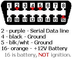
If you did, and you are getting good grounds and good 12v, then I would check the serial data line. make sure you are getting that from the right pin on the PCM...and then do a continutity check on it to make sure there are no brakes in the wire. If its the factory wire, they are pretty thin and it isnt hard to pinch them and get a crappy connection. Also, when checking the grounds for continuity, and checking the 12v feed, make sure you are checking from the "interface" side of the data connector. That way you know the pins inside the connector are good too. But thats probably what you were doing anyway...
J.

TECH Apprentice
Joined: Aug 2005
Posts: 347
Likes: 0
From: Dover Arkansas
He said he has voltage on pins 2 and 16 when ignition is on. Pin 2 should be serial data line, not voltage. You should have battery voltage at all times on pin 16, not just when ignition is on.


yea, i was going to say the same thing.
you shouldnt have voltage on two lines...
one should be a CONSTANT, always on power
the two bottom ones should be grounds.. stock, one is an engine ground, and the other is a chassis ground.... really, they can be together, as most scan tools have them connected internally anyway. just be sure its a good clean, ground.
the remaining wire is the data signal.
im searching for my picture that shows this, but search isnt cooperating with me at the moment.


