When you click on links to various merchants on this site and make a purchase, this can result in this site earning a commission. Affiliate programs and affiliations include, but are not limited to, the eBay Partner Network.
I didn't realize that lower part of the belt was so close to being inline with the tensioner pivot. You had it right all along. So if the alternator pulls 17lb your tensioner will move a notch or so from initial tension. Hopefully not a big deal. Can't wait for the twins to arrive. Be sure to give them names. My vote is Norah and Stephanie... Joe and Rosie's twin girls!
Also needed some 0.188" wall 2.0" SS304 for the wastegates to mount to, couldn't find it locally or on AceRaceParts.com, but did find it at OnlineMetals.com, which had a great selection of everything. Since I was already paying shipping for the SS304, I also got some 6" 0.100" wall 6061 aluminum that I'll turn into the surge tank for the trunk... eventually.
Is that your setup or did you just find that online? That's the first time I've seen an alternator also mounted low passenger side.. looks good! I'm assuming that's using truck accessories, which gives some room for an idler to go in front of the LQ4 waterpump. With my LS3 waterpump spaced off the block to match the LQ4 truck accessory drive location, I wouldn't have been able to put the redirect pulley in front of the waterpump, I instead had to put it below. Upside of that is it forces a bit more belt wrap around the alternator pulley.
That's my setup in the chevelle. Its very squealy. Especially right after startup , Like leaving a car cruise. Gets everyones attention. I will be very interested in your results. I know the best solution is to put the tensioner between the alt and crank pulley, But cant think of an easy/clean way to do it.
Interesting..... My reasoning for moving the alternator is aesthetics, just to get it out of the way. Distant second reason was to move it further from turbo piping heat, however I was originally planning on moving the alternator closer to the throttlebody so that even when mounted up high, the new alternator location would've been further from hot pipes than the old single turbo setup, and I never had any heat/melting issue with the old setup. So worse case scenario I can just make the new brackets that I would've needed to make anways, and move the alternator back up to high driver side.
worse case scenario I can just make the new brackets that I would've needed to make anways, and move the alternator back up to high driver side.
If you have the space, another option might be to move it back to the AC compressor position and run a dedicated 4 rib belt and tensioner for the alternator. Here's an example photo of an ac compressor/tensioner setup LINK. You might need an idler in there to get sufficient belt wrap.
I put a lot of work into getting my accessories low but to me it was absolutely worth it. It really tidies things up. You have a little more wrap on the alternator pulley than gjestico so hopefully that helps, but nothing beats real world experience. It sounds like belt sequel could be an issue.
Going to a fixed tensioner means it wont compensate as the belt stretches. I don't know if that will be a problem in normal use or if it would just need eventual adjustments.
Is there possibly space to relocate the tensioner to that same area on the main 6 rib belt (sketch attached)? Or maybe just a small idler to help improve belt wrap on the alternator pulley?
Hey Clint, neat idea.. since I don't have a two-belt-path balancer, that does create some room between the balancer and the front cover, for a tensioner to maybe fit between the alternator and balancer. I'll have a look next time I'm in the garage in a couple days.
I'm not sure if it was on here or on Instagram, but someone asked me what fender lip trimming I had to do to clear the tire at full lock, so I took some pics and a video.
Because of the camber gain from the Gulstrand mod, at full steering lock the outside tire comes closest to the trimmed fender lip around ride height, and the gap is about 3/8". Any suspension compression past that and the camber gain tucks the rim in and that gap decreases a bit to 1/4" or a little under, but then remains at that until full bump.
Because of the greater steering angle due to Ackerman, the inside tire at full lock just barely starts to rub the fender lip at full lock at ride height, and then continues to rub worse as the tire compresses. So this is okay for parking lot full lock, or hard corners as the car rolls a bit.. but the inside tire will rub the trimmed fender lip pretty bad with any compression from hard braking while at full lock. I guess I can't Gymkana this car.
The driver side, at full right steering lock...
Here is the driver side cycling thru the suspension, with a pause around half way thru at what ride height would be if there were a spring in and on the ground...
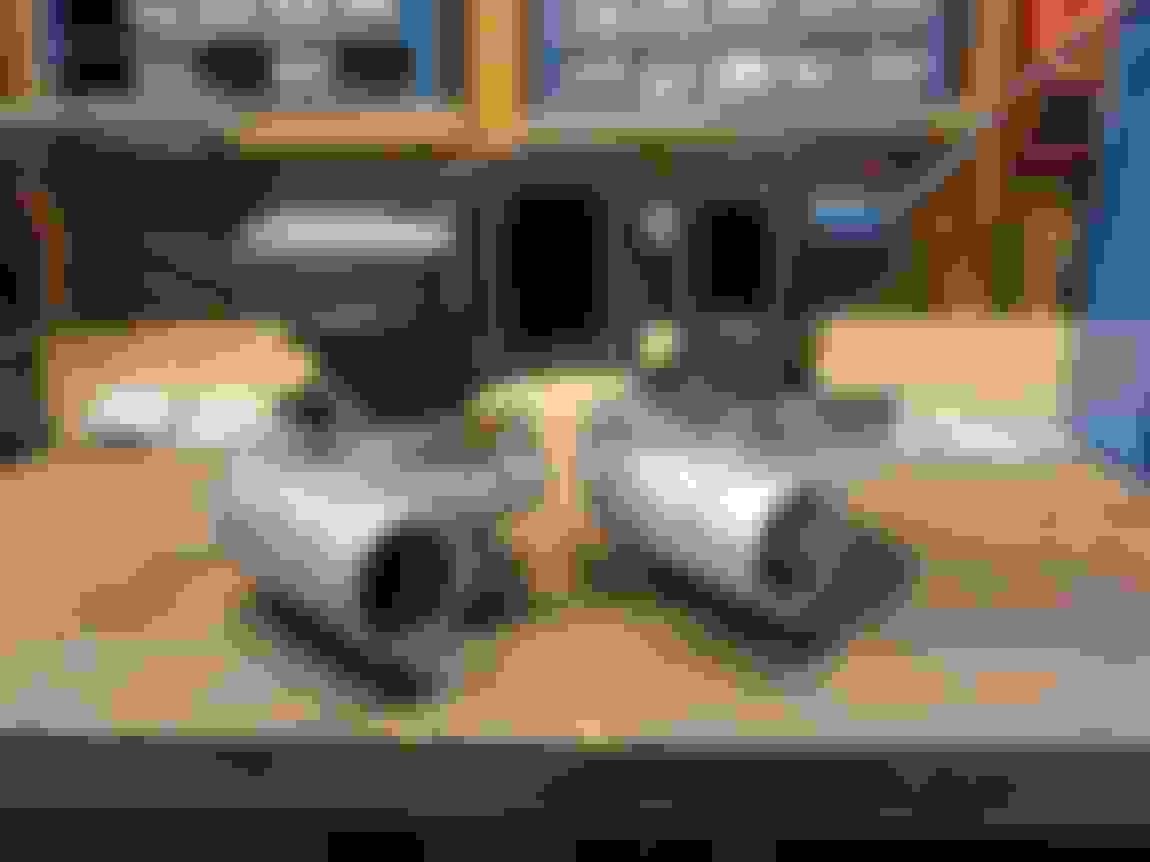
I had a solid afternoon in the garage today. Went from never having mocked up the actual twins to having one side more or less tack welded together in an orientation that looks good for tire (and later inner fender) clearance, taking in mind feasible symmetry between both sides.
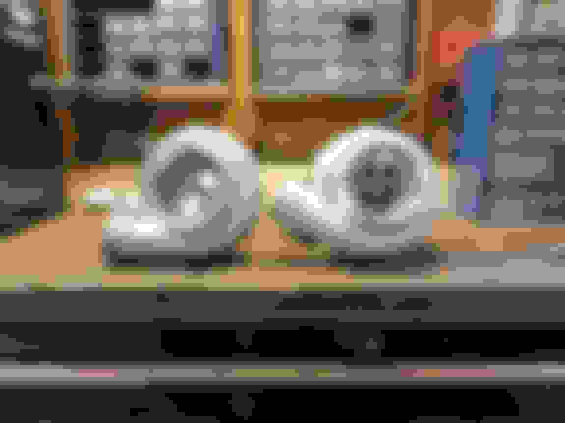
But first, some Precision equipment in a not-so-high-precision shed of a garage! Haha
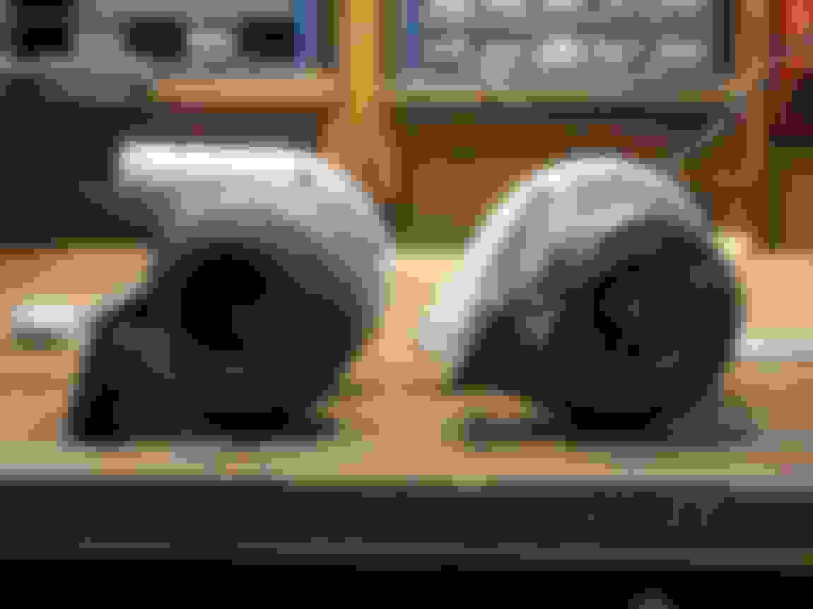
And here are some comparison pictures if this helps anyone else out there. In all my research it was really difficult to get any reliable outside dimensions from any turbo maker, so here is a sizing comparison of the 6466 to a Turbonetics TC-76.. they're practically identical in size. That Turbonetics is one small envelope for a 76mm turbo. No wonder it choked out and wasn't nearly the beast that the old PT7675 was.
I was surprised to find that the T3 inlet flange I sourced from Ace Race Parts was massively off of the T3 Precision housing inlet. Guess I'll have to order matching inlet flanges from Precision, just bummed because of the wasted porting work I preemptively did. The housing has 10mm holes where the flange has 7/16" holes, and the 6 turbine housing clamp bolts are M8 with a 12mm hex head whereas the compressor housing has 3/8" bolts with 1/2" hex head.. very strange.
I spent about 2 hours methodically changing the x & y location of the turbo as well as the height, trying keeping it inline with the engine then a variety of angles to try and get the combo of best angling for the pre-turbo hotside (and downpipe) and tire clearance at full lock.
I settled on turbo locations that I think will work well.. not finalized, but probably 95% good working location to start fabricating hotside piping as well as roughing out the inner fender.
And started tack welding schedule 40 2.5" SS304. I was a bit hesitant to start just randomly grinding and cutting it in case I screwed it up, as it's expensive and I only got the minimum amount I thought I'd need, but I ended up only having to cut a little bit of straight stuff, and then just massaged a couple elbows with a grinder.
And the last bit of work I got done this afternoon.. a rough cut of the wastegate routing. I put it in a place that should be easy to mirror onto the passenger side, and didn't cut a thru-hole in the pre-turbo piping, I just tacked the wastegate piping on for mockup purposes for now. I think the wastegate downpipe should wrap under and merge back into the turbo downpipe nicely.
The pre-wastegate hotpipe is 0.188" wall schedule 40, so it's also on the thick side, but I think I will add a gusset just because the crotch weld in the front will end up being pretty sharp.
There is about 3" of airgap between the pre-turbo hotside and the P/S reservoir cap, which should be far enough considering there will be relatively-cooler air blowing in that area from the rad fans. I may still make a heat shield or heat tape the top of the reservoir cap.
There is also 1.5" air gap between the wastegate downpipe and the mockup of the radiator fan. The rad+fans mockup is generous (3.5" thick radiator) but the fans are also placed pretty high up, I could move the fans down a bit in real life, as well as the option of moving the rad down ~1" as well.
There was no good way to take a pic of this, but there is a minimum 1/4" gap between the wastegate downpipe or bellow and the pre-turbo hotside.. I think with the bend welded to the turbo downpipe, even with head expansion and vibration, there's no way this bend would rub on the pre-turbo hotside.
And of course, I went thru the effort to make the Precision logo horizontal
Gas Monkey Built a 6-Wheel Ferrari Testarossa With a Corvette LT4 Engine
Slideshow: The controversial Ferrari F6 swaps its original flat-12 for a Corvette Z06-derived LT4 V8 and sends power to four rear wheels through a custom-built drivetrain.
7 Most Reliable High-Performance Engines GM Has Ever Built
Slideshow:These GM engines didn't just make huge power, they survived abuse, boost, track days, and six-digit mileage with a reputation for refusing to quit.
6 Common C5 Corvette Failures and What's Involved In Repairing Them
Slideshow: From wobbling harmonic balancers to failed EBCMs, these are the issues that define long-term C5 ownership and what repairs typically involve.
Retro Modern Bandit Pontiac Trans AM Comes With Burt Reynolds' Autograph
Slideshow: A modern Camaro transformed into a retro icon, this limited-run "Bandit" build blends nostalgia with brute force in a way few revivals manage.
Top 10 Greatest Cadillac V Series Performance Models Ever, Ranked
Slideshow: Cadillac didn't just crash the high-performance luxury vehicle party, it showed up loud, supercharged, and occasionally a little unhinged...
Coachbuilt N2A Anteros Is an LS2-Powered C6 Corvette In Italian Clothes
Slideshow: A one-off sports car that looks like a vintage Italian exotic-but hides a C6 Corvette underneath-just sold for the price of a new mid-engine Corvette.