
Taking the plunge: LS3 into '64 Tempest. Need help with shopping list.
 08-02-2009, 12:11 PM
#161

Thanks for your kind words and offer to help on the compressor mounting. I have already purchased a nice set of compressor brackets from KWiK Performance to move it up high on the passenger side: http://www.kwikperf.com/lsx_ac.html
The belt length that KWiK calls out is a little short according to a guy I know on the 'net who's using the same C6 Corvette accessories and compressor brackets. The Gates K061010 belt (6-RIB 13/16" X 101-5/8") is the one that works with the KWiK brackets.
 08-02-2009, 11:38 PM
#162
.....in the garage finishing the front suspension mock-up.
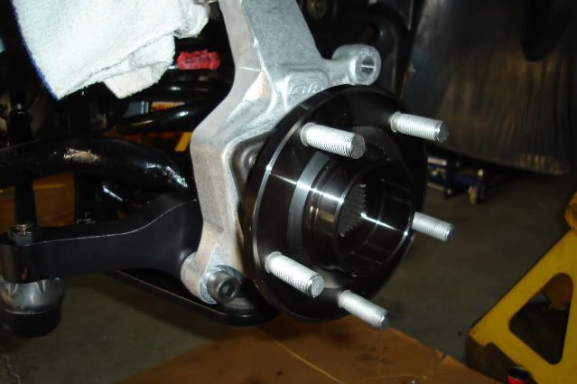
First order of business was to get the SKF racing hubs prepared. For starters, the studs are too long. Since I'm using wheel adapters the studs need to be shortened to match the thickness of the adapters (1.063") plus the thickness of the front brake rotors (.300").
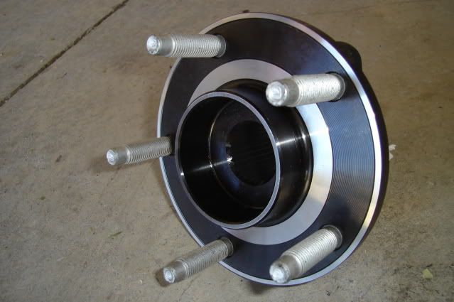
I ended up grinding about .400" off the ends of the studs.
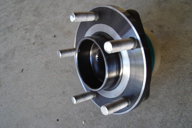
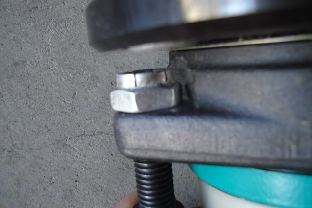
The AFX spindles use two bolts and one stud to mount the hubs. The hubs were designed to use 3 bolts so all three holes are threaded. In order to use the one bottom mounting stud on the AFX spindle I had to drill out the threads in one of the holes with a 1/2" drill bit.
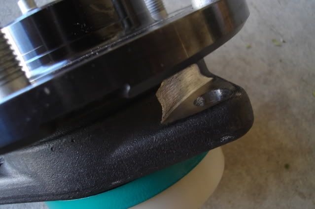
I had to use a die grinder with a cutting wheel to make some clearance for the nut to turn and to provide a flat area for it to tighten down onto.
After having a lot of fun hacking on my new hubs they're now bolted in place.
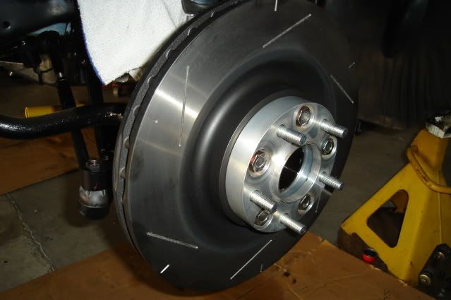
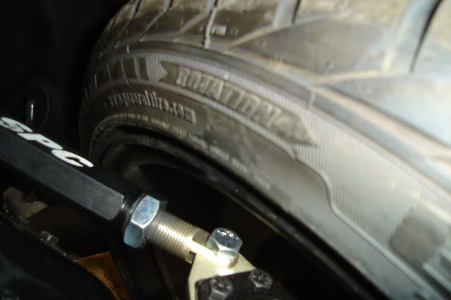
New 14" rotor and wheel adapter mounted up to the hub. The adapter solves two problems, converting the front bolt pattern from 5 on 4.75" (5 on 120.65mm) to 5 on 120mm and effectively reducing the backspacing on the wheel to 5.507" from 6.57". I had to grind about .060" off the ends of the lug nuts holding the adapter in place for clearance.
Bolted the wheel in place. No brake calipers yet, not enough time today with all the drilling and grinding going on.
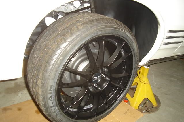
Looks like there's plenty of clearance between the upper A-arm and the inside of the rim with the wheel turned all the way to the left, the clearance here will increase with the car's full weight on the suspension.
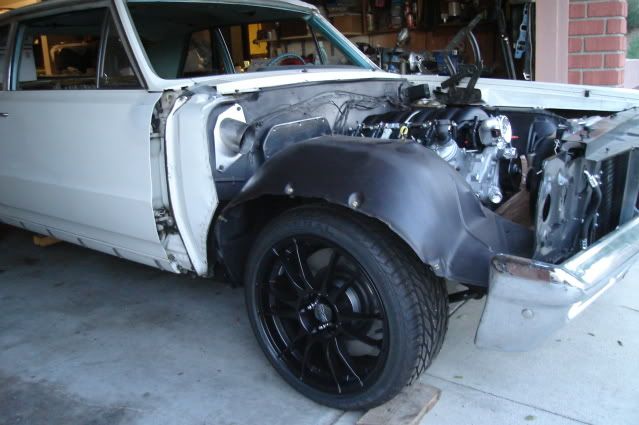
Set the car on the ground to see how it looks. I'm pretty happy with the ride height considering the amount of weight that still needs to be put back in the car. No seats, front or rear glass, most of the exhaust system out, no belt-driven accessories on the engine, no fluids in the engine or trans, no A/C compressor and no hood or right front fender.
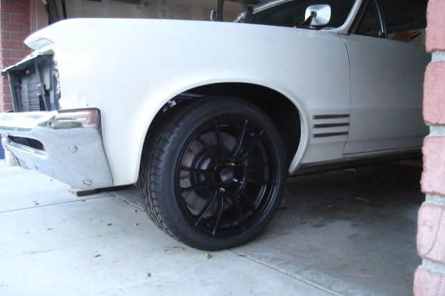
The AFX spindles have 1" of drop built in, combined with the 1" drop from the SPC lower control arms it's looking like I won't need to trim the front springs.
I reached my goal of getting the car sitting back down on the ground on all 4 wheels this weekend.
I'm stoked.
First order of business was to get the SKF racing hubs prepared. For starters, the studs are too long. Since I'm using wheel adapters the studs need to be shortened to match the thickness of the adapters (1.063") plus the thickness of the front brake rotors (.300").
I ended up grinding about .400" off the ends of the studs.
The AFX spindles use two bolts and one stud to mount the hubs. The hubs were designed to use 3 bolts so all three holes are threaded. In order to use the one bottom mounting stud on the AFX spindle I had to drill out the threads in one of the holes with a 1/2" drill bit.
I had to use a die grinder with a cutting wheel to make some clearance for the nut to turn and to provide a flat area for it to tighten down onto.
After having a lot of fun hacking on my new hubs they're now bolted in place.
New 14" rotor and wheel adapter mounted up to the hub. The adapter solves two problems, converting the front bolt pattern from 5 on 4.75" (5 on 120.65mm) to 5 on 120mm and effectively reducing the backspacing on the wheel to 5.507" from 6.57". I had to grind about .060" off the ends of the lug nuts holding the adapter in place for clearance.
Bolted the wheel in place. No brake calipers yet, not enough time today with all the drilling and grinding going on.
Looks like there's plenty of clearance between the upper A-arm and the inside of the rim with the wheel turned all the way to the left, the clearance here will increase with the car's full weight on the suspension.
Set the car on the ground to see how it looks. I'm pretty happy with the ride height considering the amount of weight that still needs to be put back in the car. No seats, front or rear glass, most of the exhaust system out, no belt-driven accessories on the engine, no fluids in the engine or trans, no A/C compressor and no hood or right front fender.
The AFX spindles have 1" of drop built in, combined with the 1" drop from the SPC lower control arms it's looking like I won't need to trim the front springs.
I reached my goal of getting the car sitting back down on the ground on all 4 wheels this weekend.
I'm stoked.
Last edited by b-man64; 08-04-2009 at 11:07 PM. Reason: added more content

 08-05-2009, 08:20 PM
#167
On The Tree
iTrader: (3)
Join Date: Jun 2007
Location: Syracuse, NY
Posts: 184
Likes: 0
Received 0 Likes
on
0 Posts
I can honestly say i just read the whole thread, and that my friend is going to be amazing when its done.
That is exactly what i would do, I love those 64 tempest's, I don't think you could pick a nicer car.
Can't wait to see it done!
Best of luck with it!
--Mike
That is exactly what i would do, I love those 64 tempest's, I don't think you could pick a nicer car.
Can't wait to see it done!
Best of luck with it!
--Mike
08-09-2009, 11:45 PM
#168
.....somewhat unfamiliar territory as it's time for me to start installing the wiring harness and controller.
The engine harness part of it is pretty straight-forward, just match up the connectors and plug them in. Figuring out the best place to mount the bulky ECM is a bit of a challenge, there's pretty much no room under the dash for it with the A/C unit and ducting hoses taking up most of the space on the passenger side.
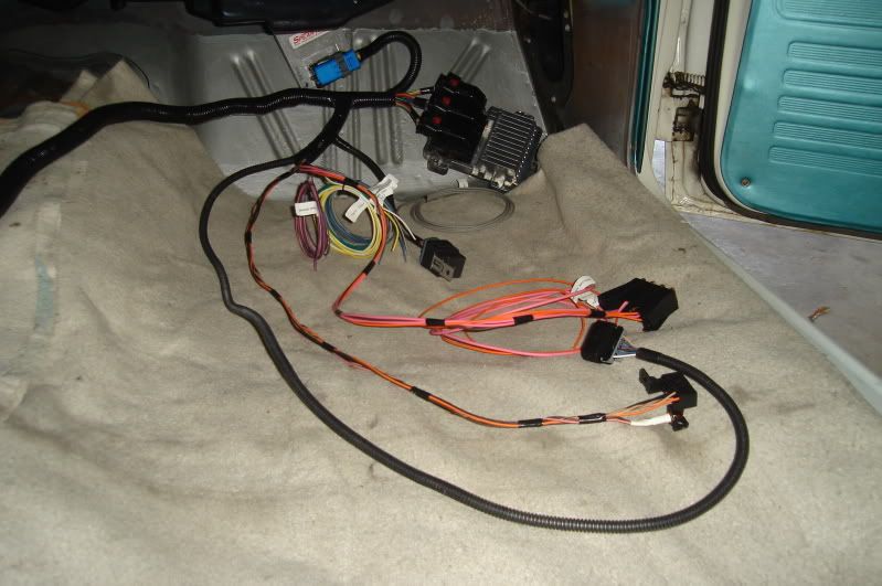
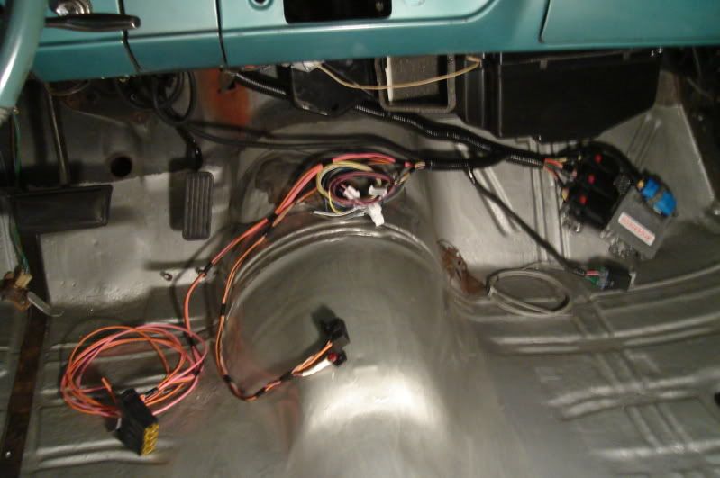
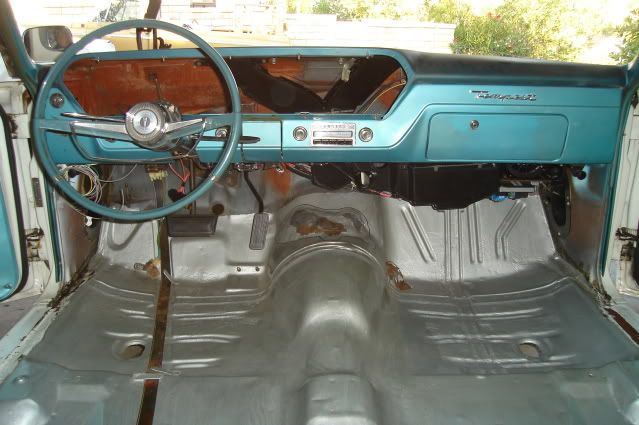
I laid out the harness inside the car to start becoming familiar with it. Everything shown here on the passenger side floor will be on the inside of the firewall. Included is the ECM, pedal harness for the electronic throttle control, fuel pump relay, cruise control wiring, and four 20-amp fuses and power up wires.
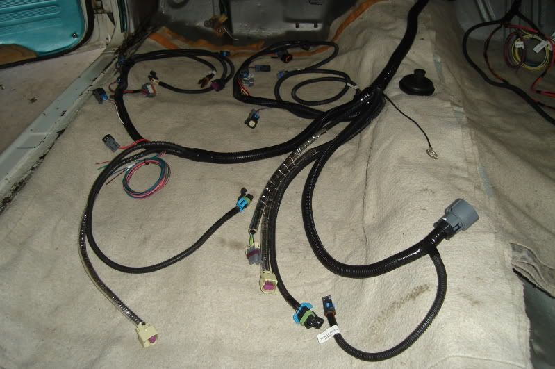
Here on the driver's side the engine harness is laid out. All of the wiring and connectors shown here will have to pass through a 2-1/8" hole in the firewall. Finding a good place to cut that hole is my first task.
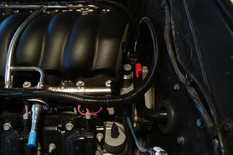
After taking the harness to the engine side of the firewall and plugging it into most of the connectors on the engine and transmission I was able to figure out a good place to run the harness through the firewall. The hole where the throttle cable used to reside looks pretty much ideal.
After marking the outline of the 2-1/8" hole using a piece of 2-1/8" O.D. exhaust tubing (2" pipe expanded for a slip fit over 2" pipe) I drilled a series of small holes just inside the line.
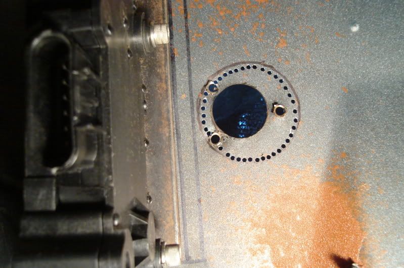
A sharp chisel was used to make quick work of the material that was left between the holes, a half-round file finishes off the edges.
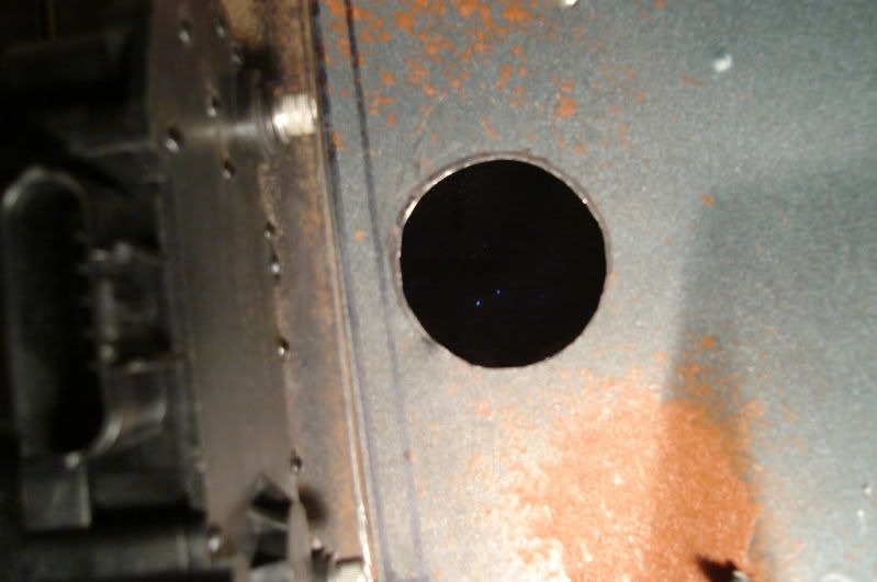
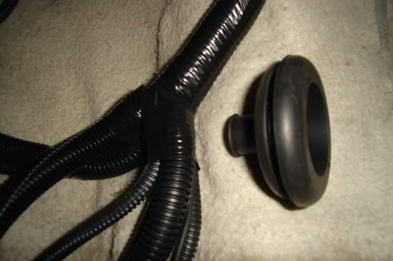
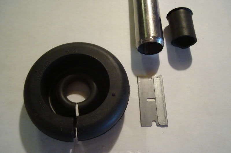
My next dilemma, how to go about getting the harness through this grommet and properly sealing the grommet to both the firewall and harness.
Clearly the harness can't fiit through the grommet without cutting the I.D. of the grommet. The big harness junction shown here would take about a 1" hole stretched out to 1.5" at the very minimum to pass it through the grommet, the grommet only has a 5/8" hole in it.
What to do? Cut the hole a little bigger and try work the entire engine side of the harness through the grommet, or slice it down one side and just slip it over the main cable bundle. Even if I slice it the 5/8" hole still won't be big enough for the 15/16" diameter main cable bundle to pass through.
Any opinions or personal experiences would be much appreciated.
Made a little more progress this weekend, thanks for looking!
The engine harness part of it is pretty straight-forward, just match up the connectors and plug them in. Figuring out the best place to mount the bulky ECM is a bit of a challenge, there's pretty much no room under the dash for it with the A/C unit and ducting hoses taking up most of the space on the passenger side.
I laid out the harness inside the car to start becoming familiar with it. Everything shown here on the passenger side floor will be on the inside of the firewall. Included is the ECM, pedal harness for the electronic throttle control, fuel pump relay, cruise control wiring, and four 20-amp fuses and power up wires.
Here on the driver's side the engine harness is laid out. All of the wiring and connectors shown here will have to pass through a 2-1/8" hole in the firewall. Finding a good place to cut that hole is my first task.
After taking the harness to the engine side of the firewall and plugging it into most of the connectors on the engine and transmission I was able to figure out a good place to run the harness through the firewall. The hole where the throttle cable used to reside looks pretty much ideal.
After marking the outline of the 2-1/8" hole using a piece of 2-1/8" O.D. exhaust tubing (2" pipe expanded for a slip fit over 2" pipe) I drilled a series of small holes just inside the line.
A sharp chisel was used to make quick work of the material that was left between the holes, a half-round file finishes off the edges.
My next dilemma, how to go about getting the harness through this grommet and properly sealing the grommet to both the firewall and harness.
Clearly the harness can't fiit through the grommet without cutting the I.D. of the grommet. The big harness junction shown here would take about a 1" hole stretched out to 1.5" at the very minimum to pass it through the grommet, the grommet only has a 5/8" hole in it.
What to do? Cut the hole a little bigger and try work the entire engine side of the harness through the grommet, or slice it down one side and just slip it over the main cable bundle. Even if I slice it the 5/8" hole still won't be big enough for the 15/16" diameter main cable bundle to pass through.
Any opinions or personal experiences would be much appreciated.
Made a little more progress this weekend, thanks for looking!
08-15-2009, 12:28 AM
#169
.....through the hole in the firewall today. I carefully deburred and sanded the inside of the hole smooth with 180 grit paper and touched it up with some black paint to keep the edges from rusting beforehand.
Here you can see where the main harness branches off into several smaller ones, that part of the harness will reside just behind the passenger side cylinder head.
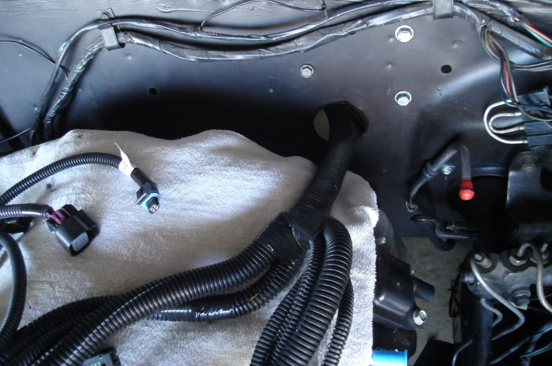
I cut the hole in the grommet to 3/4" using a piece of 3/4" I.D. tubing with the end sharpened, the main harness is about 15/16" in diameter. Using a fresh new razor blade I made a cut in the grommet.
The engine harness fits pretty nicely, there is enough room for it to tuck against the firewall away from the back of the engine. The grommet went in easily and will need some sealer around the harness later when I'm through messing with it, if I don't like the way it's working out I can buy an aftermarket split grommet later on.
The wiring provided (blue, green & pink) for control of the fan relays can be seen at the very bottom of the pic. I have two Bosch 30 amp relays here (0 332 019 150) that perhaps I can use for the fans, I'm not sure if they're the correct ones to use.
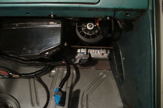
I need to come up with a bracket or plate to mount the ECM (Engine Control Module) in this spot just to the left of the passenger side kick panel. I can't get it mounted up any higher as it will interfere with the A/C unit. It will be up high enough to be out of the way of my passenger's feet, but still easily accessible.
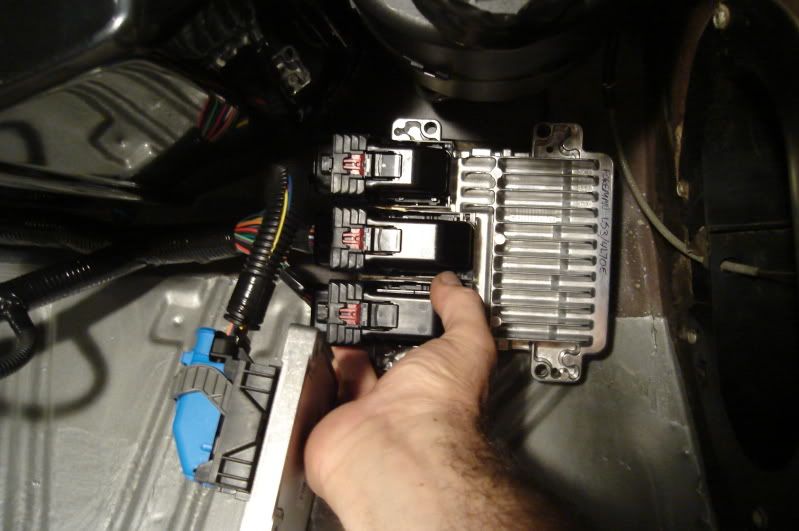
I can mount this TCM (Transmission Control Module) unit over the top of the ECM, leaving about an inch of air space between them for cooling airflow.
With the engine side of the harness out of the way it doesn't look too bad in here. On the driver's side you can see the 4 fuses (#1- Battery, #2- Injection & Ignition, #3- O2 heaters, #4- Fuel pump) which can be mounted right next to the original fuse panel.
On the trans hump is the diagnostic port/check engine light unit. Closer to the firewall on the hump is the wiring rolled up for the cruise control, brake switch (for cruise control disengagement, needs to be a 4 terminal type of brake switch), tach, electric speedo (which I won't be using) and A/C compressor.
On the passenger side is the ECM and TCM units and fuel pump relay. The ETC (electronic throttle control) pedal harness has a little extra length that will need to be looped and tied up. All in all it should be a pretty simple and neat installation when it's done, of course figuring a few things out along the way will be more than just a little challenging.
Tomorow I'll try to fab up the mounting brackets I need for the ECM and find a home for the fuses, fuel pump relay and diagnostic port/check engine light unit.
Here you can see where the main harness branches off into several smaller ones, that part of the harness will reside just behind the passenger side cylinder head.
I cut the hole in the grommet to 3/4" using a piece of 3/4" I.D. tubing with the end sharpened, the main harness is about 15/16" in diameter. Using a fresh new razor blade I made a cut in the grommet.
The engine harness fits pretty nicely, there is enough room for it to tuck against the firewall away from the back of the engine. The grommet went in easily and will need some sealer around the harness later when I'm through messing with it, if I don't like the way it's working out I can buy an aftermarket split grommet later on.
The wiring provided (blue, green & pink) for control of the fan relays can be seen at the very bottom of the pic. I have two Bosch 30 amp relays here (0 332 019 150) that perhaps I can use for the fans, I'm not sure if they're the correct ones to use.
I need to come up with a bracket or plate to mount the ECM (Engine Control Module) in this spot just to the left of the passenger side kick panel. I can't get it mounted up any higher as it will interfere with the A/C unit. It will be up high enough to be out of the way of my passenger's feet, but still easily accessible.
I can mount this TCM (Transmission Control Module) unit over the top of the ECM, leaving about an inch of air space between them for cooling airflow.
With the engine side of the harness out of the way it doesn't look too bad in here. On the driver's side you can see the 4 fuses (#1- Battery, #2- Injection & Ignition, #3- O2 heaters, #4- Fuel pump) which can be mounted right next to the original fuse panel.
On the trans hump is the diagnostic port/check engine light unit. Closer to the firewall on the hump is the wiring rolled up for the cruise control, brake switch (for cruise control disengagement, needs to be a 4 terminal type of brake switch), tach, electric speedo (which I won't be using) and A/C compressor.
On the passenger side is the ECM and TCM units and fuel pump relay. The ETC (electronic throttle control) pedal harness has a little extra length that will need to be looped and tied up. All in all it should be a pretty simple and neat installation when it's done, of course figuring a few things out along the way will be more than just a little challenging.
Tomorow I'll try to fab up the mounting brackets I need for the ECM and find a home for the fuses, fuel pump relay and diagnostic port/check engine light unit.
Last edited by b-man64; 08-19-2009 at 09:57 PM.
08-16-2009, 03:07 AM
#170
.....that I might need in my next lifetime.
Lucky for me I found an old bracket in my stash of junk that was already pretty close to what I need to mount the ECM.
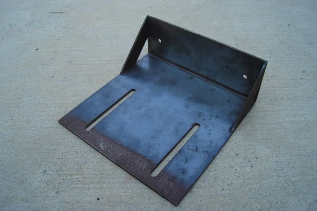
All I need to do now is to remove what doesn't look like an ECM mounting bracket.
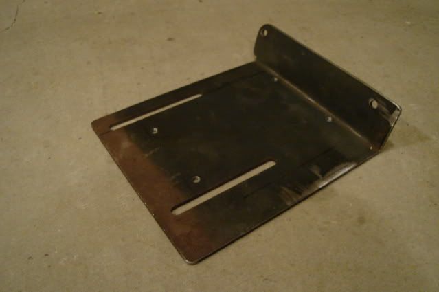
After trimming 1" off the right side and 1" off the bottom (losing the welded side braces in the process) and drilling & tapping the 4 holes 1/4-28 that mount the ECM the bracket is done. The firewall angles back a bit so I had to increase the 90 degree bend angle of the bracket by about 10 degrees to get the ECM to sit level and tuck up as far as possible.
The ECM doesn't sit any lower than the bottom of the A/C unit so it will not be in the way of my passenger's feet. I still need to mount the TCM to the front edge of the bracket.
The kick panel didn't need any mods, it still fits just like the factory intended. I can crack open the vent on this side to provide a bit of fresh air flow for both the ECM and A/C unit.
It's nice to have easy access to these units even if they aren't all that pretty to look at where they're mounted. Making things easier to service whenever possible is constantly on my mind during this build.
Well, that killed most of my day. Just figuring out what to do and finding whatever materials you need to proceed takes a lot of time, in a fully-equipped shop things definitely go a lot faster.
Lucky for me I found an old bracket in my stash of junk that was already pretty close to what I need to mount the ECM.
All I need to do now is to remove what doesn't look like an ECM mounting bracket.
After trimming 1" off the right side and 1" off the bottom (losing the welded side braces in the process) and drilling & tapping the 4 holes 1/4-28 that mount the ECM the bracket is done. The firewall angles back a bit so I had to increase the 90 degree bend angle of the bracket by about 10 degrees to get the ECM to sit level and tuck up as far as possible.
The ECM doesn't sit any lower than the bottom of the A/C unit so it will not be in the way of my passenger's feet. I still need to mount the TCM to the front edge of the bracket.
The kick panel didn't need any mods, it still fits just like the factory intended. I can crack open the vent on this side to provide a bit of fresh air flow for both the ECM and A/C unit.
It's nice to have easy access to these units even if they aren't all that pretty to look at where they're mounted. Making things easier to service whenever possible is constantly on my mind during this build.
Well, that killed most of my day. Just figuring out what to do and finding whatever materials you need to proceed takes a lot of time, in a fully-equipped shop things definitely go a lot faster.
Last edited by b-man64; 08-19-2009 at 10:02 PM.
08-16-2009, 10:51 PM
#171
.....in the garage finishing up mounting the control units today. Once you get some major items in place it makes finding places for the other little things a bit easier.
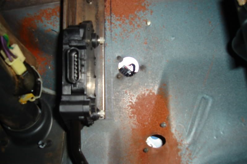
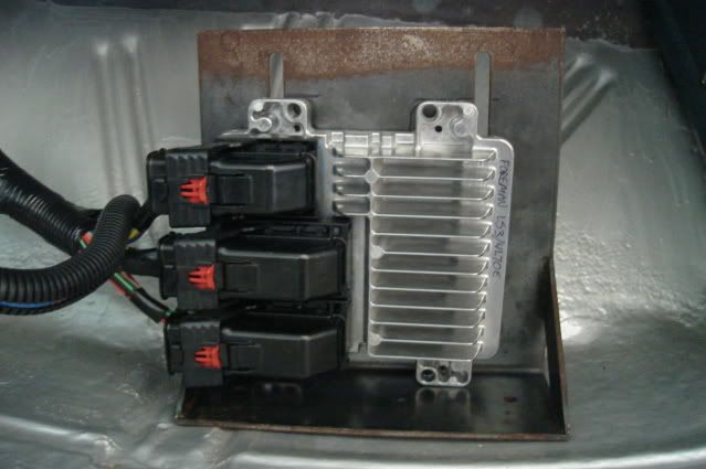
The TCM found a home next to the ECM. The ECM mounts on four .300" tall standoffs made of 3/8" O.D. brake line tubing. Both units can be bolted to the mounting plate first, then the plate mounts on two 1/4-20 X 3/4" studs on the firewall.
The two studs are actually button head screws threaded into the firewall from the engine side after tapping the sheetmetal 1/4-20. They were snugged down enough so that they won't turn but not so tight that they strip that one thread out of the sheetmetal. A little strip caulk body sealer under the bolt head and flat washer keeps them water tight and helps lock them in place.
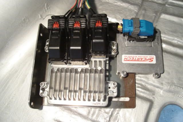
The fuel pump relay found a home on one of the ECM mounting bolts. I'll probably come up with a simple sheetmetal cover painted gloss black to hide the ECM/TCM/fuel pump relay unit later on.
This low-angle shot shows the wiring bundled up and pulled to the driver's side and zip tied to keep it in order. The white zip ties are temporary and will be replaced with black ones. I'll get another piece of black harness sleeving to cover up the colored wires and tidy things up when everything is finalized on the wiring.
You can barely see any of the wiring here, it really isn't visible unless you get down pretty low. I'm glad I didn't try to stuff it all up inside the dash.
Little by little.
Thanks for looking.
The TCM found a home next to the ECM. The ECM mounts on four .300" tall standoffs made of 3/8" O.D. brake line tubing. Both units can be bolted to the mounting plate first, then the plate mounts on two 1/4-20 X 3/4" studs on the firewall.
The two studs are actually button head screws threaded into the firewall from the engine side after tapping the sheetmetal 1/4-20. They were snugged down enough so that they won't turn but not so tight that they strip that one thread out of the sheetmetal. A little strip caulk body sealer under the bolt head and flat washer keeps them water tight and helps lock them in place.
The fuel pump relay found a home on one of the ECM mounting bolts. I'll probably come up with a simple sheetmetal cover painted gloss black to hide the ECM/TCM/fuel pump relay unit later on.
This low-angle shot shows the wiring bundled up and pulled to the driver's side and zip tied to keep it in order. The white zip ties are temporary and will be replaced with black ones. I'll get another piece of black harness sleeving to cover up the colored wires and tidy things up when everything is finalized on the wiring.
You can barely see any of the wiring here, it really isn't visible unless you get down pretty low. I'm glad I didn't try to stuff it all up inside the dash.
Little by little.
Thanks for looking.
Last edited by b-man64; 08-19-2009 at 10:11 PM.
08-16-2009, 10:59 PM
#172
Launching!
iTrader: (13)
Join Date: Feb 2008
Location: Riverside, Ca
Posts: 266
Likes: 0
Received 0 Likes
on
0 Posts
B-man I must say you are doing one hell of a job. I will have to admit seeing your project come together is what has put my *** in gear to work on my car. It sat for several months due to $$$ and I know I can do most of what I was going to pay some else to do.
Thanx keep the pix coming as its great motivation all of us. (Also a Pro-touring member)
Thanx keep the pix coming as its great motivation all of us. (Also a Pro-touring member)
 08-18-2009, 11:54 PM
#174
Thanks guys, I appreciate the kind words. 
Today I was looking for a good place to mount my transmission cooler. The air conditioning condensor takes up the space in front of the radiator where I was first thinking of putting it. There is not enough room up front anywhere behind the bumper.
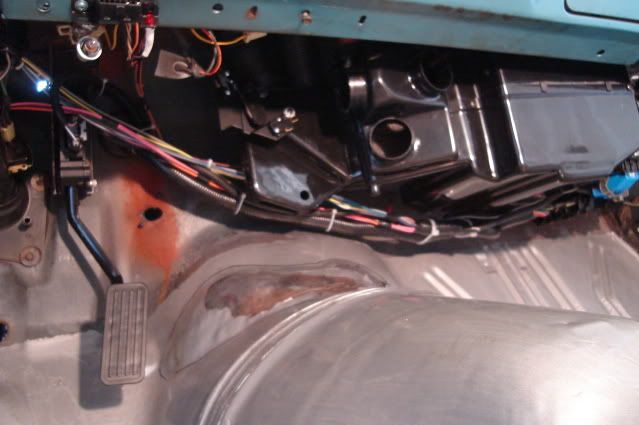
I am considering mounting it to the passenger side frame rail and to the two floor pan braces just above it. It will go directly behind the body mount brace just underneath the passenger seat.
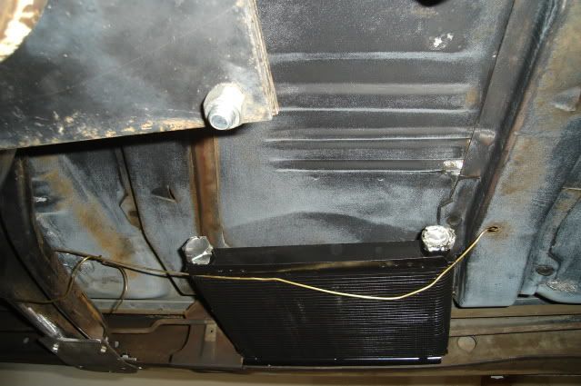
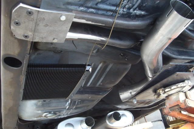
There is plenty of clearance between the exhaust system and the cooler, the X-crossover is directly across from it so the hot exhaust pipes will be as far away from it as would be possible. I can run the 3/8" steel cooler lines going across to the trans just above the trans crossmember to keep the heat transfer from the hot exhaust minimized as much as possible.
Does anyone see a problem with this approach? With the car moving down the road at normal traffic speeds I would think there would be plenty of airflow.
Would stones or road debris kicked up by the right front tire tend to damage it? The B&M Supercooler I'll be using is a plate-type design that is more resistant to impacts than the tube & fin-type coolers. It's not like there are a bunch of stone chips on the bottom of the floorpans already.
I know that cast aluminum framerail mounted coolers are available, but they don't look like they would cool nearly as well as the plate type cooler I have.
Any helpful input would be appreciated.
Today I was looking for a good place to mount my transmission cooler. The air conditioning condensor takes up the space in front of the radiator where I was first thinking of putting it. There is not enough room up front anywhere behind the bumper.
I am considering mounting it to the passenger side frame rail and to the two floor pan braces just above it. It will go directly behind the body mount brace just underneath the passenger seat.
There is plenty of clearance between the exhaust system and the cooler, the X-crossover is directly across from it so the hot exhaust pipes will be as far away from it as would be possible. I can run the 3/8" steel cooler lines going across to the trans just above the trans crossmember to keep the heat transfer from the hot exhaust minimized as much as possible.
Does anyone see a problem with this approach? With the car moving down the road at normal traffic speeds I would think there would be plenty of airflow.
Would stones or road debris kicked up by the right front tire tend to damage it? The B&M Supercooler I'll be using is a plate-type design that is more resistant to impacts than the tube & fin-type coolers. It's not like there are a bunch of stone chips on the bottom of the floorpans already.
I know that cast aluminum framerail mounted coolers are available, but they don't look like they would cool nearly as well as the plate type cooler I have.
Any helpful input would be appreciated.
08-21-2009, 11:26 PM
#175
.....for mounting the trans cooler.
I will mount it up front instead of taking the easy way out and mounting it under the car on the frame where it really won't do a good job and could end up damaged. I had to be reminded that there is a lot of hot air expelled underneath the car from the radiator, engine block and exhaust system.
The one I have is just too a little too big to fit behind the front bumper in front of the radiator and condensor, so I'll just downsize the cooler and get one about half the size so I can put it up front where it really needs to go. The 4L70E overdrive trans with the lockup converter shouldn't put out quite as much heat as one with a non-lockup converter that will by design slip at least a little 100% of the time.
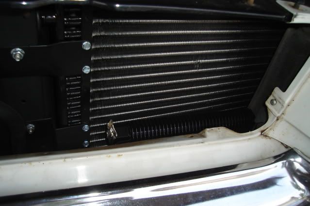
You can see the top of the cooler here, it is 1-1/2" thick and there is only a 2-1/2" space for it. On the left it's just touching the condenser at the bottom corner, it has to follow the angle of the front bumper and grilles in order to fit.
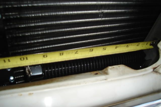
This cooler is 10" wide (as mounted here) including the mounting flanges and has an 8" core width. I will replace it with one of the same design that is 5-3/4" wide with a 3-3/4" core, it will also be 1-1/2" thick like the larger one:http://www.summitracing.com/parts/BMM-70273/
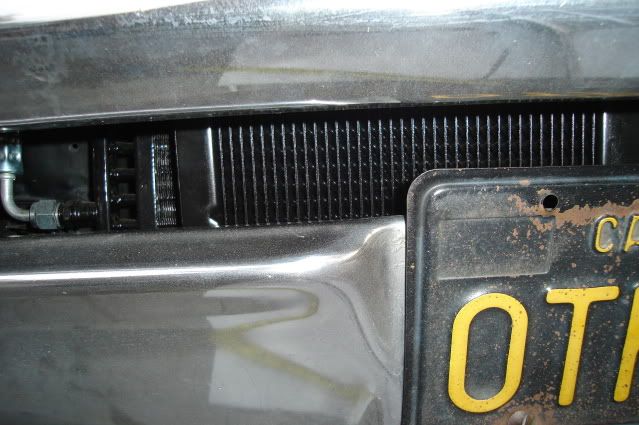
Should get some pretty decent airflow here and not block too much airflow to the condensor and radiator.
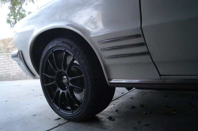
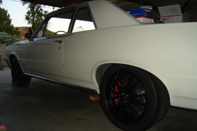
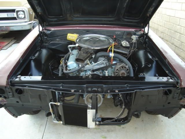
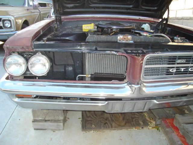
It will mount the same as the trans cooler I have on my GTO shown here, but of course it will only be about half as wide. Plumbing will be done using 3/8" steel hard lines with inverted flare fittings (no rubber hose) like the GTO as well.
Thanks for looking.
I will mount it up front instead of taking the easy way out and mounting it under the car on the frame where it really won't do a good job and could end up damaged. I had to be reminded that there is a lot of hot air expelled underneath the car from the radiator, engine block and exhaust system.
The one I have is just too a little too big to fit behind the front bumper in front of the radiator and condensor, so I'll just downsize the cooler and get one about half the size so I can put it up front where it really needs to go. The 4L70E overdrive trans with the lockup converter shouldn't put out quite as much heat as one with a non-lockup converter that will by design slip at least a little 100% of the time.
You can see the top of the cooler here, it is 1-1/2" thick and there is only a 2-1/2" space for it. On the left it's just touching the condenser at the bottom corner, it has to follow the angle of the front bumper and grilles in order to fit.
This cooler is 10" wide (as mounted here) including the mounting flanges and has an 8" core width. I will replace it with one of the same design that is 5-3/4" wide with a 3-3/4" core, it will also be 1-1/2" thick like the larger one:http://www.summitracing.com/parts/BMM-70273/
Should get some pretty decent airflow here and not block too much airflow to the condensor and radiator.
It will mount the same as the trans cooler I have on my GTO shown here, but of course it will only be about half as wide. Plumbing will be done using 3/8" steel hard lines with inverted flare fittings (no rubber hose) like the GTO as well.
Thanks for looking.
 08-22-2009, 08:17 PM
#177
.....for you guys who know your automotive electrical systems.
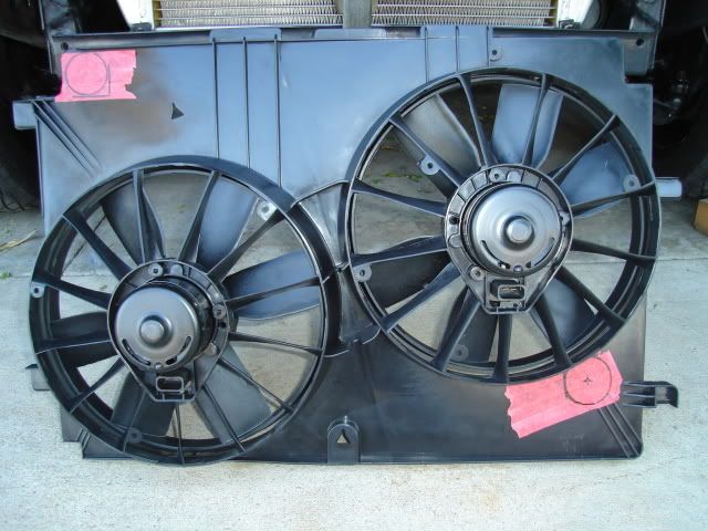
I'm running some 4th-gen F-body fans, they're an OEM replacement made by Dorman (P/N 620634).
Would these require the use of two 30 amp relays or two 40 amp ones? I have two Bosch 30 amp relays (0 332 019 150) here that I might be able to use.
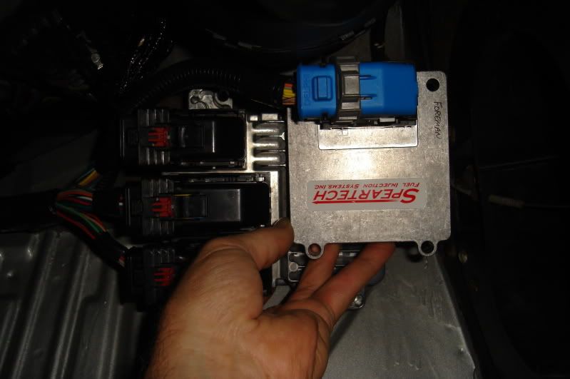
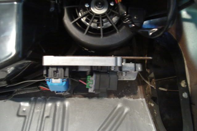
My custom Speartech wiring harness already has provisions for computer control of the fan relays, the loop of pink-dark green-dark blue relay control wires are shown at the bottom of this pic:
Where would you recommend that I source the relay plugs and harnesses from, or some new relays if I need to buy some?
Would also be nice to find the OEM connectors that plug into the fan motors.
Any help you can offer on this would be very much appreciated.
Bart
I'm running some 4th-gen F-body fans, they're an OEM replacement made by Dorman (P/N 620634).
Would these require the use of two 30 amp relays or two 40 amp ones? I have two Bosch 30 amp relays (0 332 019 150) here that I might be able to use.
My custom Speartech wiring harness already has provisions for computer control of the fan relays, the loop of pink-dark green-dark blue relay control wires are shown at the bottom of this pic:
Where would you recommend that I source the relay plugs and harnesses from, or some new relays if I need to buy some?
Would also be nice to find the OEM connectors that plug into the fan motors.
Any help you can offer on this would be very much appreciated.
Bart
08-23-2009, 12:18 PM
#178

You might try Del Mar Wire & Products Corp. for the fan connectors and relay plugs. I know they sell alot of OEM type plugs etc. Unfortunately I don't have their printed catalog and they don't have a website, but their info is:
Del Mar Wire & Products Corp.
1504 E. Francis St.
Ontario, CA 91761
(909) 947-1407
(800) 826-5658
Mon.-Fri. 8am-4pm
As for sizing the relays, are the fans stamped with their rated current draw? Or, do you have any paperwork showing their current draw? If you have a multimeter, specifically an ohmmeter, you can measure the resistance of each fan motor and use Ohm's law to calculate the current draw.... Current (amps) = Voltage (volts)/ Resistance (ohms). Of course you don't want the current draw of the fan motor to exceed the relay rating and personally I would keep the relay rating at least 20% more than the fan motor draw.
Hope this helps.
08-23-2009, 12:32 PM
#179

If you want to go with a plug and play wiring harness you can try out Nelson performance:
http://www.nelsonperformance.com/products.htm#fans
Though it matters whether you're using a parallel or series-parallel wiring scheme.
If you want to build something yourself you could probably source the fan connectors from rockauto and the wiring supplies (relays, relay housings, etc) from waytek wire.
Keep up the awesome work.
09-06-2009, 11:50 PM
#180
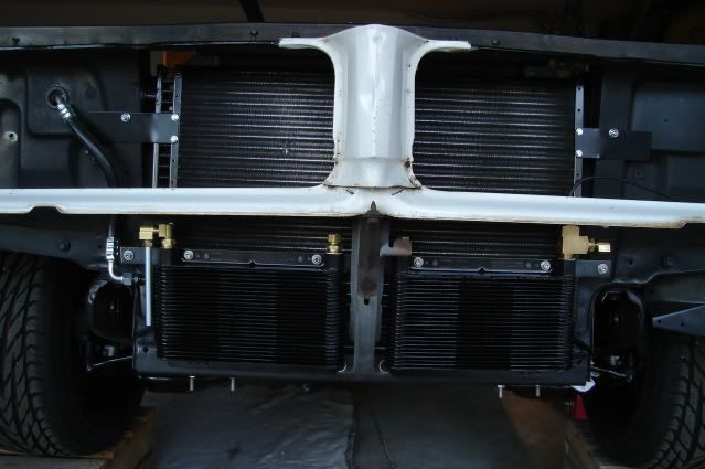
.....for my twin trans coolers.
They tuck right behind the bumper way down low, the top half of the coolers will be exposed to fresh air coming in from the slot in the bumper.
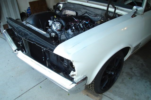
After removing the front bumper this is what I have to work with.
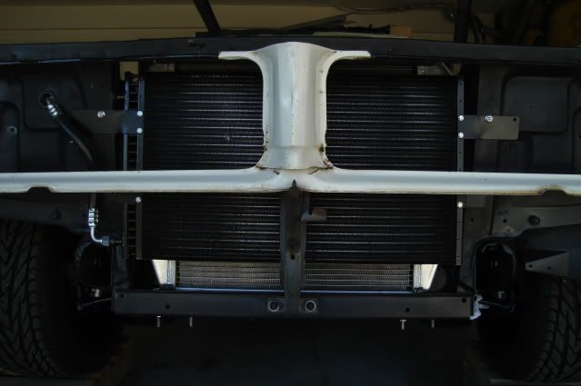
Both coolers are mounted to a piece of 1" wide X 3/16" thick X 29" long mild steel bar. The bar mounts to a pair 1-3/4" long standoffs (spacers), the bar is about 3/8" from the front of the condensor fins. I was able to use two existing 1/4" holes in the core support to mount it, worked out just perfect!
Down below I still need to fab up a pair of lower support brackets from the same mild steel bar, they will bolt to the two lower 3/8" studs that mount the hood latch support in the center and two exisiting 3/8" holes at the bottom corners of the core support channel.
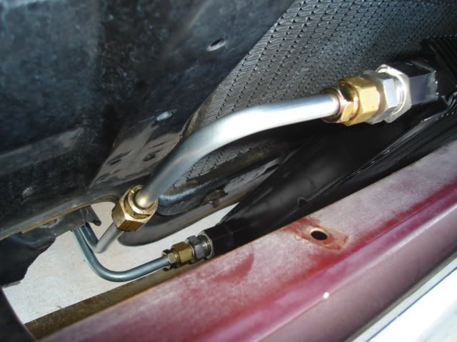
I used a large 1/2 NPT run tee at the top outlet of the second cooler so I could install a trans temp sender for the Autometer trans temp gauge. This should give me a pretty good temperature reading of the cooled fluid before it heads back to the transmission.
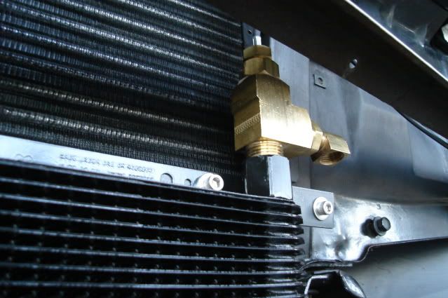
A shot of the 3/8" tube loop that connects the outlet of the first cooler to the inlet of the second cooler. There's plenty of clearance between the tubing loop and the hood latch lever so I won't burn my fingers on the hot tubing. All of the tube fittings are brass inverted flare, already proven to be reliable by the OEMs.
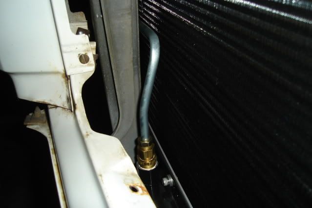
None of the brass fittings or the tube loop can be seen with the bumper and grilles in place, the rest of the cooler plumbing will be hidden behind the bumper as well.
Tomorrow I hope to finish up the plumbing on both coolers and the lower mounting brackets.
Thanks for looking.
They tuck right behind the bumper way down low, the top half of the coolers will be exposed to fresh air coming in from the slot in the bumper.
After removing the front bumper this is what I have to work with.
Both coolers are mounted to a piece of 1" wide X 3/16" thick X 29" long mild steel bar. The bar mounts to a pair 1-3/4" long standoffs (spacers), the bar is about 3/8" from the front of the condensor fins. I was able to use two existing 1/4" holes in the core support to mount it, worked out just perfect!
Down below I still need to fab up a pair of lower support brackets from the same mild steel bar, they will bolt to the two lower 3/8" studs that mount the hood latch support in the center and two exisiting 3/8" holes at the bottom corners of the core support channel.
I used a large 1/2 NPT run tee at the top outlet of the second cooler so I could install a trans temp sender for the Autometer trans temp gauge. This should give me a pretty good temperature reading of the cooled fluid before it heads back to the transmission.
A shot of the 3/8" tube loop that connects the outlet of the first cooler to the inlet of the second cooler. There's plenty of clearance between the tubing loop and the hood latch lever so I won't burn my fingers on the hot tubing. All of the tube fittings are brass inverted flare, already proven to be reliable by the OEMs.
None of the brass fittings or the tube loop can be seen with the bumper and grilles in place, the rest of the cooler plumbing will be hidden behind the bumper as well.
Tomorrow I hope to finish up the plumbing on both coolers and the lower mounting brackets.
Thanks for looking.