
My Stock Internal M6 buid thread...10's???
 09-01-2010, 12:59 PM
#81


No really, I'm not sure... i have lightweight carpet, and a fiberglass hood which is two areas people often overlook... besides that its just normal stuff.. rear seats and belts, no spare, bumper braces and misc little stuff.. theres a ton more weight to be removed if im willing

 09-01-2010, 05:10 PM
#83
They all started out equal
 unless you count that mine has an aluminum frame and all carbon fiber panels
 09-02-2010, 06:24 PM
#88
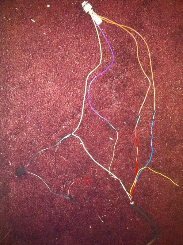
I got my wideband today! I'm trying to figure out how to wire it to my rear 02... I'm a wiring newb and am a little lost 
Any help??
I'm using this as my guide...
Any help??
I'm using this as my guide...
OK, I just got done wiring my LC-1 to be used connected to the rear o2 sensor. I used the following wiring diagram.

The beauty of this set up is that it is self contained. So I can move it between my 2 Fbodies. All I need to do is put the WB into a welded bung. And connect the harness to the rear o2 sensor connector. Then Log with HP tuners. Note the wiring above is looking at the female end of the connector when you wire the male connector into your LC-1 unit you need to take that into account otherwise you will be flipping A and C, and B and D.
As far as the PID I had to do a bit of extra work. First you need to log the rear o2 sensor voltage. It is under Fuel System>Oxigen Sensors>O2 Voltage B1S2 (SAE) (mV) (if connected to the drivers rear O2)/O2 Voltage B2S2 (SAE) (mV) (if connected to the passenger rear O2). Then you need to create a custom PID. I called mine Rear O2 Voltage (WB), under Abbrv: o2 wb, then leave sensor blank and select afr under units. Now in the Function: this is what I used (([PID.21]/1000)/.125)+10. Note the PID.21 is the rear Driver's side o2 you will want PID.25 for the passenger. Also note that I divided the output of the PID by 1,000. The reason for that is that the pid's output is in mV (millivolts) I need the number in volts so I can compare it with my set range output in the LC-1 (0-1v). .125 is derived for 1v/8. As mentioned in previous posts. So now to the AFR Error. I create another custom PID called AFR Error, under Abbrv: AFR E2, then leave sensor blank and select % under units. Now in the Function: this is what I used 100*(((([PID.21]/1000)/.125)+10)-[SENS.121])/[SENS.121]. As far as explanation for this one notice I use the same formula that I used in my wideband pid then I subtracted [SENS.121] (which is the commanded AFR) then divided it by the commanded AFR and multiplied it by 100 to get the percentage of error.
I did a couple of logs tonight and started tunning my VE tables and this is so much easier that using fueltrims. I got my VE pretty close in 2 runs. I need to do another run to verify. But it looking good so far. I'll post a picture later of the harness I made for reference purposes.
Enjoy!
Last edited by Magnet; 12-20-2010 at 06:42 PM.
 09-02-2010, 07:30 PM
#91
the biggest problem im having is that the LC-1 instruction say to have the blue ad white wire on the same ground source, but these direction above have them on different grounds... and i cant tell how to wire the black wire (calibration wire) into the system..
 09-02-2010, 11:02 PM
#93
I really hope you are not trying to wire your controller into your narrow band o2 sensor. The wideband o2 sensor that came with my NGK AFx had it's own connection and wiring harness. It's a direct plug in for a bosch lsu / ngk ntk wideband sensor.
09-03-2010, 01:09 AM
#94
TECH Fanatic
I took out my rear 02's and my driver's side header(kooks) had and extra bung in it for a oxygen sensor, I put it there. Real easy to wire up. I followed the instructions in my hp tuners software. We will figure out soon if i messed up my controller or screwed up my sensor soon cause it quit working in march or may or some chit. Worked fine before until i forgot to tighten it up one day.
09-03-2010, 06:06 AM
#95
Lol no... I don't have the pro version with an Eio so I am going through my rear 02 for my power and ground etc that way it's a plug and play and go from one car to another. If you look I'm wiring into the male side of the 02. I still have to get a bung put in my Exhaust for the wideband sensor...
 09-04-2010, 08:21 PM
#97
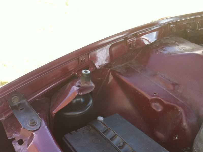
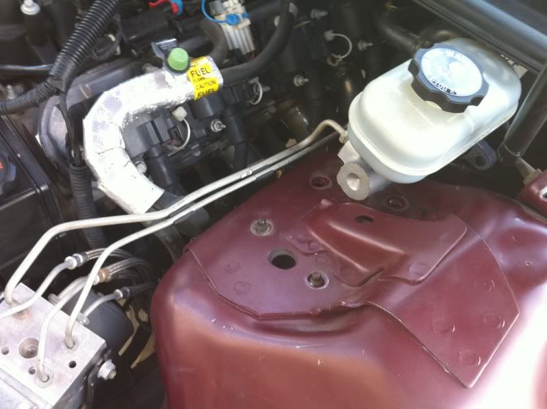
Well i removed the old catch can, and mounted my new one today, pics tomorrow its too dark to take them now. The old can was 4.3lbs and my new can is .6lbs for a net loss of 3.7lbs right off the nose for $20
Anyone know what this is in the pic? Can it go??
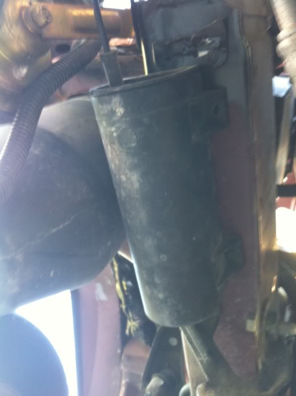
Anyone know what this is in the pic? Can it go??
 09-19-2010, 05:46 PM
#100
Update: Got the QA1's and Comp 3-ways installed this weekend.. wwas a lot easier than I thought it was going to be... They dropped the car a ton.. I wish I would have measured, but I would say it dropped the whole car at least 1.5-2in...
New stance (How do you like the skinnies and 18in z06's together? haha... My front's are getting new tires so I'm running the skinnies for the moment)
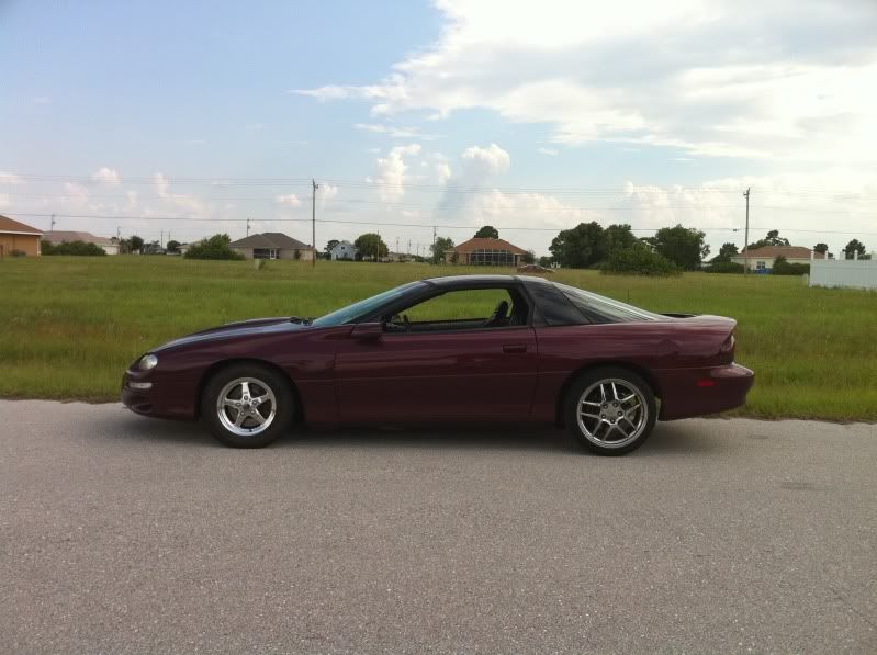
Random pics
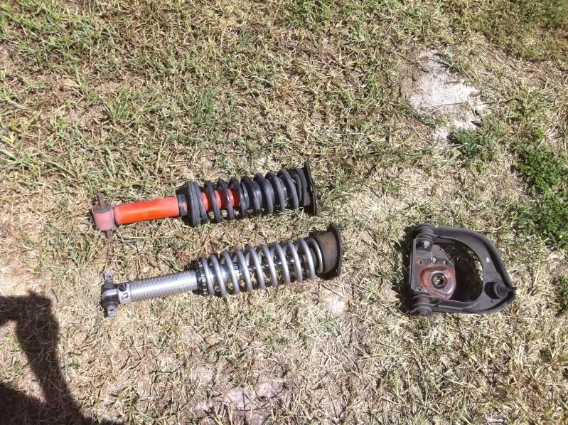
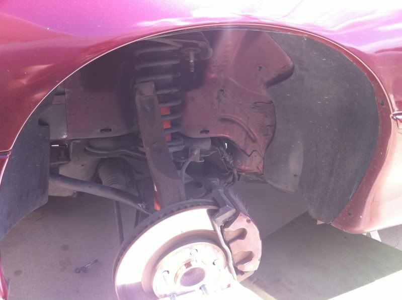
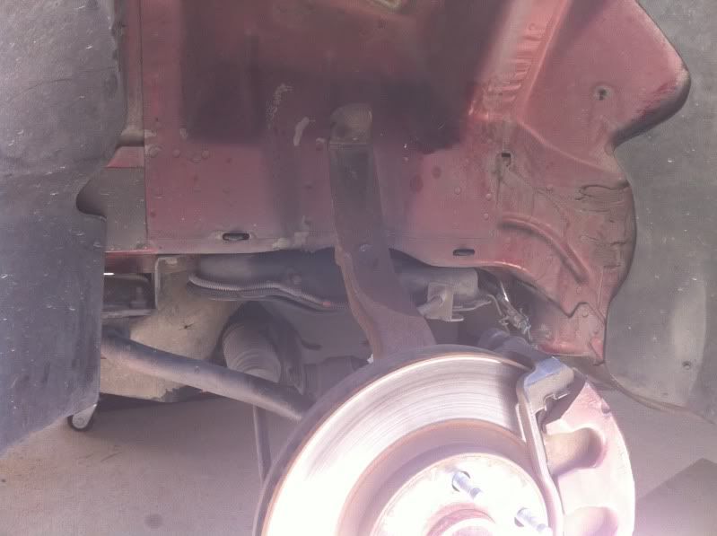
Sorry I always forget to take good pics while I'm working on stuff
Notice the stock a-arms, k-member, front sway bar etc... hopefully changing sooner than later..
New stance (How do you like the skinnies and 18in z06's together? haha... My front's are getting new tires so I'm running the skinnies for the moment)
Random pics
Sorry I always forget to take good pics while I'm working on stuff
Notice the stock a-arms, k-member, front sway bar etc... hopefully changing sooner than later..