2005 GTO/416/CNC 243's/Fast 102/DuSpeed OTR/1x3/4"
#21
....and abviously basic math is above my pay grade too because it was +9 RWTQ with the matchport/102TB/DuSpeed you installed(i fixed the error)
....all told you guys got me +32RWHP and +24RWTQ from tuning and changing my induction set up
....all told you guys got me +32RWHP and +24RWTQ from tuning and changing my induction set up
Last edited by weldermike27408; 11-25-2012 at 07:37 PM.
#22
Thread Starter
FormerVendor
iTrader: (3)
Joined: Feb 2012
Posts: 7,480
Likes: 15
From: Mount Airy, NC
as far as what you were saying about LS3 style head Im not opposed to it cause i could sell 243's with the matchported intake as well..Id like to get a few times in my fat *** GTO first...
my cam may not be optimal for the LS3 heads though but thats way above my paygrade
my cam may not be optimal for the LS3 heads though but thats way above my paygrade
293/305@.006
243/255@.050
166/176@.200
113LSA 108ICL 118ECL
243/255 .624"/.624" 113+5
That is what I would like to see used if you were to use a LS3 head, if you went with a LS7 head I'd like to see even more exhaust duration and possibly putting it on a 114 LSA with a 108 ICL and 120ECL.
That said what you have right now is working beautifully, and you've already got the cam and intake to do it with, so we'll probably stick with it unless you decide to switch it up on us.
Greg does good work and stays under the radar because he's not into the internet "I'm God's gift to racing" sh*t...If he can make a set of 243's work like this it would be intersting to see what you guys could come up with on an aftermarket pro-porter/as-cast head...

#24
Thread Starter
FormerVendor
iTrader: (3)
Joined: Feb 2012
Posts: 7,480
Likes: 15
From: Mount Airy, NC
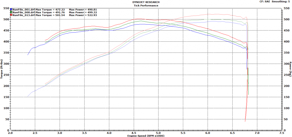
Mike, since you mentioned it yesterday I've overlaid your first dyno pull when your car arrived at our shop before we did any tuning to allow it pass inspection and before we installed the Duspeed OTR intake, before you port matched your intake and before we installed the 102 TB. Then I overlaid that with your dyno graph after we tuned it to allow it to pass inspection. The final highest graph is after the Duspeed intake installation, 102 tb and your port matching.

As you all can see every gain was made across the entire curve, and that is something that you will seriously feel in the seat of your pants every time you drive the car. Mike is always commenting on how we brought the car back to life, after seeing this dyno graph it's clear why he feels that way!

As you all can see every gain was made across the entire curve, and that is something that you will seriously feel in the seat of your pants every time you drive the car. Mike is always commenting on how we brought the car back to life, after seeing this dyno graph it's clear why he feels that way!

#26
Thread Starter
FormerVendor
iTrader: (3)
Joined: Feb 2012
Posts: 7,480
Likes: 15
From: Mount Airy, NC
This is a very simple set-up that I think anyone can duplicate with some initial prior planning and have a very stout combination. With a set of aftermarket heads I only hope we can gain more and make this an even more powerful of a combination.
#27
amazing what a good stroker motor with a good camshaft, heads and port match intake can do!
sometimes its the little stuff that a lot of people miss. port matches being a huge one...
sometimes its the little stuff that a lot of people miss. port matches being a huge one...
#28
Thread Starter
FormerVendor
iTrader: (3)
Joined: Feb 2012
Posts: 7,480
Likes: 15
From: Mount Airy, NC
I too think a lot of the gains were from the port match and the OTR intake itself. Initially me and Mike had planned on doing each mod individually to see where the power was gained as in those types of situations is where you learn more about what really makes the power on these cars.
#32
I'm curious to see what kind of gains the TFS heads make over the ported 243's. From the numbers you made and by looking at the dyno graph, those ported 243's seem to be doing one hell of a job. Are the 243's just CNC ported, or did Greg do some hand blending too? Any idea what the intake port size is?
#33
Thread Starter
FormerVendor
iTrader: (3)
Joined: Feb 2012
Posts: 7,480
Likes: 15
From: Mount Airy, NC
Jim,
That would be a question Mike would have to answer.
Hoping for a large gain! Although Mike has one of if not the strongest running stock cathedral port casting combos I've worked with, a set of aftermarket castings will surely gain horsepower and torque over the 243s. Steeper valve angle, more efficient chamber, better plug location, nitrous exhaust port and a larger runner are all working together in this case. I believe the current intake runner volume is 232cc's and we've decided on a 245cc runner for the new set of heads. Peak horsepower and torque will move up a 100-200 rpm helping to hang that awesome torque curve out further for higher peak horsepower.
That would be a question Mike would have to answer.
I'm curious to see what kind of gains the TFS heads make over the ported 243's. From the numbers you made and by looking at the dyno graph, those ported 243's seem to be doing one hell of a job. Are the 243's just CNC ported, or did Greg do some hand blending too? Any idea what the intake port size is?
#34
Martin, you referrenced a "Nitrous Exhaust Port" when talking about the TFS heads, can you explain to me what that means and if the TFS 220cc As Cast Heads have this as well?
#35
Thread Starter
FormerVendor
iTrader: (3)
Joined: Feb 2012
Posts: 7,480
Likes: 15
From: Mount Airy, NC
This is going to get kind of technical so follow along where you can....at the lowest amounts of valve lift, between .000"-.100" of an inch, the intake and exhaust valve are overlapping one another at TDC. TDC is where the meat of the overlap phase happens. This is where the intake runner is scavenged via the exhaust port. Rush of exhaust gas leaving the cylinder out the exhaust valve/port as it is closing scavenges the intake runner as the intake valve is opening.
Some valve-train/cylinder head/cam guru's like to use aggressive lobes on the exhaust side that have lower seat to seat(.006"-.006") overlap figures. When you have an aggressive lobe it opens and closes faster therefore it is faster off and back on the seat reducing the amount of time the valves actually overlap during overlap. A less aggressive lobe will be slower from seat to seat(.006"-.006") than a more aggressive lobe, which makes the time spent during overlap longer because the valve is opening and closing slower.
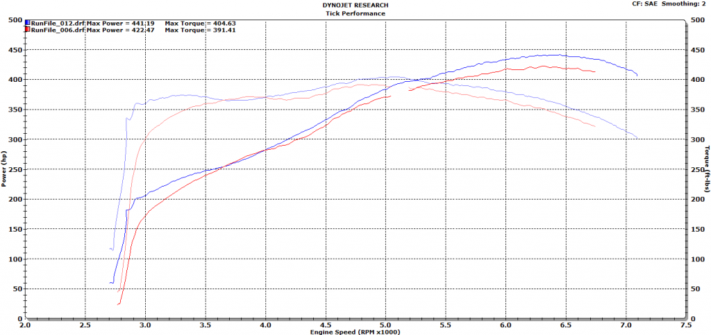
With a long runner intake like a Fast intake or a stock style intake, over-scavenging can cause a dip in the torque curve at low RPM as you can see from the graph of the V.2 Polluter cam I've added below. I overlaid the 112lsa V.2 and the 111lsa V.2 so you can see the differences between 17.5* of overlap and 19.5* of overlap. As you can see one has a bigger dip than the other. This is from overscavenging. Overlap makes great power in the mid-range and up top, but on a long runner intake it sacrifices some low end when that dip arises.

Now, with that in mind, a cylinder head that flows a high amount of CFM on the exhaust at .000"-.100" lift will scavenge the intake runner more than a cylinder head that does not. You're probably thinking, "awesome, more flow is better great! This is what I want"! Well, to gain airflow down low you lose some up top in the meat of the lift curve just to be able to scavenge the intake runner more.
If you have a cylinder head that does flow a lot of CFM on the exhaust side at low lift then you would want to use a more aggressive exhaust lobe so that you do not over scavenge the intake runner. The problem with an aggressive exhaust lobe is valve train noise and stability. The exhaust valve has to open against immense cylinder pressure that is occupying the cylinder after the combustion event has taken place and therefore has to pretty much force it's way open against that pressure. A really aggressive lobe will bounce off the seat if not controlled properly while a milder lobe will not.
My understanding is Tooley, decided that if he could reduce the amount of flow between .000"-.100" in the exhaust port itself, use a less aggressive exhaust lobe with more seat to seat overlap to gain that scavenging lost from the cfm flow at .000"-100" back, and then gain flow from .100"-.600" after reducing flow at .000"-.100" he'd be in turn using everything as a system to his advantage. This would also prevent the over-scavenging issues seen in my dyno graph above and prevent valve-train stability issues from using a more aggressive lobe.
It's been argued back and forth for a while which method is better and for an all out race motor with a solid roller and a single plane intake manifold that needs that intake scavenging due to such a short runner I agree that the nitrous exhaust port and 50* accompanying valve job may not be the best option. That said, for a hydraulic roller with a long runner intake like the majority of LS street cars have, I think it works very well when used in the correct application.
Basically it's a give and take and using everything as as system.
#36
Im extremely close to pulling the trigger TEA TFS 235's .... hoping for some Test'nTune runs Thursday .... gonna spin 'cause I dont have great tires but F**k it !!
Guy who did the 243's is Greg Burkhart GT Racing Heads in North Carolina. He made these heads off of as-cast bare 243's I brought him.He scanned them and went to work doing stuff that would take me forever to even comprehend.Bowls were done by hand Im almost positive.
Guy who did the 243's is Greg Burkhart GT Racing Heads in North Carolina. He made these heads off of as-cast bare 243's I brought him.He scanned them and went to work doing stuff that would take me forever to even comprehend.Bowls were done by hand Im almost positive.
Last edited by weldermike27408; 03-13-2013 at 08:15 PM.
#40


 This thread makes me want to keep my 243s in case I ever get the $$$ for my own LS3 416