
Valve Cover AN Fitting Question for Catchcan
 12-20-2009, 01:39 PM
#1
Staging Lane
Thread Starter

Join Date: Jul 2008
Posts: 70
Likes: 0
Received 0 Likes
on
0 Posts
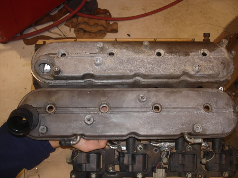

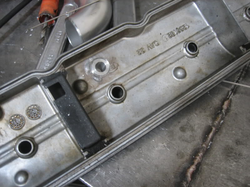
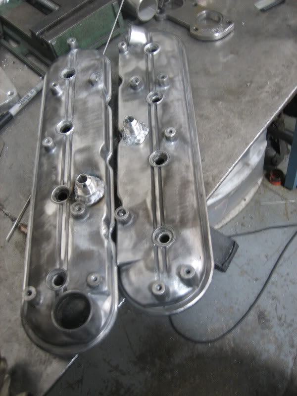
This is for a FI build. I am going to use stock valve covers and stock car coil packs. I am going to get one fitting welded on each valve cover. The top valve cover is for the driver side, I plan on having the fitting welded right in that opening. The bottom valve cover is the passenger side with the oil fill. Would you suggest using the stock passenger side cover with the fill and placing the AN fitting there or would you use another similar valve cover similar to the driver side. The reason I ask is because there is a baffle on the driver side cover and wouldnt be if I used the oil fill location.
Would this suck up a ton of oil?
See second picture for comparison.
Thanks!


 12-20-2009, 02:57 PM
#3
Staging Lane
Thread Starter
Join Date: Jul 2008
Posts: 70
Likes: 0
Received 0 Likes
on
0 Posts
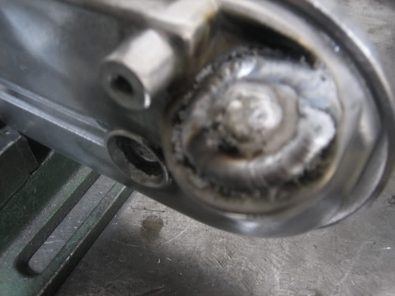
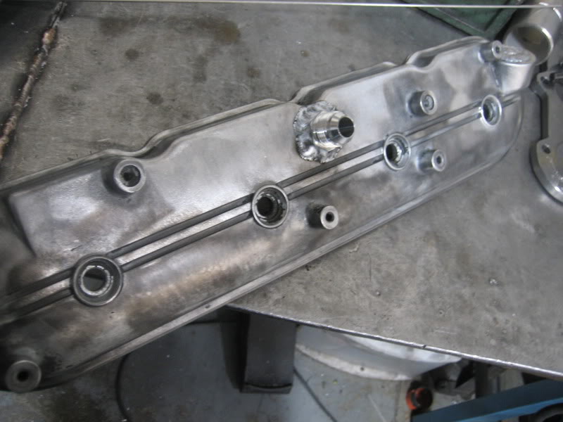
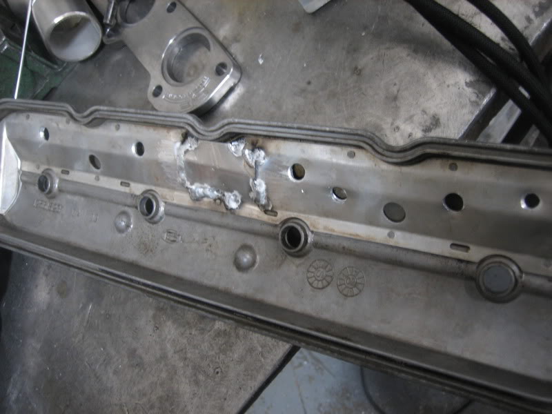
It looks like you decided to make a baffle, so you dont suck up too much oil. Looks good. Where did you relocate your coil packs and why did you relocate them. Are those -10 or -12 fittings?
Thanks.
Thanks.
 12-21-2009, 02:29 AM
#6


Trending Topics
12-21-2009, 07:33 AM
#8
Staging Lane
Thread Starter
Join Date: Jul 2008
Posts: 70
Likes: 0
Received 0 Likes
on
0 Posts
I assume he fills through the an fitting at the passenger side front, just take a little bit longer.
12-21-2009, 09:30 AM
#9
TECH Senior Member
iTrader: (10)
Join Date: May 2005
Location: Bossier city,LA barksdale AFB
Posts: 5,353
Likes: 0
Received 2 Likes
on
2 Posts

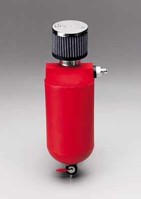
yes he fills buy in bolting it on passenger side and using a funnel. He has a big catch can with breather on top of it down where your air pump would be hidden. I believe it is -10. I think he was thinking about selling these covers at one time. His user name on here is TJ
 12-21-2009, 07:07 PM
#12
TECH Senior Member
iTrader: (10)
Join Date: May 2005
Location: Bossier city,LA barksdale AFB
Posts: 5,353
Likes: 0
Received 2 Likes
on
2 Posts
it simple run lines from valve covers to where ever you mount ya catch can with breather on top.
something i drew up real quick

something i drew up real quick
Last edited by SIC LSX; 12-21-2009 at 07:24 PM.
12-21-2009, 10:48 PM
#15
Staging Lane
Thread Starter
Join Date: Jul 2008
Posts: 70
Likes: 0
Received 0 Likes
on
0 Posts
I am getting fittings welded in like Sic's pictures. I am capping off the valley cover and the TB port. The lines run to the catch can only. The catch can will have a filter.
 12-24-2009, 02:04 AM
#17

In your drawing you show the lines joining together in a T then running in a single hose to the breather tank. If you have the space it is better to run a separate line from each cover to its own fitting on the breather tank. When you do it like you have laid out you are effectively cutting the inner diameter of the final hose by 50% as you ask the single hose to handle both side's flow. Each side should have its own hose, preferably a -10 or larger.
Jim
Jim
12-24-2009, 12:32 PM
#19
On The Tree
iTrader: (13)
Join Date: Sep 2009
Location: League City, TX
Posts: 128
Likes: 0
Received 0 Likes
on
0 Posts
In your drawing you show the lines joining together in a T then running in a single hose to the breather tank. If you have the space it is better to run a separate line from each cover to its own fitting on the breather tank. When you do it like you have laid out you are effectively cutting the inner diameter of the final hose by 50% as you ask the single hose to handle both side's flow. Each side should have its own hose, preferably a -10 or larger.
Jim
Jim
Now with my alcohol Outlaw 10.5 car that made 2200hp, yes I needed to -10 lines to a puke tank, but that was for 30 psi of boost and a Waterman big bertha fuel pump pushing a boat-load of alcohol through the motor. On a street car, even a boosted one, one -10 should be more than sufficient.
