


2001 RCSB GT-42 Build
Thread Starter
TECH Senior Member
iTrader: (8)
Joined: Jan 2007
Posts: 13,845
Likes: 0
From: Here and sometimes there too.
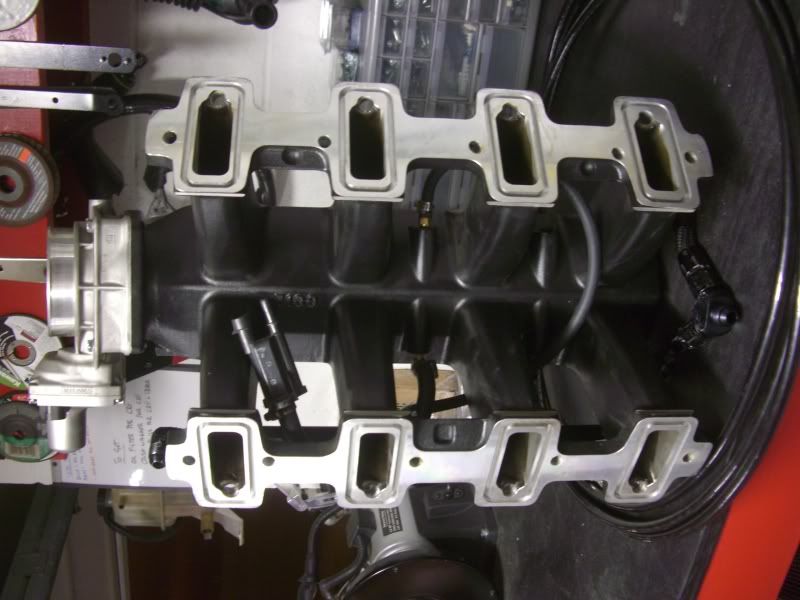
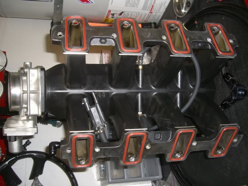
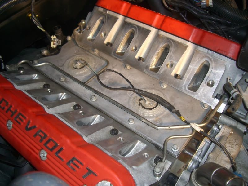
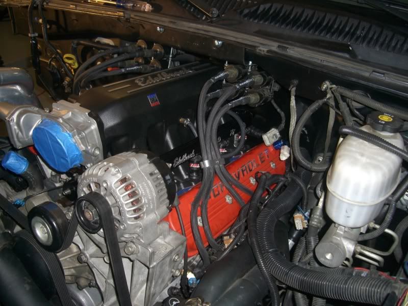
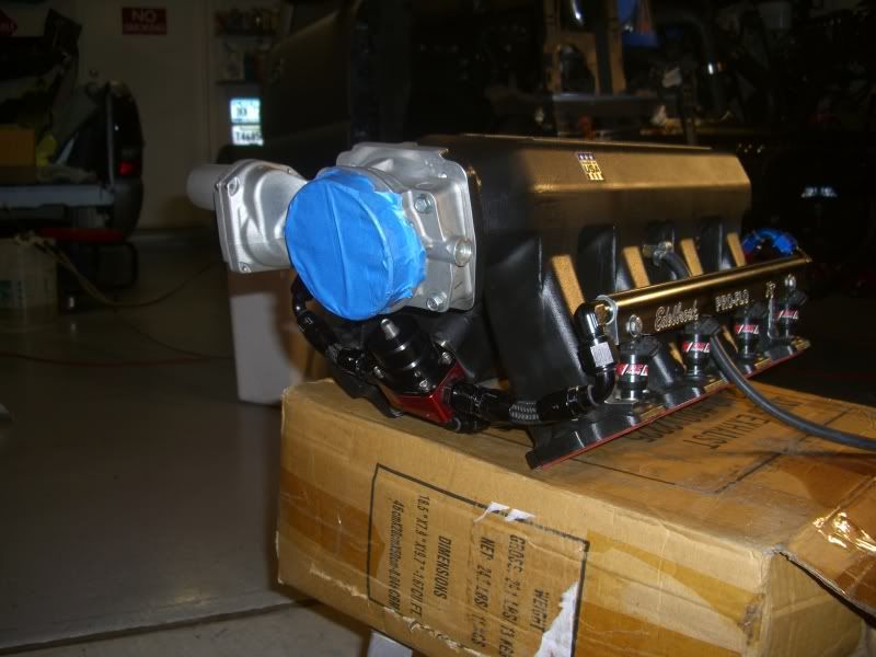
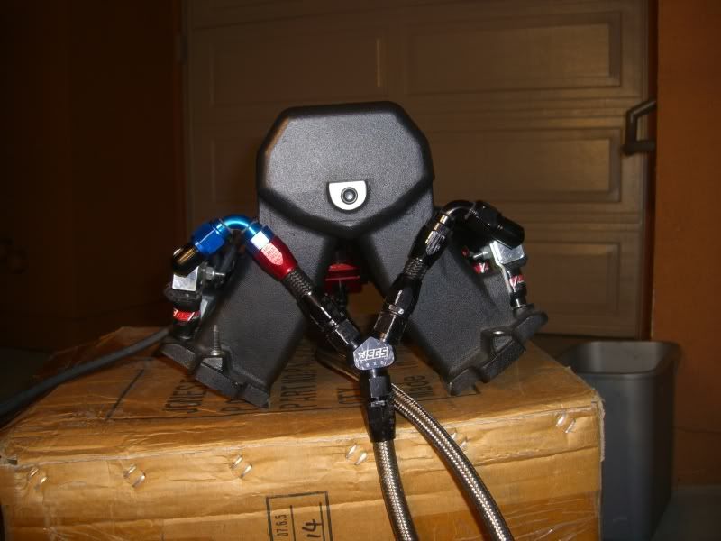
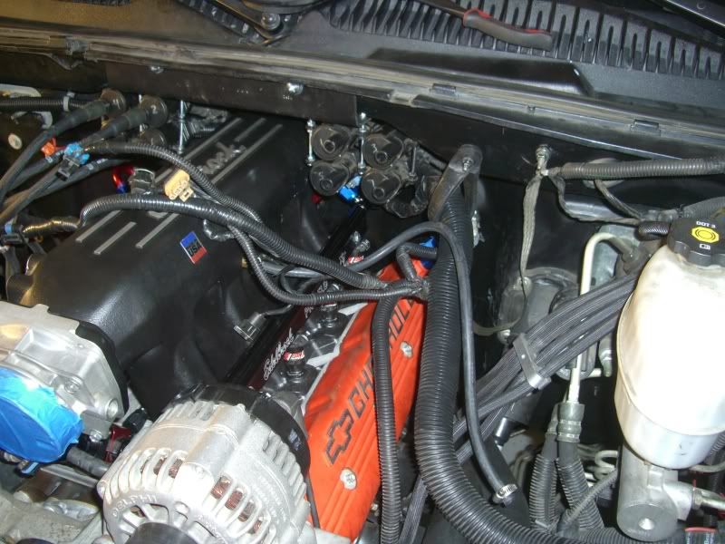
Got some stuff accomplished today!!! I started by painting a set of valve covers I've been looking to use. I bought them on here from a guy, they were Green  and not exactly what I wanted to see in my engine bay. I had a few cans of spray paint and I accidentally grabbed the wrong color, and after realizing my mistake, I said F$%& it and kept painting!
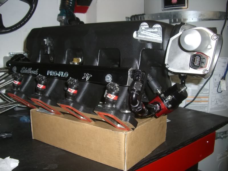
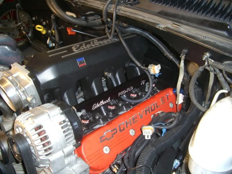
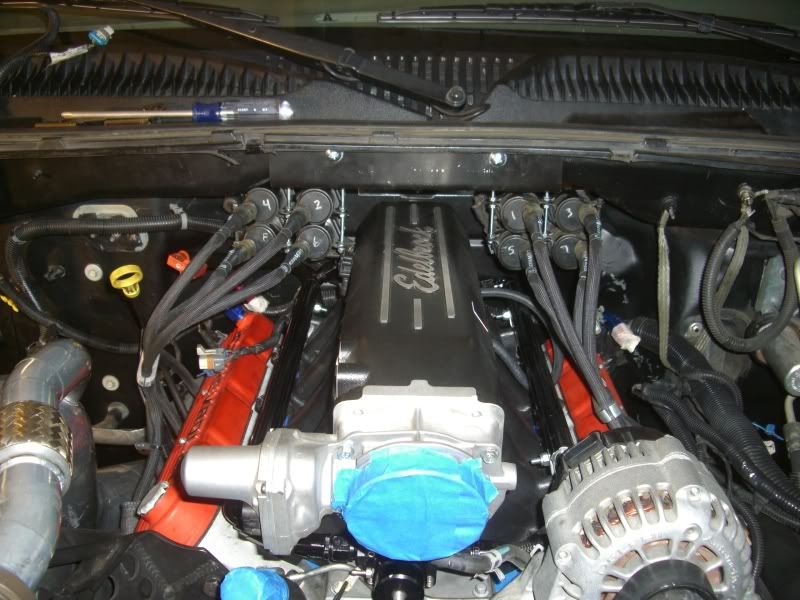
When I was done...I think it ended up looking DAMN GOOD!!
What do you guys think??
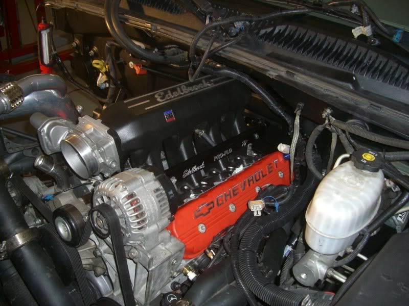
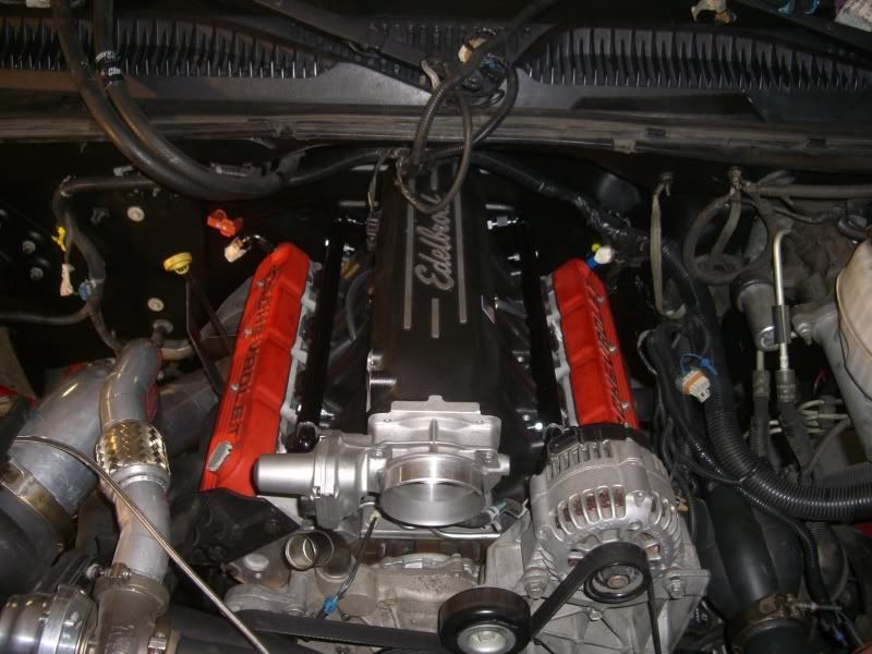
Wasn't the color I had planned on using but after seeing it installed, I really like it!!
Also, I haven't run the routing on it yet but as you can see, there are two -8 AN bungs welded into them, I've got a few left-over fuel fittings and am gonna route those to a vacuum pump and see if I can't pull a massive suction on the crankcase!!
Do you guys think I need to go to a catch can first before I route it to a vacuum pump? I'd like to go straight from the valve covers to the pump and call it good. Don't care so much about the loss of oil really, I just don't want to be sucking too much oil out of the engine to where it causes issues.
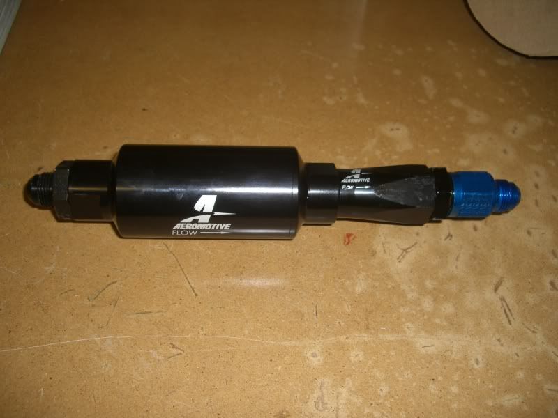
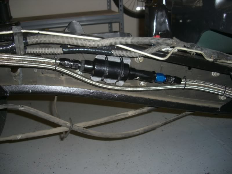
So anyways, I also found a check valve from a prior build, it was -10AN so I ordered some reducers so I could run it with my -8AN line. Figured while I was at it I would get a fuel filter (hadn't even crossed my mind but I'm glad I thought of it at the last second). Both came in the mail today and this is what it looks like all fitted...
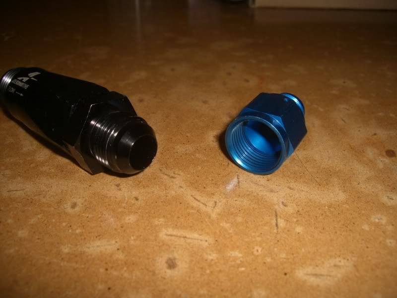
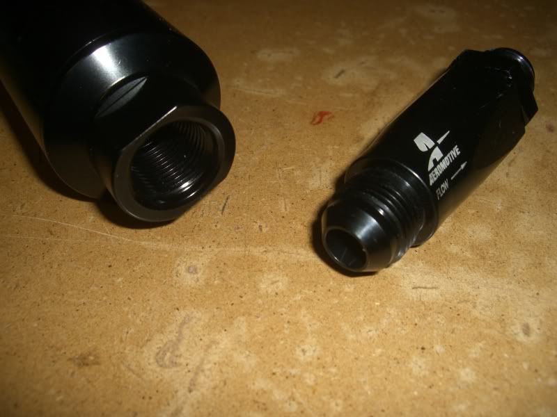
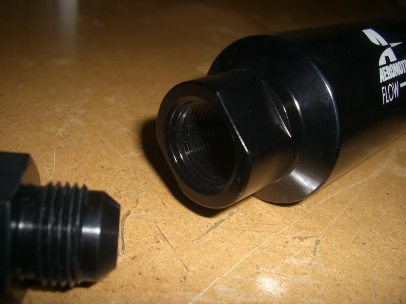
I'm a little worried about them sealing, I know some fittings use O-rings and other don't, not sure which is used when, but I guess when I first run the pump I'll find out if I have any leaks. I tighten down on all my fuel fittings as much as I can without damaging anything because fuel leaks **** me off. Anyone have any opinions on whether these need O-ring fittings or are the ones that I have ok? Here's a closer shot of them...
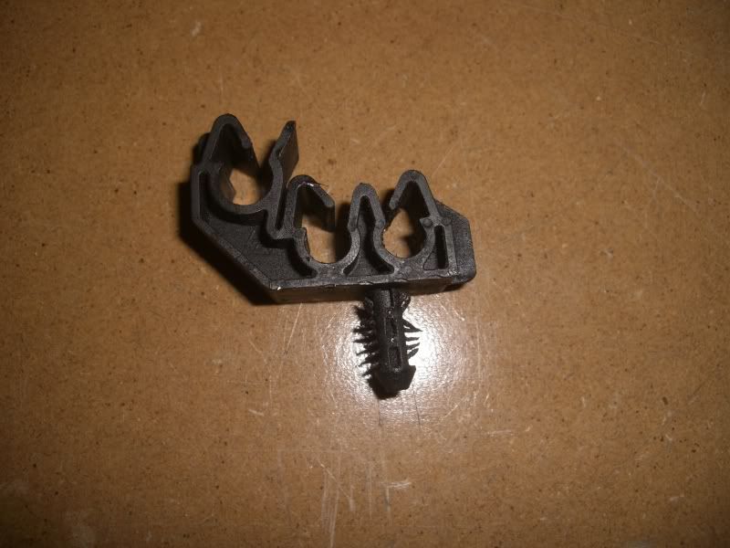
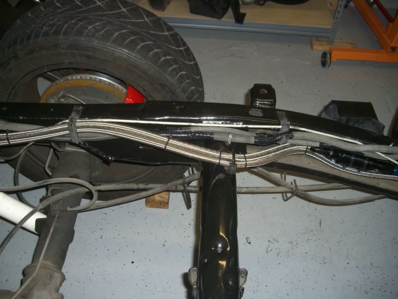
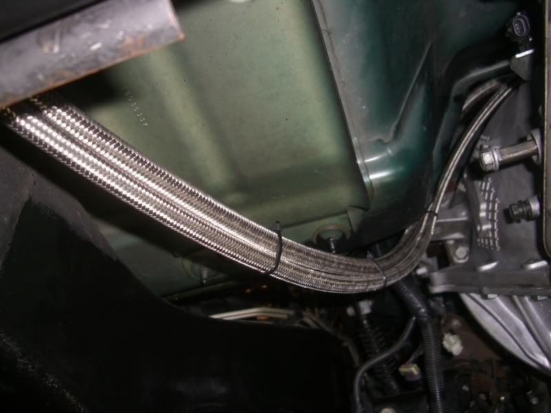
Anyways, I also ran a few fuel lines, still waiting on injectors before I can actually finish my fuel lines but I got started on them, while running them up the frame I decided to re-use on the the stock fuel line clips and modify it.
Here's before...
And here's after...
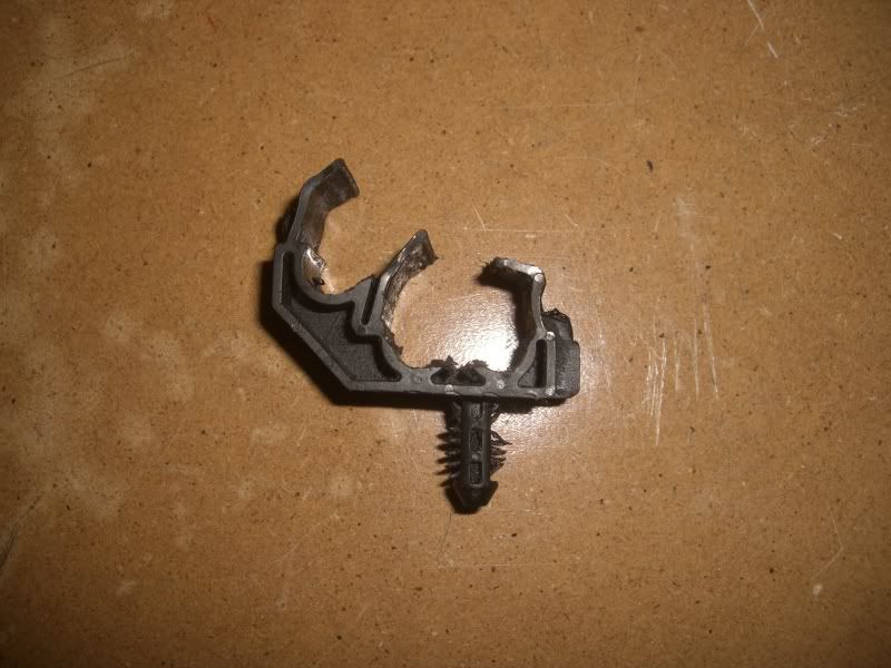
Now it can hold a -8 supply and a -6 return. I'll probably zip-tie the top of it so that the lines can't pop out but now I can re-use the stock fuel line locations.
I also did some wiring today, I extended my fuel bucket connectors. Needed 5 extra feet of wiring when all was said and done, here's them extended...
And then Wire-loomed, and tucked up along the frame rails...
I still have to wire in a relay-do-hickey that everyone's telling me to do and I also haven't wired the pump yet with the 10 gauge wiring. I left the power supply wires exposed so when I do get around to figuring out what it is I'm supposed to do, I don't have to uncover them again.
Anyone have any pics of exactly what it is I'm supposed to do here with the relay and what not? I need some tutoring!!
Here's where I'm at...
Take me to the promise land!!
and not exactly what I wanted to see in my engine bay. I had a few cans of spray paint and I accidentally grabbed the wrong color, and after realizing my mistake, I said F$%& it and kept painting! When I was done...I think it ended up looking DAMN GOOD!!
What do you guys think??
Wasn't the color I had planned on using but after seeing it installed, I really like it!!
Also, I haven't run the routing on it yet but as you can see, there are two -8 AN bungs welded into them, I've got a few left-over fuel fittings and am gonna route those to a vacuum pump and see if I can't pull a massive suction on the crankcase!!
Do you guys think I need to go to a catch can first before I route it to a vacuum pump? I'd like to go straight from the valve covers to the pump and call it good. Don't care so much about the loss of oil really, I just don't want to be sucking too much oil out of the engine to where it causes issues.
So anyways, I also found a check valve from a prior build, it was -10AN so I ordered some reducers so I could run it with my -8AN line. Figured while I was at it I would get a fuel filter (hadn't even crossed my mind but I'm glad I thought of it at the last second). Both came in the mail today and this is what it looks like all fitted...
I'm a little worried about them sealing, I know some fittings use O-rings and other don't, not sure which is used when, but I guess when I first run the pump I'll find out if I have any leaks. I tighten down on all my fuel fittings as much as I can without damaging anything because fuel leaks **** me off. Anyone have any opinions on whether these need O-ring fittings or are the ones that I have ok? Here's a closer shot of them...
Anyways, I also ran a few fuel lines, still waiting on injectors before I can actually finish my fuel lines but I got started on them, while running them up the frame I decided to re-use on the the stock fuel line clips and modify it.
Here's before...
And here's after...
Now it can hold a -8 supply and a -6 return. I'll probably zip-tie the top of it so that the lines can't pop out but now I can re-use the stock fuel line locations.
I also did some wiring today, I extended my fuel bucket connectors. Needed 5 extra feet of wiring when all was said and done, here's them extended...
And then Wire-loomed, and tucked up along the frame rails...
I still have to wire in a relay-do-hickey that everyone's telling me to do and I also haven't wired the pump yet with the 10 gauge wiring. I left the power supply wires exposed so when I do get around to figuring out what it is I'm supposed to do, I don't have to uncover them again.
Anyone have any pics of exactly what it is I'm supposed to do here with the relay and what not? I need some tutoring!!
Here's where I'm at...
Take me to the promise land!!

TECH Fanatic
Joined: Aug 2005
Posts: 1,004
Likes: 0
I think it looks good. I cant say i have an answer about your vacuum pump question but i would think that on the bottom of the valve cover where your fittings are you should have baffles. Is there some there already? The fuel line check valve, the end that goes into the filter iirc needs an o-ring unless, and i dont think so, inside the filter is a JIC end (tapered). The blue fitting to the other adapter fitting on the outlet of the filter will seal fine (JIC). I dont recall my aeromotive filters have that taper inside them. I am pretty positive they had o-rings.
Thread Starter
TECH Senior Member
iTrader: (8)
Joined: Jan 2007
Posts: 13,845
Likes: 0
From: Here and sometimes there too.
There are no baffles inside those valve covers, I checked for that and noticed there were none. I know that it's not ideal but I figured it would work just as well. Should I think about adding some?
I'll double check both ends of the filter to see if they are tapered inside. Thanks for the heads up.
I'll double check both ends of the filter to see if they are tapered inside. Thanks for the heads up.
TECH Fanatic
Joined: Aug 2005
Posts: 1,004
Likes: 0
The reason i mentioned about the baffles is i would think you would vacuum alot of oil out of the motor. I may be wrong though as i don't have any first hand experience. I would think that you would want to pull the pressure out without pulling and oil that will be splashing around in the cover. Looking at the filter again it looks like it is an ORB (o-ring boss). Just get the correct o-ring for the check valve and you should be good to go. I dont think it would leak. the only thing i would think may cause a problem would be the JIC end on the check valve going into the filter. I doubt it though. May want to put this question in the fuel section. Build is coming along nice.
Thread Starter
TECH Senior Member
iTrader: (8)
Joined: Jan 2007
Posts: 13,845
Likes: 0
From: Here and sometimes there too.
I am worried about the lack of baffles for the same reason, I might add some later but for now, just so I can move on to other things I'm gonna run with it the way it is, I should also be testing the pump here at the end of the week to check for leaks so I'll revisit the fitting issues then as well.
So a few things today...
Got this done...
+
+
+
=
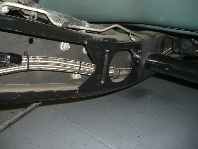
I also finished all the fuel lines. Again I'm gonna revisit the fuel filter connections after I test the fuel pump and what not. My guess would be it's gonna need some new fittings. Anyways, here's what I came up with...
And then up to the engine...
So aside from that, I have two questions!
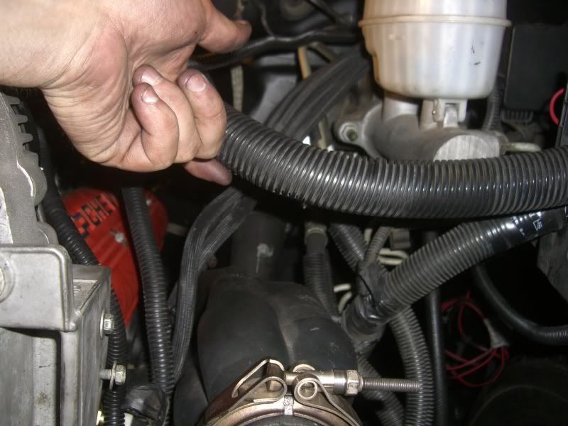
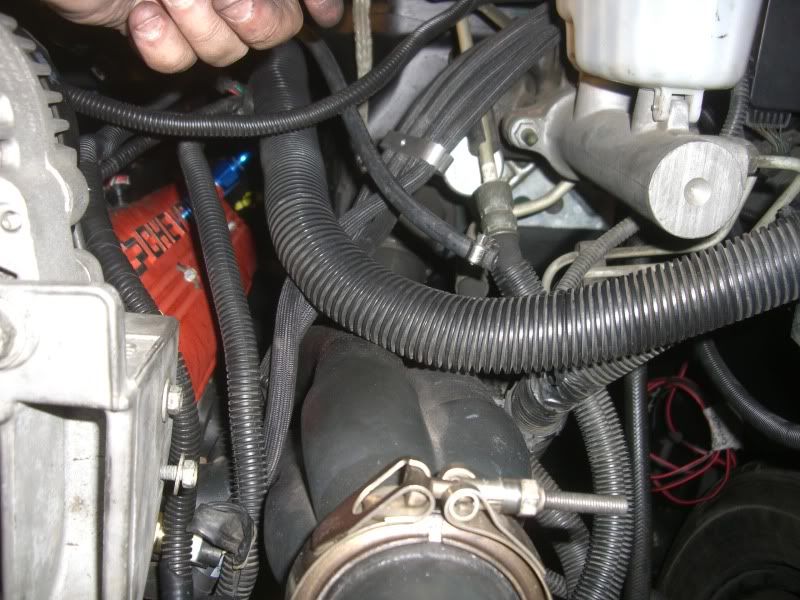
First being, where does this plastic harness clip "clip in"!??
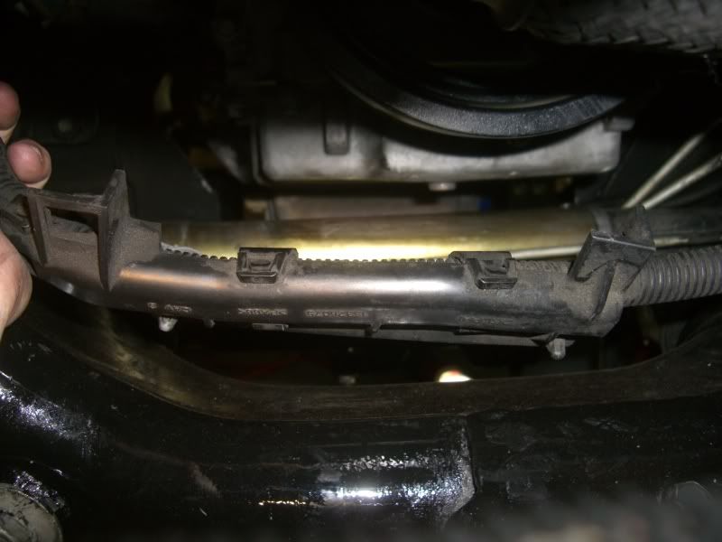
I feel like an idiot because it's on the tip of my brain but I just can't recall where exactly it goes. It's the wiring harness for the starter that wraps around the front of the oil pan/block.
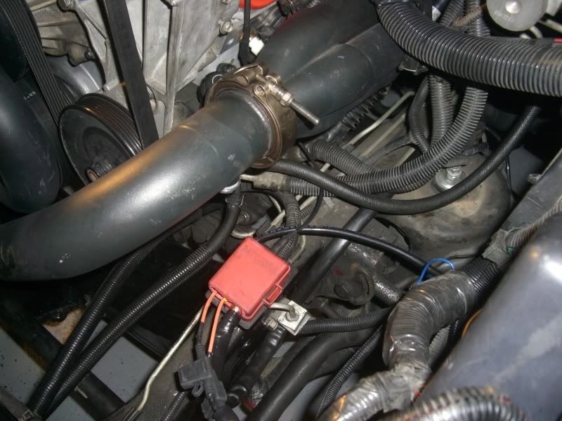
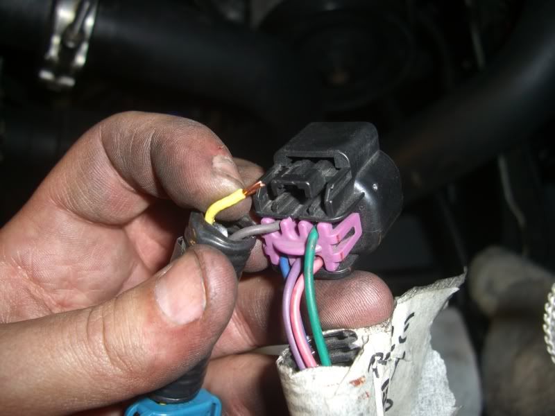
Second question is, anyone have any idea on how to remove a stuck harness plug?? This is the plug in question, it's part of the tranny control module...
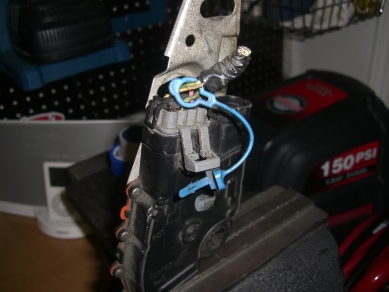
I'm affraid I'm gonna snap or break it if I try to pry it out anymore, I've tried pliers, screw-drivers, channel locks...anyone have any other ideas? WD-40 maybe?
So a few things today...
Got this done...
+
+
+
=
I also finished all the fuel lines. Again I'm gonna revisit the fuel filter connections after I test the fuel pump and what not. My guess would be it's gonna need some new fittings. Anyways, here's what I came up with...
And then up to the engine...
So aside from that, I have two questions!
First being, where does this plastic harness clip "clip in"!??
I feel like an idiot because it's on the tip of my brain but I just can't recall where exactly it goes. It's the wiring harness for the starter that wraps around the front of the oil pan/block.
Second question is, anyone have any idea on how to remove a stuck harness plug?? This is the plug in question, it's part of the tranny control module...
I'm affraid I'm gonna snap or break it if I try to pry it out anymore, I've tried pliers, screw-drivers, channel locks...anyone have any other ideas? WD-40 maybe?
TECH Fanatic
Joined: Aug 2005
Posts: 1,004
Likes: 0
Seen that harness plug problem about a thousand times. What a pain in the ***. I have had lots that could not be saved. Try using a heat gun to loosen up the glue or whatever the crap is inside the switch. Heat up around the plug, gently push it out with a standard screwdriver. dont burn yourself.
Thread Starter
TECH Senior Member
iTrader: (8)
Joined: Jan 2007
Posts: 13,845
Likes: 0
From: Here and sometimes there too.
Thanks SSZ, I decided to solder the clip back onto the harness without removing the clip from the module, figured it would damage the plug the least. Thanks! 
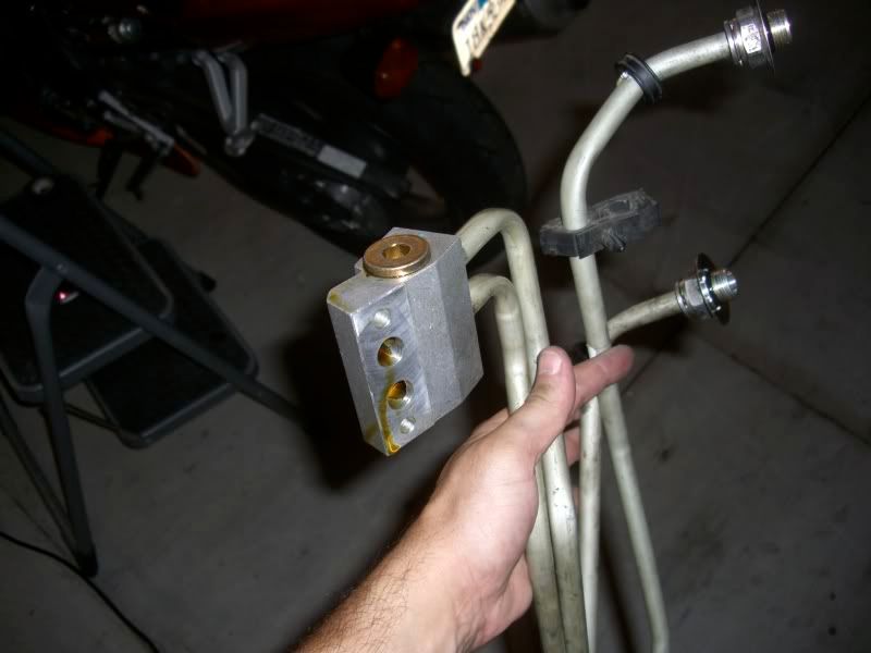
I'm looking for an oil cooler block that has an additional outlet port that I can use to run oil supply to my turbo while retaining the engine oil cooler lines.
You guys think this will work alright??
http://www.lingenfelter.com/mm5/merc...gory_Code=C186
If so, Looks like I'll be needing to run new coolant lines from the block to the radiator, what fittings am I gonna need that plug into the radiator? This is what those fittings look like on the other end of the coolant lines that fit into the radiator. I'd love to be able to re-use those lines but doubt that would be possible. I know those fittings are two part fitting too, which would be easier to make it adapt to the radiator, the threaded ones or the clip on ones?
I'm looking for an oil cooler block that has an additional outlet port that I can use to run oil supply to my turbo while retaining the engine oil cooler lines.
You guys think this will work alright??
http://www.lingenfelter.com/mm5/merc...gory_Code=C186
If so, Looks like I'll be needing to run new coolant lines from the block to the radiator, what fittings am I gonna need that plug into the radiator? This is what those fittings look like on the other end of the coolant lines that fit into the radiator. I'd love to be able to re-use those lines but doubt that would be possible.
I know those fittings are two part fitting too, which would be easier to make it adapt to the radiator, the threaded ones or the clip on ones? LS1 Tech Stories
The Best V8 Stories One Small Block at Time

Gas Monkey Built a 6-Wheel Ferrari Testarossa With a Corvette LT4 Engine
Verdad Gallardo
7 Most Reliable High-Performance Engines GM Has Ever Built
Verdad Gallardo
Amazing '71 Camaro Restomod Is Modern Muscle Car Under the Skin
Verdad Gallardo
6 Common C5 Corvette Failures and What's Involved In Repairing Them
Pouria Savadkouei
Retro Modern Bandit Pontiac Trans AM Comes With Burt Reynolds' Autograph
Verdad Gallardo
Top 10 Greatest Cadillac V Series Performance Models Ever, Ranked
Pouria Savadkouei
Top 10 Most Powerful Chevy Trucks Ever Made!

Hennessey's New Supercharged Silverado ZR2 Has 700 HP
Verdad Gallardo
Coachbuilt N2A Anteros Is an LS2-Powered C6 Corvette In Italian Clothes
Verdad Gallardo Thread Starter
TECH Senior Member
iTrader: (8)
Joined: Jan 2007
Posts: 13,845
Likes: 0
From: Here and sometimes there too.
Soooo...I got a new battery tray...
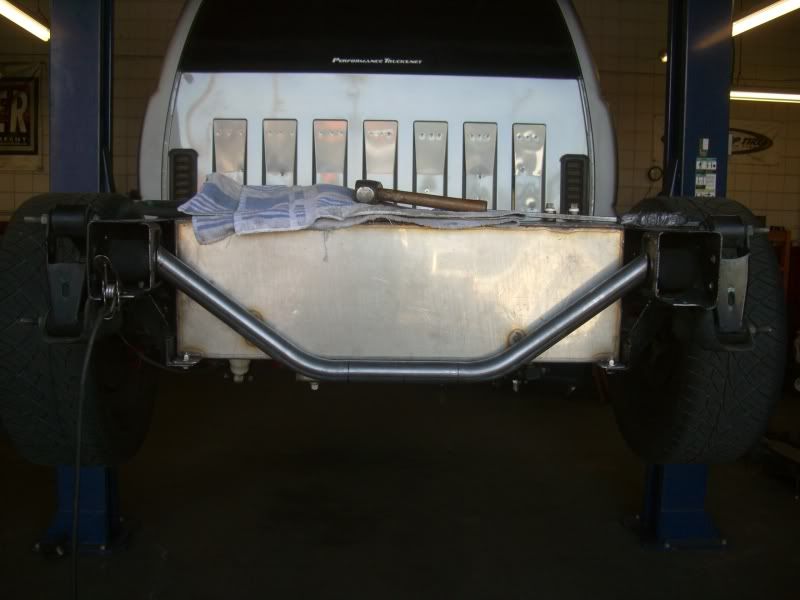
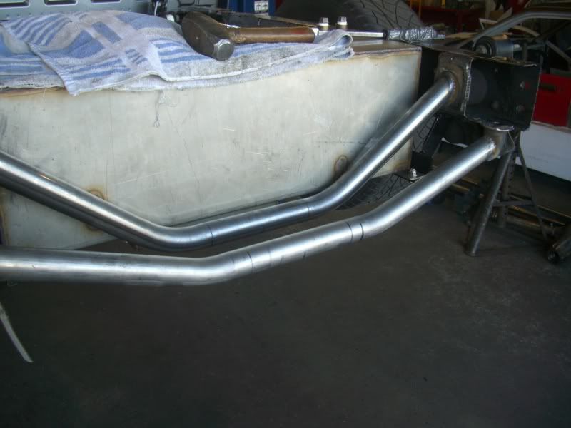
Got my truck towed to a buddy's shop. He builds cages and road racing cars, so he's pretty good with a mandrel bender! Anyways, we tried to figure something out that would stiffen up the rear frame between the hangers as well as provide me with a place to locate the battery. So this is how it came to be...
Started off by boxing in the location where the previous crossmember used to be...
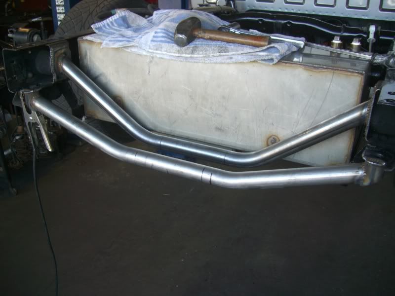
Installed the first crossmember...
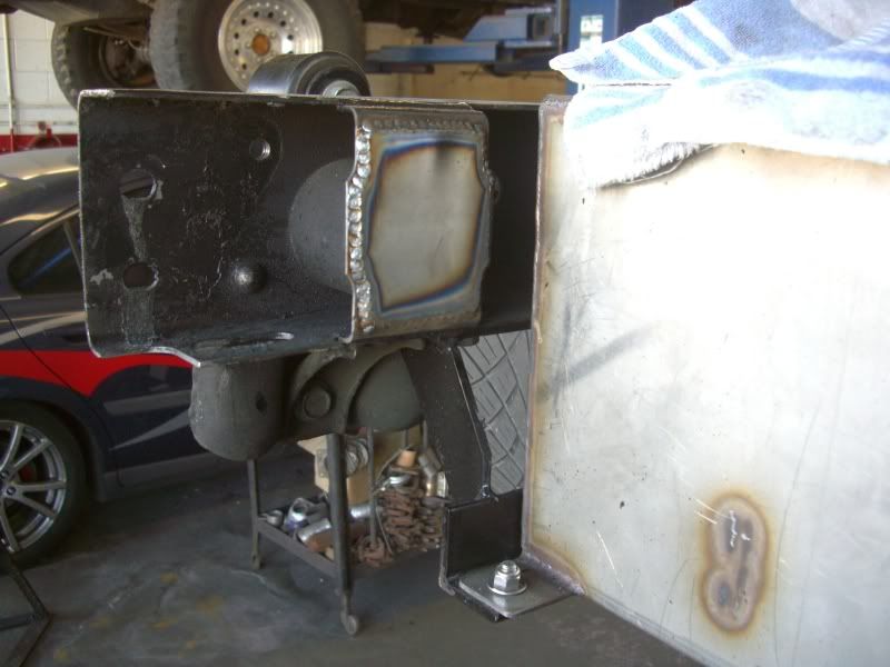
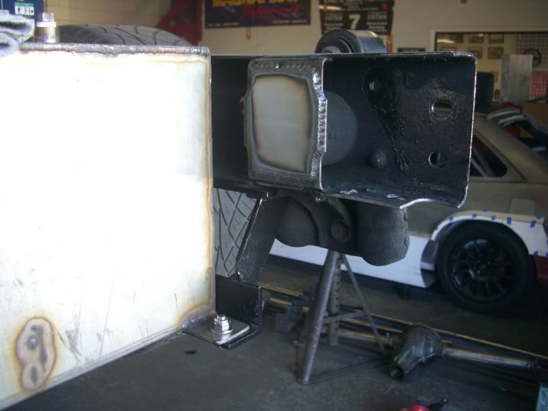
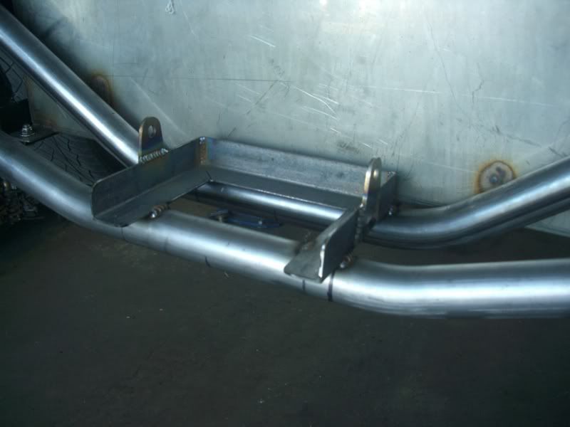
Followed by the second, you'll notice he welded cups onto the bottom of the frame rails, and welded the crossmember there. The cups are hollow so as to allow access to the bolts that secure the bumper in place...
And finished up by building a small battery tray...
Here's what it looks like with the bumper in place and a battery sitting in the tray...
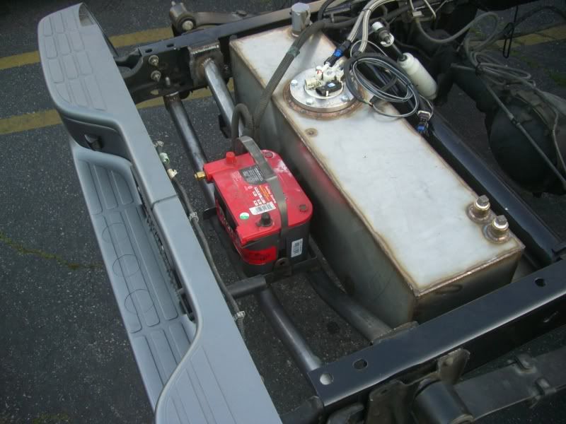
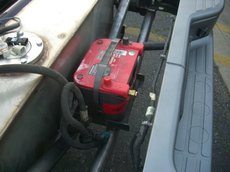
I plan on running remote leads into the bumper so as to do an easy jump start if need be. Only drawback to this is that I'll have to pull the bumper off to swap out batteries. Ahh well...
I think that should do the trick for now. Now I can get to wiring this truck up proper and moving on to other things, hopefully.
Got my truck towed to a buddy's shop. He builds cages and road racing cars, so he's pretty good with a mandrel bender! Anyways, we tried to figure something out that would stiffen up the rear frame between the hangers as well as provide me with a place to locate the battery. So this is how it came to be...
Started off by boxing in the location where the previous crossmember used to be...
Installed the first crossmember...
Followed by the second, you'll notice he welded cups onto the bottom of the frame rails, and welded the crossmember there. The cups are hollow so as to allow access to the bolts that secure the bumper in place...
And finished up by building a small battery tray...
Here's what it looks like with the bumper in place and a battery sitting in the tray...
I plan on running remote leads into the bumper so as to do an easy jump start if need be. Only drawback to this is that I'll have to pull the bumper off to swap out batteries. Ahh well...
I think that should do the trick for now. Now I can get to wiring this truck up proper and moving on to other things, hopefully.
Thread Starter
TECH Senior Member
iTrader: (8)
Joined: Jan 2007
Posts: 13,845
Likes: 0
From: Here and sometimes there too.
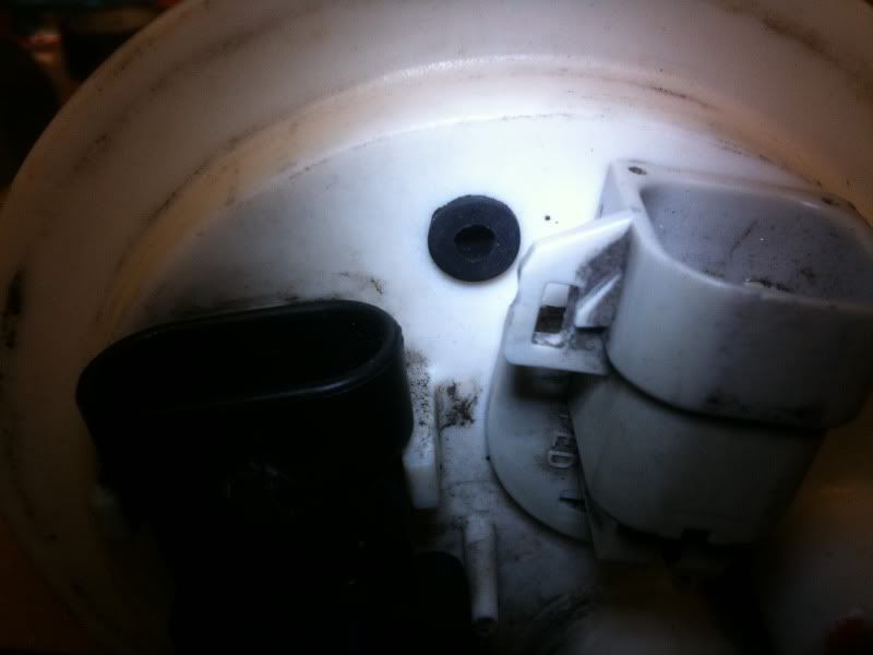
I "gutted" the middle line (I think it used to be the EVAP) and am gonna use that as a vent.
Here's what's left of the check valve that is part of that line...
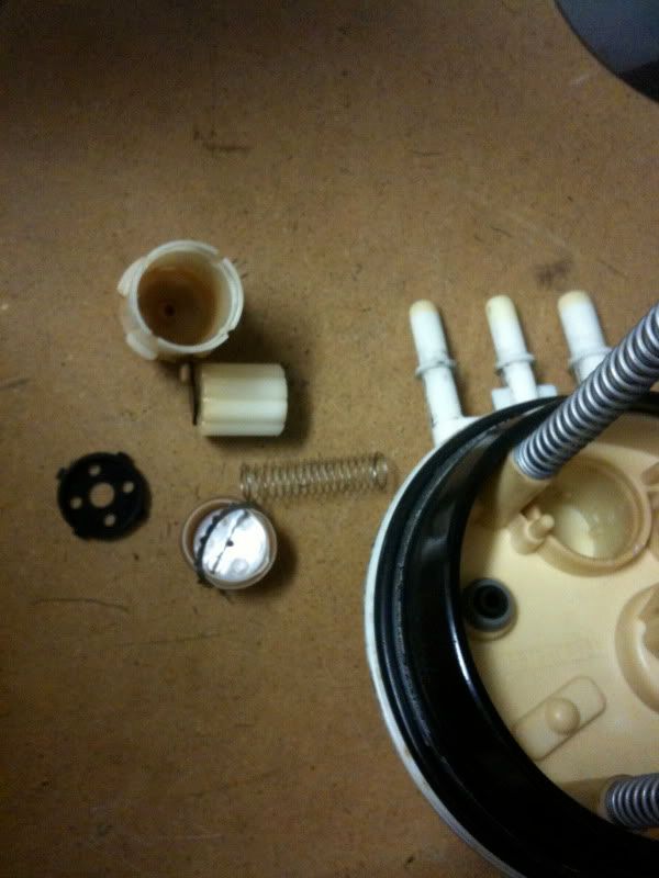
And the hole that it occupied...
I also drilled out the line/pipe to enlarge the inner diameter so that it would not be so small as to allow the tank to pressurize...
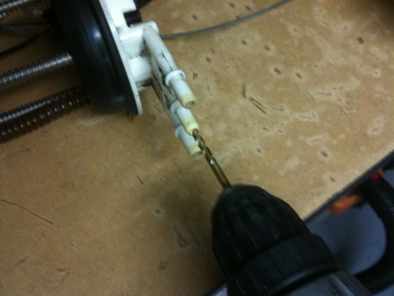
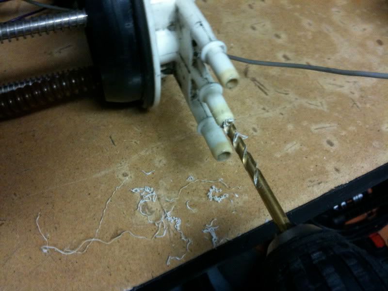
Now it's about 1/4" of so.
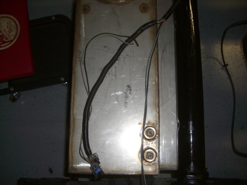
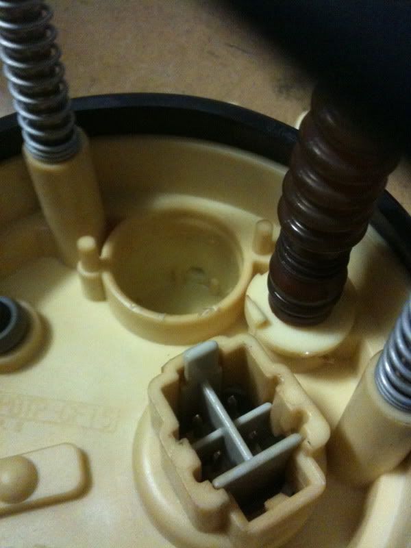
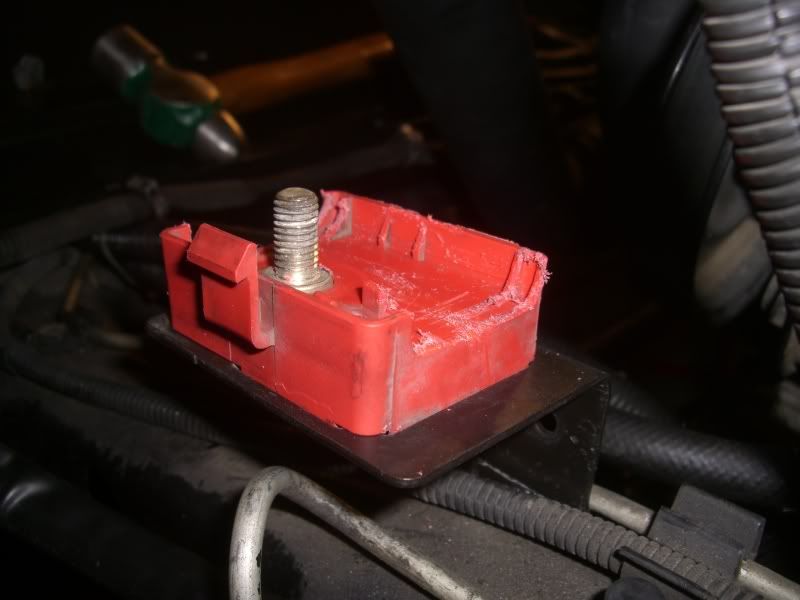
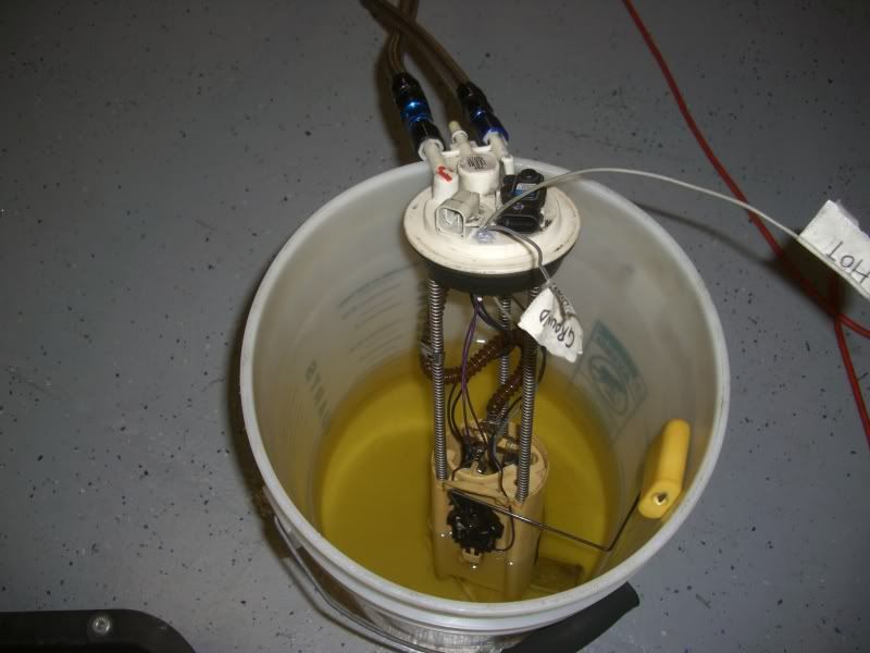
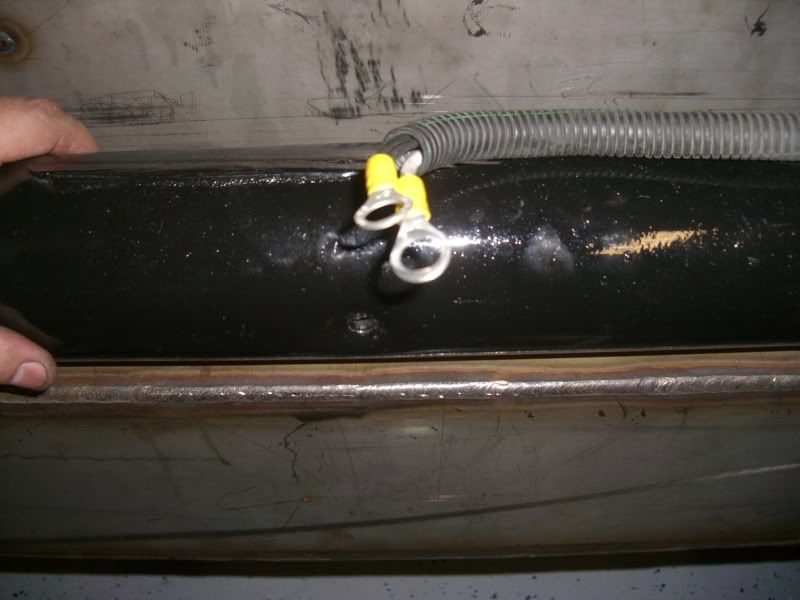
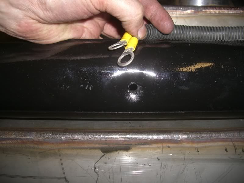
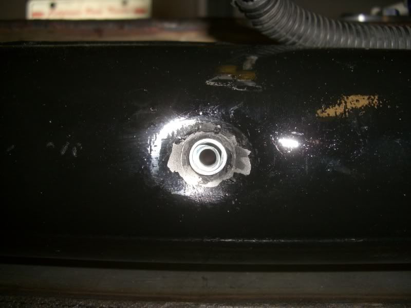
I also drilled a hole through the top of the bucket and installed a grommet...
ran the wires...
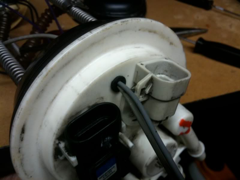
And haven't decided how I'm gonna seal it. I have plastic welder, JB weld and Gray RTV, I'll probably do a combination of them tomorrow.
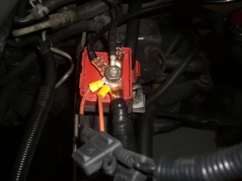
Also re-wired the bucket so that the stock wiring works on one pump, the other pump will be activated when I switch to Hi on the boost controller.
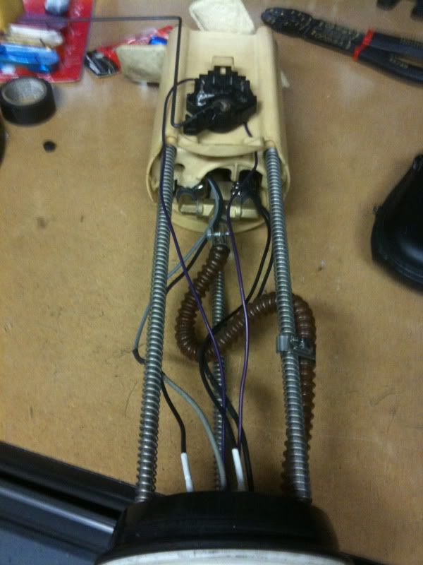
I hope I didn't mix up the plug wires!!
I'm gonna flush out the system tomorrow morning before doing final assembly. I also ran the power supply from the aft mounted battery all the way up into the engine bay. I ran it inside the frame rail inside some Irrigation tubing to protect it. I think it looks really well hidden and kinda stock. I'll take pictures of it tomorrow when I get some more time.
Here's what's left of the check valve that is part of that line...
And the hole that it occupied...
I also drilled out the line/pipe to enlarge the inner diameter so that it would not be so small as to allow the tank to pressurize...
Now it's about 1/4" of so.
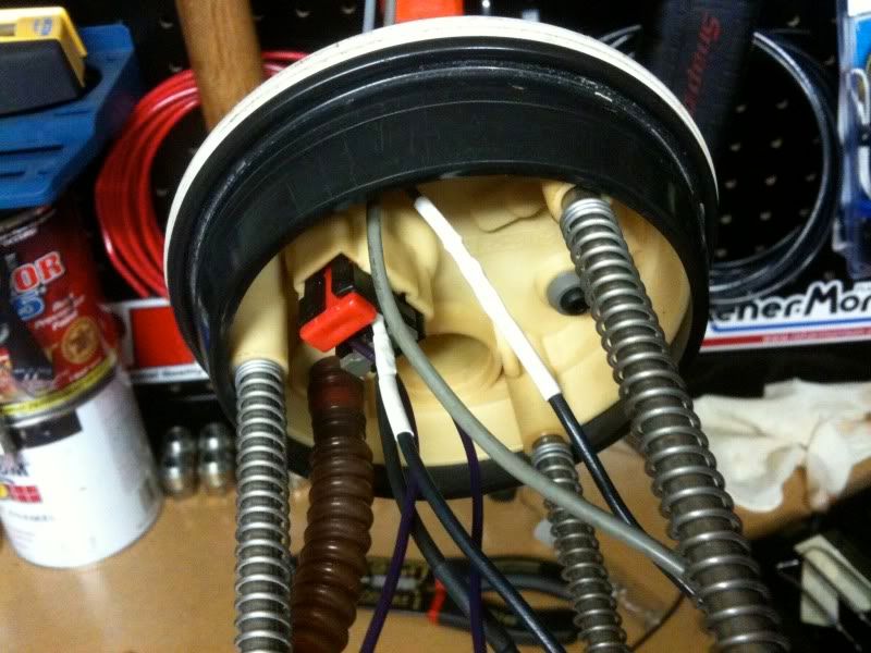
I also drilled a hole through the top of the bucket and installed a grommet...
ran the wires...
And haven't decided how I'm gonna seal it. I have plastic welder, JB weld and Gray RTV, I'll probably do a combination of them tomorrow.
Also re-wired the bucket so that the stock wiring works on one pump, the other pump will be activated when I switch to Hi on the boost controller.
I hope I didn't mix up the plug wires!!
I'm gonna flush out the system tomorrow morning before doing final assembly. I also ran the power supply from the aft mounted battery all the way up into the engine bay. I ran it inside the frame rail inside some Irrigation tubing to protect it. I think it looks really well hidden and kinda stock. I'll take pictures of it tomorrow when I get some more time.
Last edited by Spoolin; Feb 1, 2011 at 02:19 AM.
Thread Starter
TECH Senior Member
iTrader: (8)
Joined: Jan 2007
Posts: 13,845
Likes: 0
From: Here and sometimes there too.
Update time!!
I'm at the point in the build where it's more fabrication than it is anything else and when it comes to fabrication...well I don't have the tools for it so that really slows me down.
Anywho, I ran the battery cable from the back of the truck all the way up front into the engine bay. I ran it inside the frame rails 95% of the way and wrapped it inside some irrigation tubing after the advice of a friend. Works like wire-loom only better and more flexible. Only drawback is instead of using welding cable I ended up using commercial grade wiring that is like 6 strand 0 gauge. Stuff is super stiff and hard to move and I spent alot of time getting it to where I wanted it. Anyways, I needed to re-locate the Junciton box bracket since I moved my PCM and my hot parts were in the way, so instead of building a new bracket, I bent mine to fit!! Here's the new location for it...
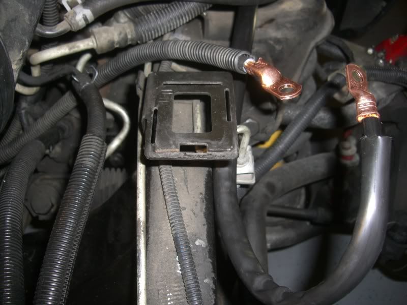
I was able to get most of the necessary wires onto the bolt. My only regret is that I wasn't able to find the stock GM connector anywhere that crimps onto the main cable without cutting it so as to allow it to run un-impeded to the starter yet still supply power to the bolt. I had to cut the cable and crimp on some eyelet terminals.
I still have the amp power supply to hook up but I'm gonna run it back to the battery since there isn't enough room on the common stud for it.
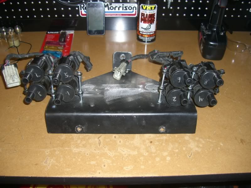
Next I moved onto the coil packs!
Took me the better part of 3 days to hunt down the tools I needed and the pieces that were required to make this happen. Anyways, here's the mounting bracket...
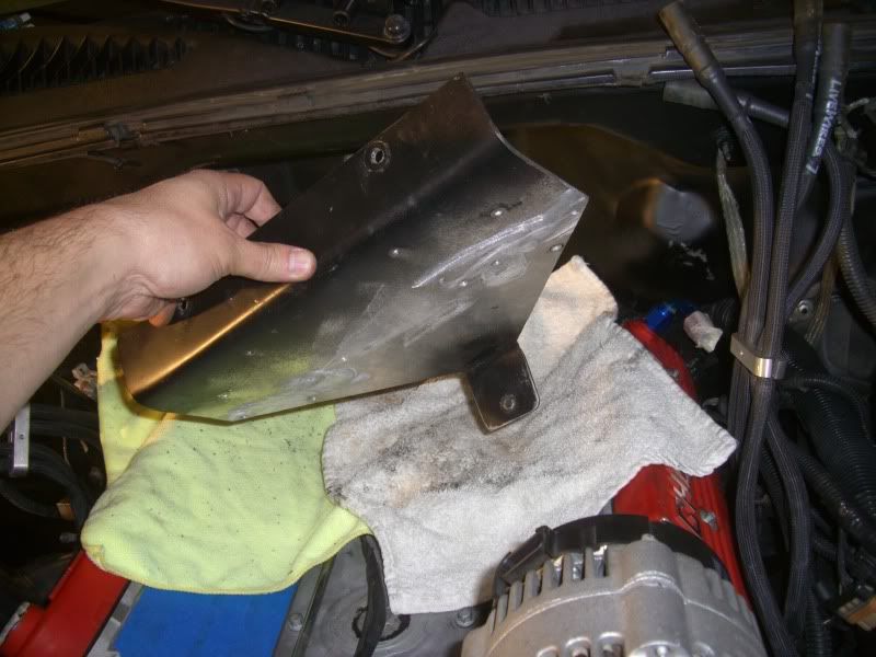
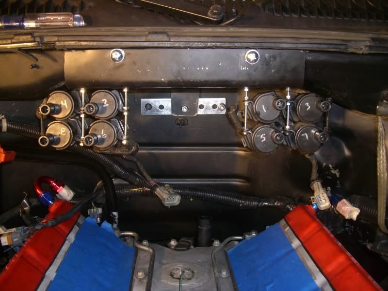
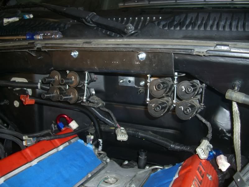
I mounted it up against the back of the fire-wall like so...
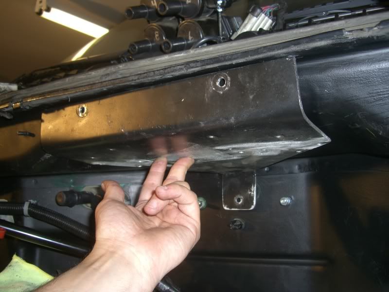
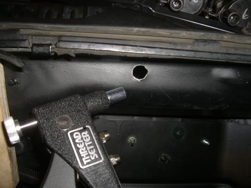
To mount it I bought a NutSert tool and went ahead and drilled a few holes in the fire-wall...BIG HOLES, and inserted two of them to support the bracket!!
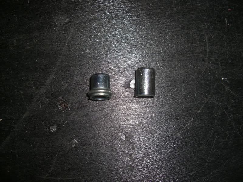
Here's what the threaded bolt rivet things look like when crimped into place...
Here's the coil packs assembled on the bracket so that my big *** intake would clear it! (This is the only time I've regretted getting this intake. If I had a Vic Jr. or the truck intake I would of been able to keep my heater hoses and what not.
Anyways...
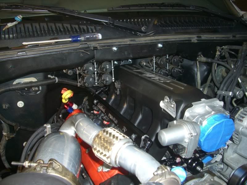
Coil wires run...
There's still a few things I need to finish up, I wanted to re-paint alot of it but unfortunetly I'd rather get this thing done and on the road at this point since I'm kinda of under the gun to finish this now.
I'm at the point in the build where it's more fabrication than it is anything else and when it comes to fabrication...well I don't have the tools for it so that really slows me down.
Anywho, I ran the battery cable from the back of the truck all the way up front into the engine bay. I ran it inside the frame rails 95% of the way and wrapped it inside some irrigation tubing after the advice of a friend. Works like wire-loom only better and more flexible. Only drawback is instead of using welding cable I ended up using commercial grade wiring that is like 6 strand 0 gauge. Stuff is super stiff and hard to move and I spent alot of time getting it to where I wanted it. Anyways, I needed to re-locate the Junciton box bracket since I moved my PCM and my hot parts were in the way, so instead of building a new bracket, I bent mine to fit!!
Here's the new location for it...I was able to get most of the necessary wires onto the bolt. My only regret is that I wasn't able to find the stock GM connector anywhere that crimps onto the main cable without cutting it so as to allow it to run un-impeded to the starter yet still supply power to the bolt. I had to cut the cable and crimp on some eyelet terminals.
I still have the amp power supply to hook up but I'm gonna run it back to the battery since there isn't enough room on the common stud for it.
Next I moved onto the coil packs!
Took me the better part of 3 days to hunt down the tools I needed and the pieces that were required to make this happen. Anyways, here's the mounting bracket...
I mounted it up against the back of the fire-wall like so...
To mount it I bought a NutSert tool and went ahead and drilled a few holes in the fire-wall...BIG HOLES, and inserted two of them to support the bracket!!
Here's what the threaded bolt rivet things look like when crimped into place...
Here's the coil packs assembled on the bracket so that my big *** intake would clear it! (This is the only time I've regretted getting this intake. If I had a Vic Jr. or the truck intake I would of been able to keep my heater hoses and what not.
Anyways...
Coil wires run...
There's still a few things I need to finish up, I wanted to re-paint alot of it but unfortunetly I'd rather get this thing done and on the road at this point since I'm kinda of under the gun to finish this now.
Last edited by Spoolin; Feb 5, 2011 at 02:06 AM.
Thread Starter
TECH Senior Member
iTrader: (8)
Joined: Jan 2007
Posts: 13,845
Likes: 0
From: Here and sometimes there too.
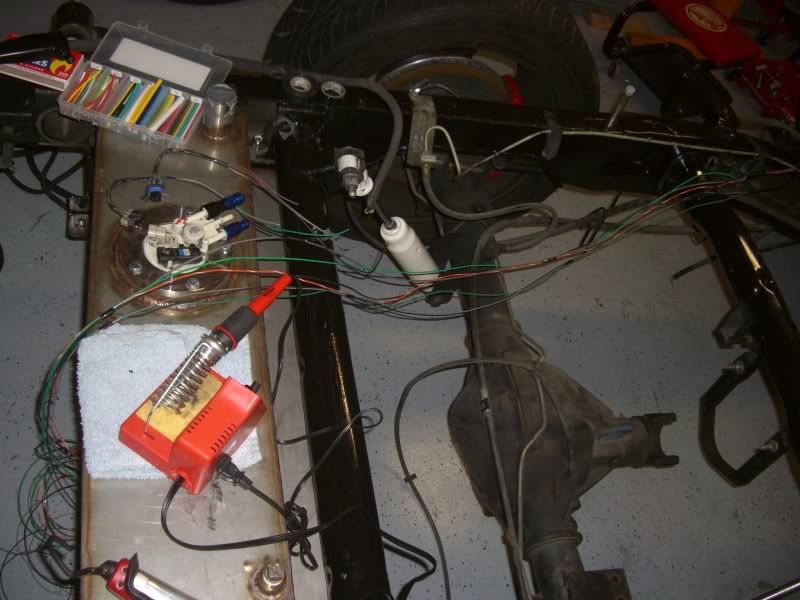
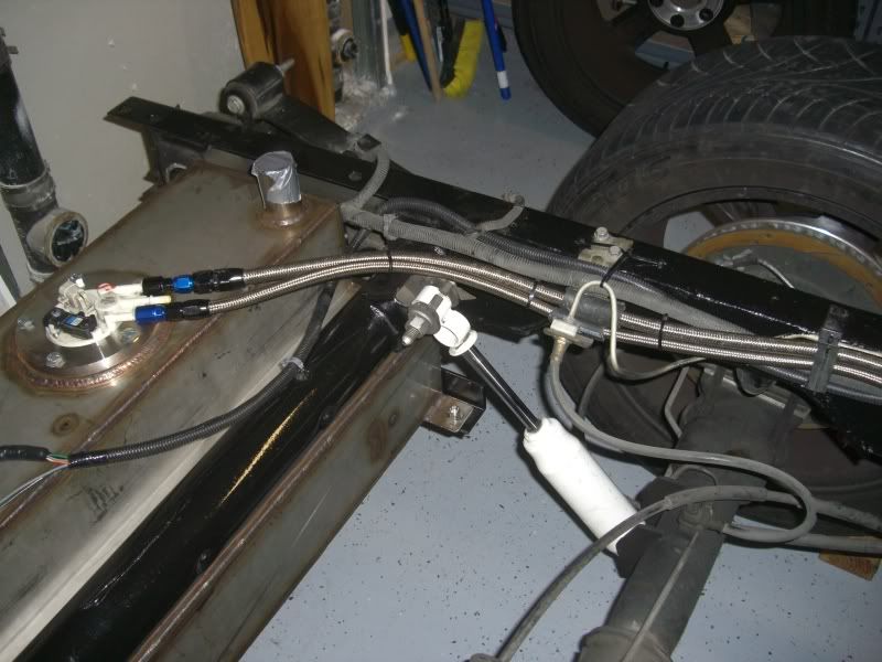
Next up was the fuel system. I wanted to charge the system to check for leaks as well as flush it out of any debris. I first flushed all the lines individually and then hooked them all up together and ran the whole system for about 3 minutes...

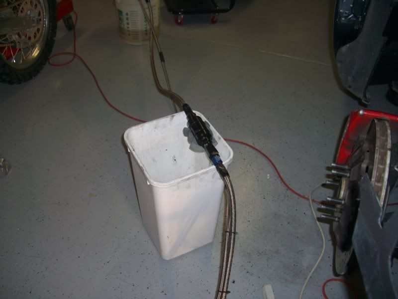
There was a bit of rubber junk from the hoses assembly that did get shot out. And I also found two leaks, one major, and the other minor. The major leak was just a question of tightening down some fittings, the smaller one requires me to get a new piece of hose. No biggie, just another set-back though. I should be ready to throw the intake back on for the final time hopefully this weekend and be done with the fuel system.
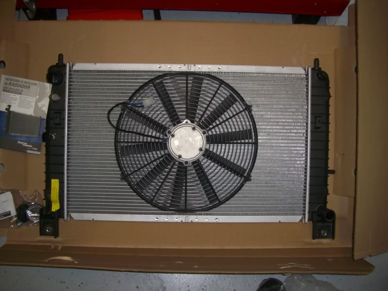
I also got my new radiator and fans today, they look so tiny!!!
There was a bit of rubber junk from the hoses assembly that did get shot out. And I also found two leaks, one major, and the other minor. The major leak was just a question of tightening down some fittings, the smaller one requires me to get a new piece of hose. No biggie, just another set-back though. I should be ready to throw the intake back on for the final time hopefully this weekend and be done with the fuel system.
I also got my new radiator and fans today, they look so tiny!!!
Thread Starter
TECH Senior Member
iTrader: (8)
Joined: Jan 2007
Posts: 13,845
Likes: 0
From: Here and sometimes there too.
Sweet!! Progress was made today! 
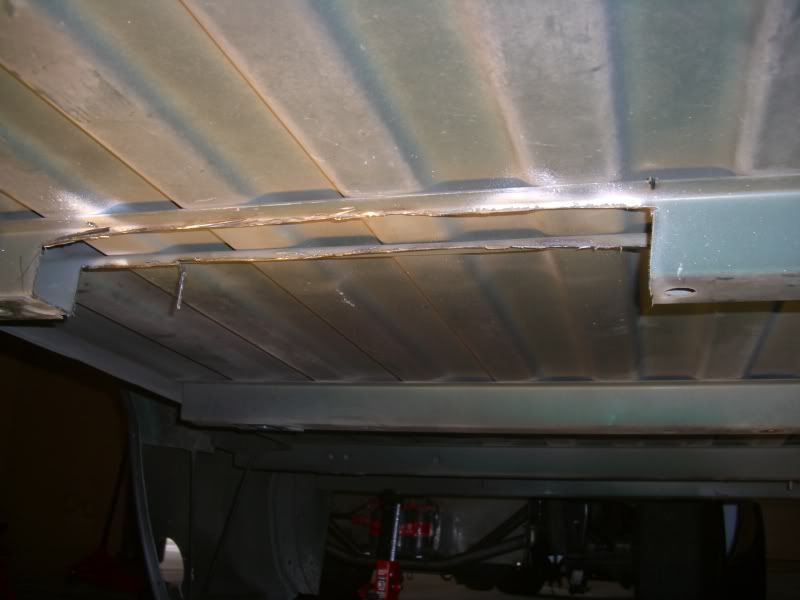
First, here's the carnage from yesterday...
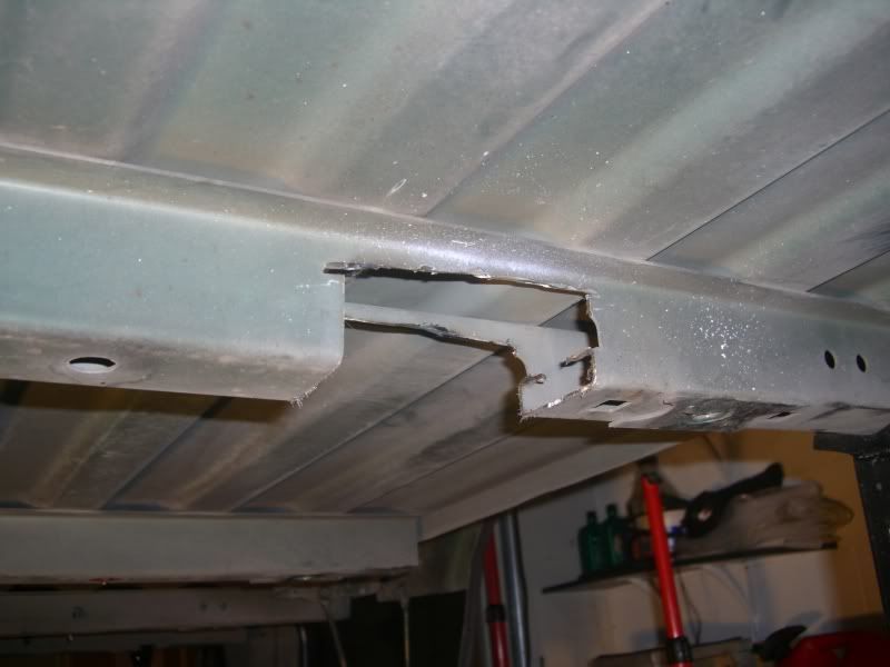
This is the last cross member under the bed closest to the bumper, looks like my payload capabilities have been affected!! I needed to cut it out so the filler and fuel bucket would clear, I've since cleaned up the cuts so they are smooth as a elephants ***...
And I cut this little section out so that my two extra bungs would have room as well once I decide what I'm gonna do with those eventually...
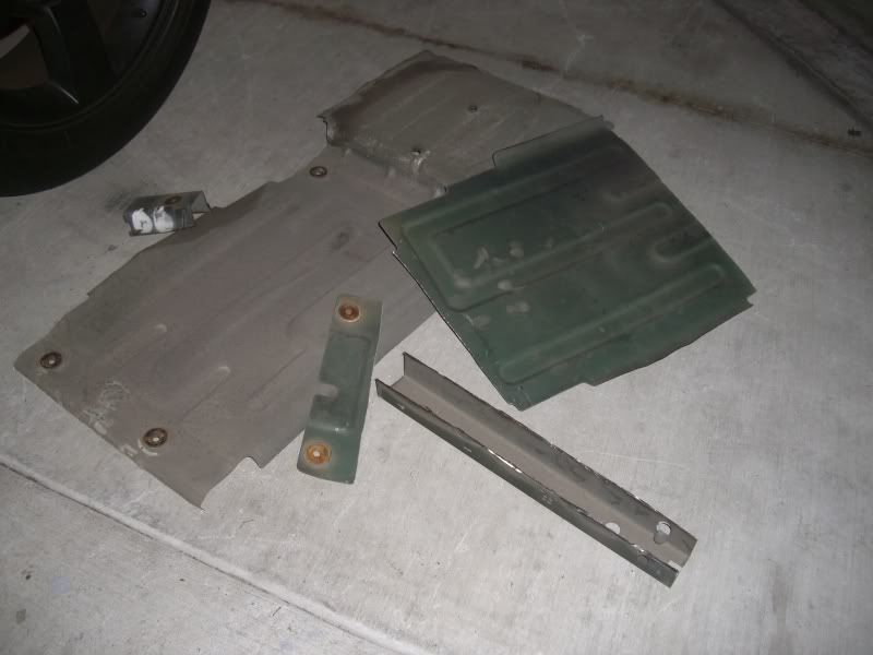
Here's part of a pile of all the heat shields and crossmembers that I cut-out. I had to drill the bolts out that holds the heat shields in place. This stupid job took me about 3-4 hours.
I also did some zip-tying of the harness up on the firewall so it's not out and all over the place...
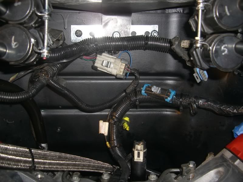
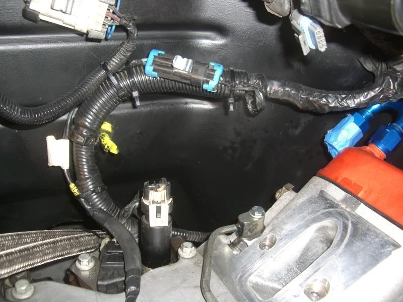
When I was fugging around with the wiring I found that my TB connector had a wire pop out I'm gonna have to fix that...
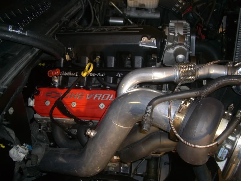
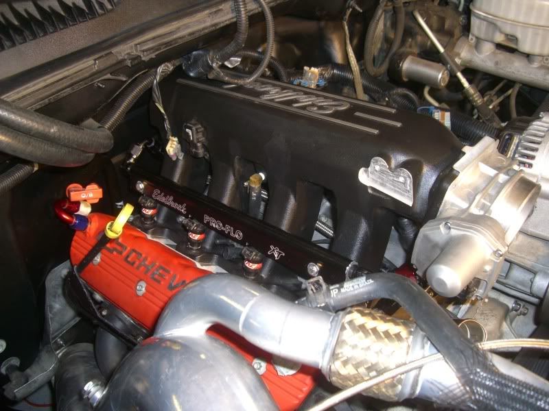
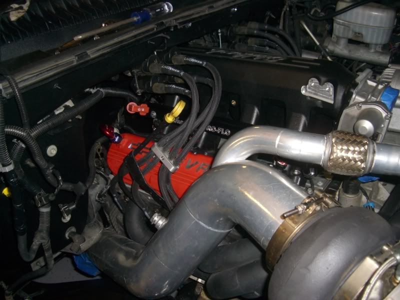
I dropped on my intake for the last time and Torqued it down. Ran the harness on the passenger side so it's all tucked away and mostly out of sight, so this side is pretty much finished...
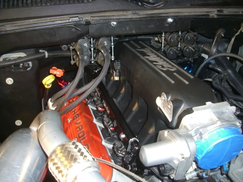
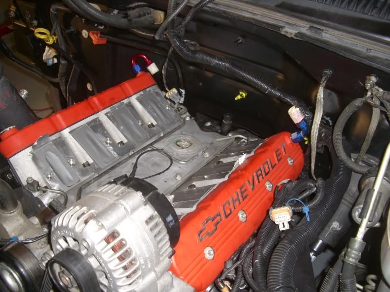
Here's the diver's side as of now...
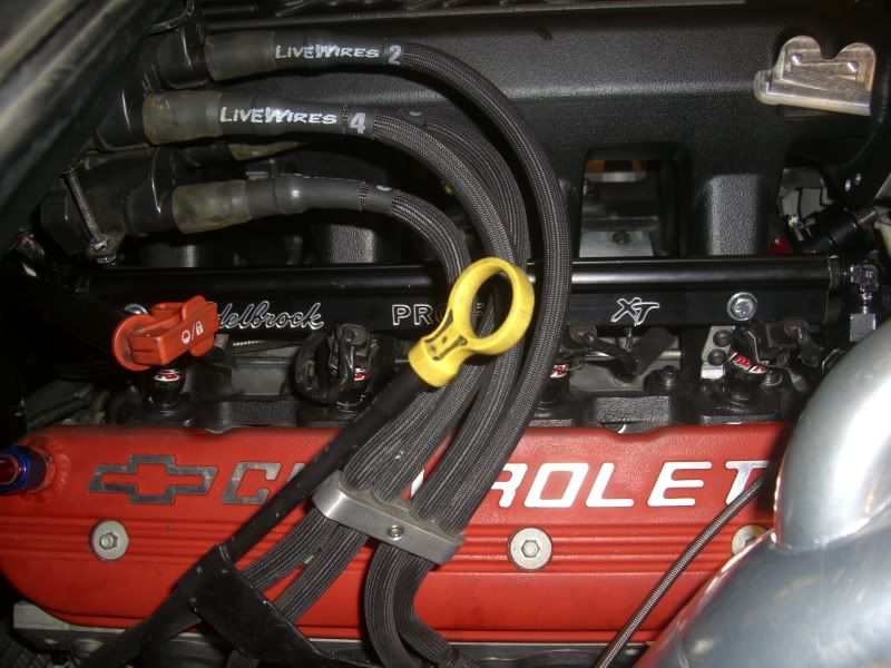
Before I can clip everything in I have to figure out a way to keep the main harness off the header, anyone have any suggestions?
Here it where I want it to be...
And here's how it currently lies, it pretty much just sits on the manifold. Things gonna cook obviously so...anyone...anyone...?
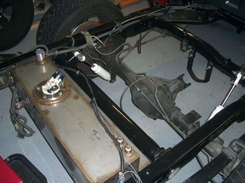
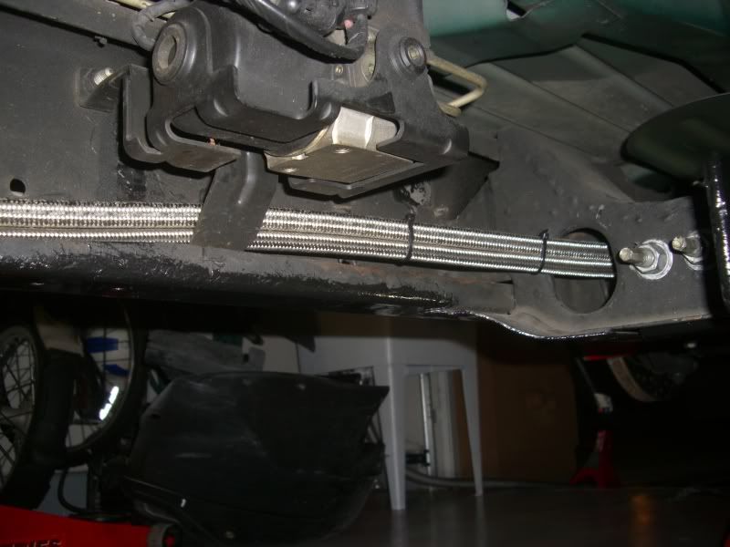
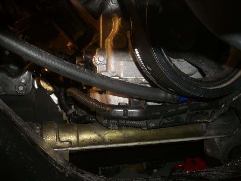
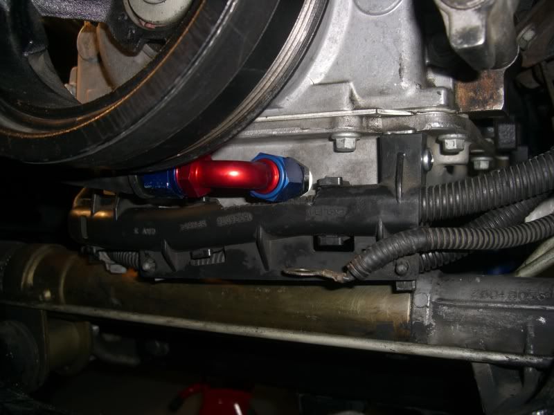
I also got around to running the turbo oil supply and return, here's where I ended up placing the return...
First, here's the carnage from yesterday...
This is the last cross member under the bed closest to the bumper, looks like my payload capabilities have been affected!!
I needed to cut it out so the filler and fuel bucket would clear, I've since cleaned up the cuts so they are smooth as a elephants ***...And I cut this little section out so that my two extra bungs would have room as well once I decide what I'm gonna do with those eventually...
Here's part of a pile of all the heat shields and crossmembers that I cut-out. I had to drill the bolts out that holds the heat shields in place. This stupid job took me about 3-4 hours.
I also did some zip-tying of the harness up on the firewall so it's not out and all over the place...
When I was fugging around with the wiring I found that my TB connector had a wire pop out
I'm gonna have to fix that...I dropped on my intake for the last time and Torqued it down. Ran the harness on the passenger side so it's all tucked away and mostly out of sight, so this side is pretty much finished...
Here's the diver's side as of now...
Before I can clip everything in I have to figure out a way to keep the main harness off the header, anyone have any suggestions?
Here it where I want it to be...
And here's how it currently lies, it pretty much just sits on the manifold. Things gonna cook obviously so...anyone...anyone...?
I also got around to running the turbo oil supply and return, here's where I ended up placing the return...
Thread Starter
TECH Senior Member
iTrader: (8)
Joined: Jan 2007
Posts: 13,845
Likes: 0
From: Here and sometimes there too.
I finished up all the fuel lines as well, ran them back to the fuel tank and needed to do some wiring before popping the bed on so I got to work on that. Here are a couple grounds (for what I don't know but I assume it's the tail-lights since it part of that harness)...
Drilled a hole in a cross member...
Chipped some paint away so there would be some good contact patch and then popped in a nutzert...
And threw on a bolt. So that's grounded well hopefully...
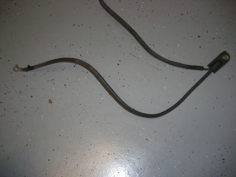
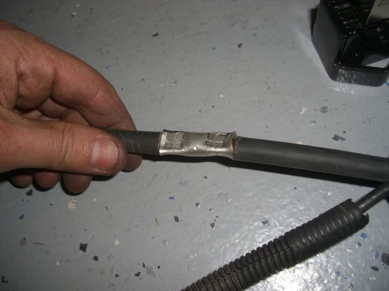
Next I moved on to the battery ground, the stock ground wire is 34" inches in length and I only needed 13" so...
Stock length...
Cut down to 13" inches...
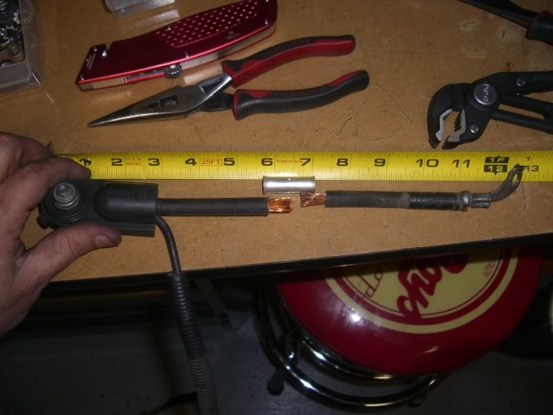
This is a nifty big gauge wire crimper that I got at a welding store. I couldn't afford the $150 crimpers for huge gauge wire but this little $15 gem is awesome!
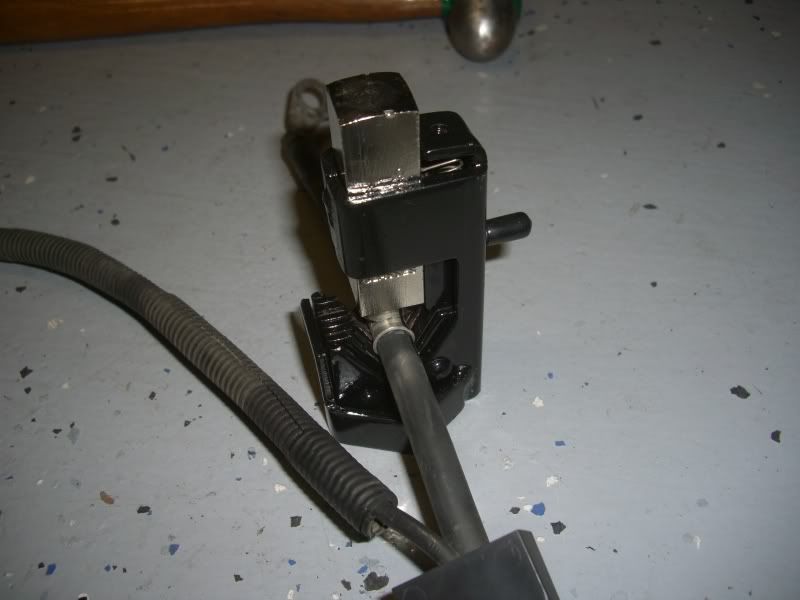
Couple hammer blows later and I have one wire again...
Took a drill to a cross-member again...
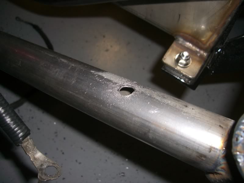
Put in another nutzert or whatever they are called...
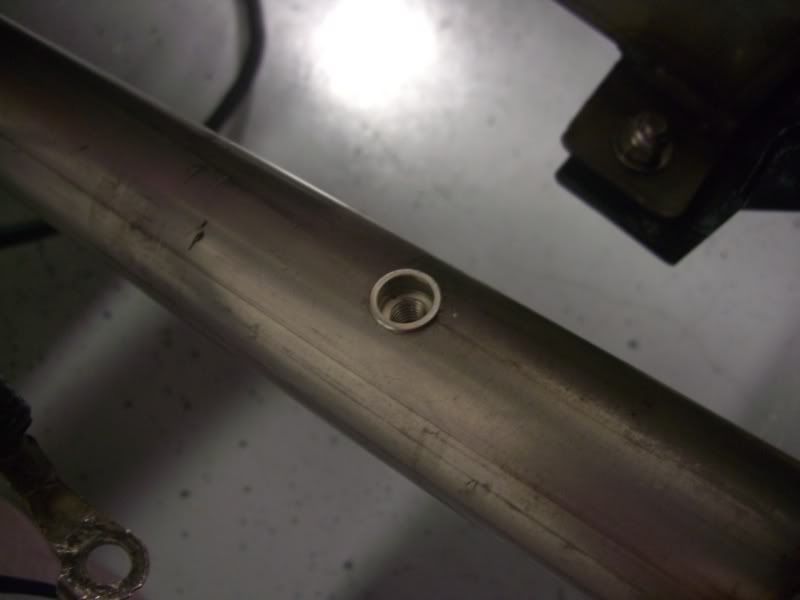
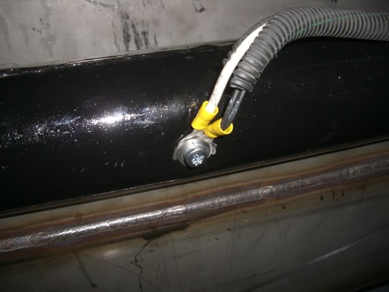
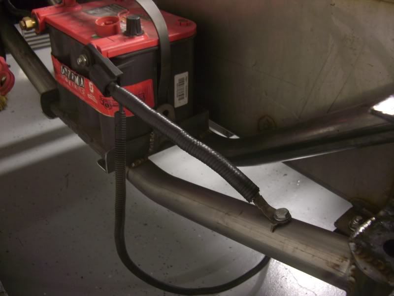
And now I have a shortened battery ground that looks pretty clean...
Drilled a hole in a cross member...
Chipped some paint away so there would be some good contact patch and then popped in a nutzert...
And threw on a bolt. So that's grounded well hopefully...
Next I moved on to the battery ground, the stock ground wire is 34" inches in length and I only needed 13" so...
Stock length...
Cut down to 13" inches...
This is a nifty big gauge wire crimper that I got at a welding store. I couldn't afford the $150 crimpers for huge gauge wire but this little $15 gem is awesome!
Couple hammer blows later and I have one wire again...
Took a drill to a cross-member again...
Put in another nutzert or whatever they are called...
And now I have a shortened battery ground that looks pretty clean...
Thread Starter
TECH Senior Member
iTrader: (8)
Joined: Jan 2007
Posts: 13,845
Likes: 0
From: Here and sometimes there too.
Tomorrow I need to put the bed back on and hopefully I can tow this truck to the exhaust shop where they can take their sweat *** time making it look good and sound better! I just hope the hole that I drilled in the bed for the filler neck is properly aligned...
Guess I'll find out tomorrow!!
Guess I'll find out tomorrow!!
TECH Fanatic
Joined: Aug 2005
Posts: 1,004
Likes: 0
Holy honkin! I seem to have missed some of the latest here. Its lookin great. I had the same idea with the coils for my car. Where did you get that nutzert tool? I used to use one when i worked for the ford plant building those trucks. Off the top of my head for that main harness i would make a bracket a tubular bracket that runs parallel with the master cylinder. secure it using the nut that holds the master on. Weld a small plate to the tube and secure your harness to the plate. If you wanna get a little more creative you can make that plate the contour of the harness to act as a bit of a heat shield for the harness. Just an idea but at least it would secure it away from the header. Thats an idea just off the top of my head. Man its looking good. Did you make those spark plug wires?


Thread Starter
TECH Senior Member
iTrader: (8)
Joined: Jan 2007
Posts: 13,845
Likes: 0
From: Here and sometimes there too.
Sorry I haven't updated this in a while. I shipped out and am now floating around Japan trying to see if I turn a shade of "glow in the dark green". I should be home at the end of May, at which point I have 4 days to finish the truck and compete in Truckin' Magazine's annual Horsepower shootout. Can't wait!!
Here's a small update, got the exhaust finsihed. It's a 4" DP split into two 3" pipes that exit out each bedside. All hot parts are currently being ceramic Coated black, tips included. Cold side I/C piping had to be repaired due to a previous accident.
Enjoy...
http://i2.photobucket.com/albums/y50...Picture006.jpg
http://i2.photobucket.com/albums/y50...Picture013.jpg
http://i2.photobucket.com/albums/y50...Picture012.jpg
http://i2.photobucket.com/albums/y50...Picture018.jpg
http://i2.photobucket.com/albums/y50...Picture014.jpg
http://i2.photobucket.com/albums/y50...Picture011.jpg