
G8 Twin Turbo Build - My Own 'KIT'
 06-07-2011, 12:25 PM
#1
Teching In
Thread Starter
iTrader: (2)

Join Date: Oct 2009
Location: St. Louis
Posts: 12
Likes: 0
Received 0 Likes
on
0 Posts
I figured I've put together enough parts to get things rolling in a thread - I'm pretty close to having everything I need to move forward. Lots of pics to be added, this is just a start.
I'm building my own twin turbo setup, using a variety of parts. I'm a broke father of 3, so I wanted to see how far I could get on my own. Decided to piece everything together over the past 6 months or so, instead of buying a pre-made kit (which there are none left to my knowledge). I figure I'm saving myself about $3k.
Here's a short list of what's going into the build:
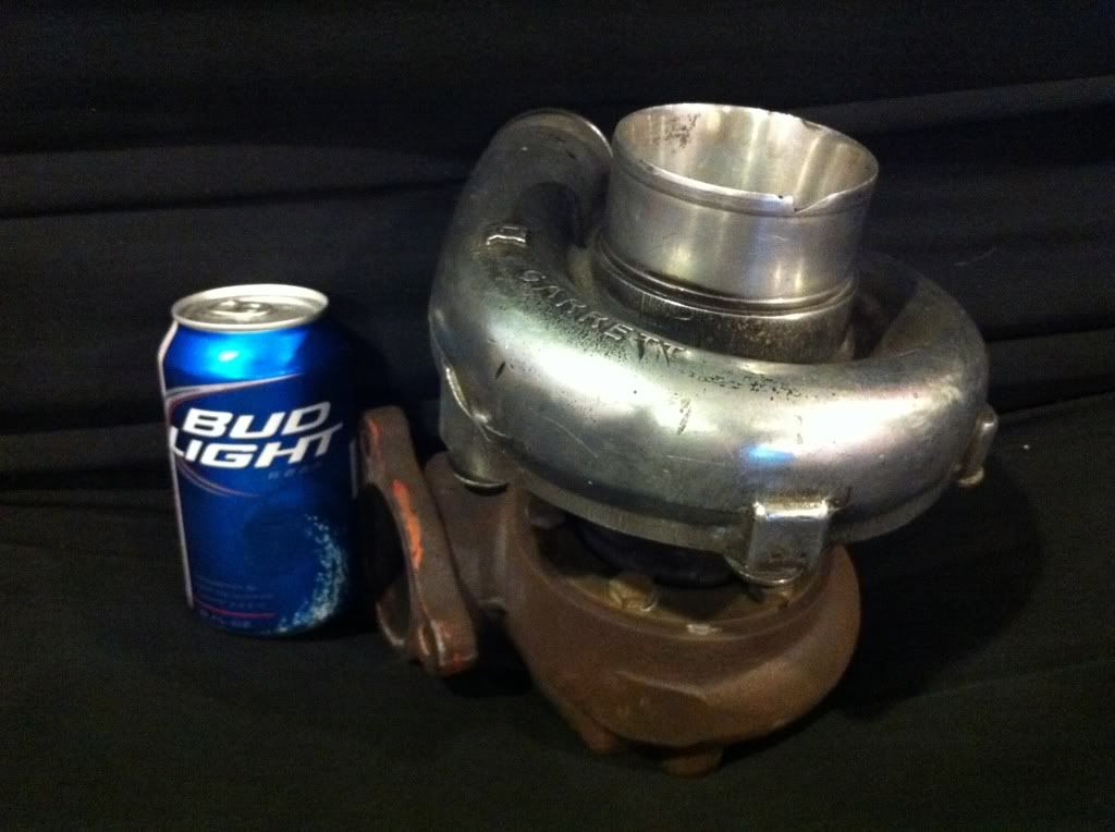
Pics of turbos and housings:
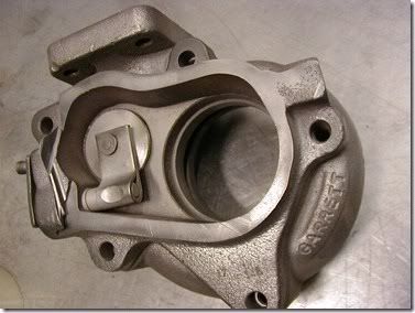
Before housing was replaced (actually going out in the mail tomorrow to get new housings, etc):
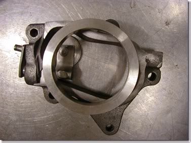
Housing with modified Garrett internal wastegate housing:
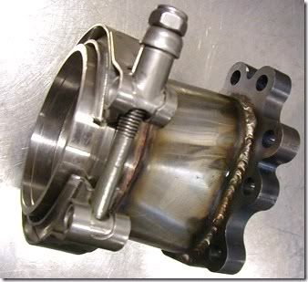
3" vband setup:
What the modified wastegate housings will end up looking close to:
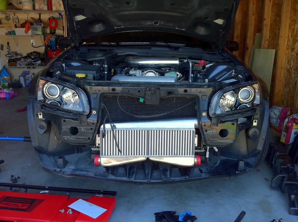
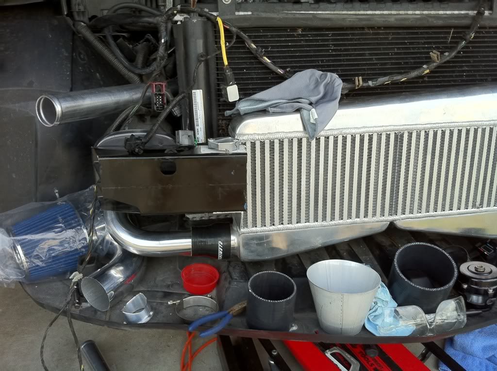
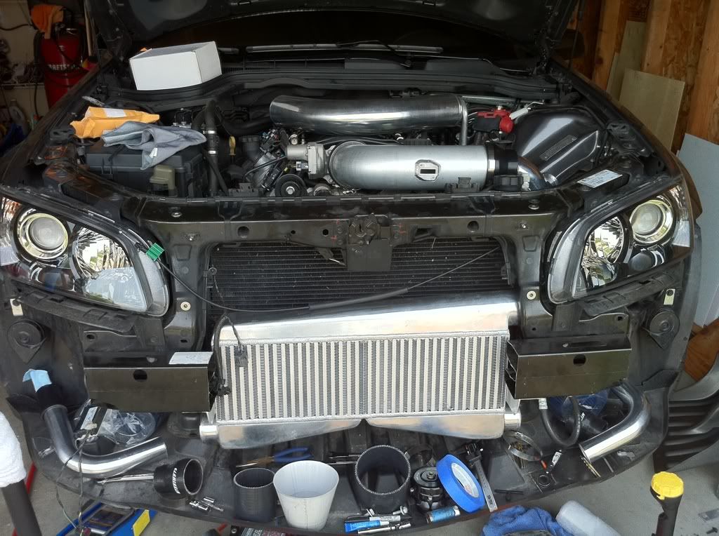
Ripped off the front end of the car, mocking up parts. Intercooler will sit behind the front bumper support slightly. I'll leave clearance for airflow between the i/c and bumper support:
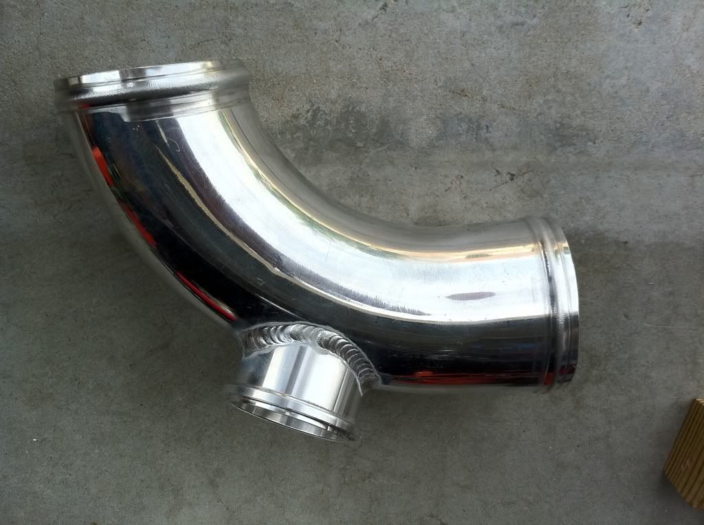
Pic of the 4" intake tubing. It'll be one piece from the throttle body util it makes the turn along the frame rail towards the front of the car. I have conical aluminum to smoothly adapt, instead of using silicone couplers to change the size:
I've been wanting to be done with this by now, but my basement has been taking precidence. Hoping to get more done this week, especially get the intercooler mount brackets setup, then take it to someone to do the welding of the intake parts. My LS7 MAF card and bung should be here shortly. Once I have that, I'll cut and mock everything up, mark where everything lines up, tape it up, and get it welded. Will also have the TiAL BOV flange welded at the same time.
Advice, comments, and pointers are definitely welcome!
I'm building my own twin turbo setup, using a variety of parts. I'm a broke father of 3, so I wanted to see how far I could get on my own. Decided to piece everything together over the past 6 months or so, instead of buying a pre-made kit (which there are none left to my knowledge). I figure I'm saving myself about $3k.
Here's a short list of what's going into the build:
- (2) Precision/Garrett T04E 60 trim, 58mm turbos (TE44's from Buick Grand Nationals). 3" inlet, 2" outlet on the cold side. Hot side: Stage III turbine wheels in Garrett modified 3" v-band .82 A/R housings, internally gated. Completely rebuilt with all Garrett components, new wheels, bearings, etc. Originally going to use some .63 A/R Grand National exhaust housings, but the fab work and space requirements would have me limited. Ditching the external gates.
- ZR1 Injectors (should easily support my starting goals of 500-550whp)
- LS7 MAF card and bung, to be installed in custom 4" intake tubing. Will be using 6:1 ratio honeycomb to straighten the airflow to it, which will ease tuning and MAF voltage fluctuations
- LS9 MAP sensor, to properly tune with boost.
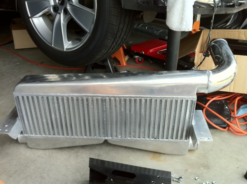
- Dual inlet bar/plate intercooler. 2-1/2" inlets, 3" outlet
- TiAL Q 50mm BOV
- 2" to 2-1/2" all aluminum cold piping to intercooler
- 3" stainless exhaust piping off turbos, throttling down to 2-1/2" before the X-pipe
- 2-1/2" 321 Stainless from manifolds to T3 inlet. Hoping to keep the route short, and minimize the welds.
- 3.6 GPH 12V gear pump to scavenge hot oil from turbos, and return back to oil cap. Using 1/2" push-loc lines into a small reservoir. Aeromotive-style in-line oil filter after the reservoir, before the pump. 1psi check valve after pump to limit oil backing up when car is off
- Autometer fuel pressure and boost gauge. LC-1 w/ HPTuners on laptop to monitor everything else during initial tuning
Pics of turbos and housings:
Before housing was replaced (actually going out in the mail tomorrow to get new housings, etc):
Housing with modified Garrett internal wastegate housing:
3" vband setup:
What the modified wastegate housings will end up looking close to:
Ripped off the front end of the car, mocking up parts. Intercooler will sit behind the front bumper support slightly. I'll leave clearance for airflow between the i/c and bumper support:
Pic of the 4" intake tubing. It'll be one piece from the throttle body util it makes the turn along the frame rail towards the front of the car. I have conical aluminum to smoothly adapt, instead of using silicone couplers to change the size:
I've been wanting to be done with this by now, but my basement has been taking precidence. Hoping to get more done this week, especially get the intercooler mount brackets setup, then take it to someone to do the welding of the intake parts. My LS7 MAF card and bung should be here shortly. Once I have that, I'll cut and mock everything up, mark where everything lines up, tape it up, and get it welded. Will also have the TiAL BOV flange welded at the same time.
Advice, comments, and pointers are definitely welcome!


 06-08-2011, 07:20 AM
#5
Teching In
Thread Starter
iTrader: (2)
Join Date: Oct 2009
Location: St. Louis
Posts: 12
Likes: 0
Received 0 Likes
on
0 Posts
Fabrication cost/complexity. Mostly complexity. I'm doing all the mock-ups on my own, and want to K.I.S.S.
Few reasons:
There's great starter MAF tables for the LS7 MAF in a 4" tube.
4" charge pipe matches up perfectly to the throttle body inlet
I found that 4" 90deg bend for a good price and it had the tight bend I needed to get it to fit.
There's great starter MAF tables for the LS7 MAF in a 4" tube.
4" charge pipe matches up perfectly to the throttle body inlet
I found that 4" 90deg bend for a good price and it had the tight bend I needed to get it to fit.
Trending Topics
 06-09-2011, 01:34 PM
#13
On The Tree
Join Date: Sep 2008
Location: WHERE UNCLE SAM SAYS
Posts: 159
Likes: 0
Received 0 Likes
on
0 Posts
It’s probably too late seeing as you already purchased your FMIC, but are you opposed to running a OTR charge pipe and using a tread stone IC with dual inlets dumping to a single outlet. IMHO if you can do it, it’s worthwhile to facilitate quicker spool and efficiency and eliminate lots of bends. (K.I.S.S.) Primarily the one 90* right after the throttle body.
 06-10-2011, 07:53 AM
#15
Teching In
Thread Starter
iTrader: (2)
Join Date: Oct 2009
Location: St. Louis
Posts: 12
Likes: 0
Received 0 Likes
on
0 Posts
It�s probably too late seeing as you already purchased your FMIC, but are you opposed to running a OTR charge pipe and using a tread stone IC with dual inlets dumping to a single outlet. IMHO if you can do it, it�s worthwhile to facilitate quicker spool and efficiency and eliminate lots of bends. (K.I.S.S.) Primarily the one 90* right after the throttle body.
Or stupid, as my wife likes to think. lol
Got the gear pump in the mail finally:
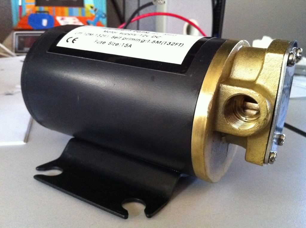
Thinking of where to mount it - most likely in the spot where the APS kit mounts their windshield washer tank (just above the filter in this pic):

It'll have the check valve after it, and a pre-filter before it. I'll have to grab a good shot of the pre-filter I picked up. Should work out just fine.
07-06-2011, 09:53 AM
#17
Teching In
Thread Starter
iTrader: (2)
Join Date: Oct 2009
Location: St. Louis
Posts: 12
Likes: 0
Received 0 Likes
on
0 Posts
So, seriously thinking about doing 3" from the intercooler to the throttle body, to keep charge velocity up, and lag down.
Will the LS7 MAF card run out of range in a 3" tube? I'm guessing I'll max out at ~60lb/min of airflow in my setup (8-10psi)...
Will the LS7 MAF card run out of range in a 3" tube? I'm guessing I'll max out at ~60lb/min of airflow in my setup (8-10psi)...
07-16-2011, 11:34 AM
#18
Teching In
Thread Starter
iTrader: (2)
Join Date: Oct 2009
Location: St. Louis
Posts: 12
Likes: 0
Received 0 Likes
on
0 Posts
Got a LOT done this week. If I can get a few minutes today to extend my MAF wires, I should be able to get it tuned on the new MAF/MAP/injectors. Turbos are ready, but need a day to get it lined up and then have the stainless welded.
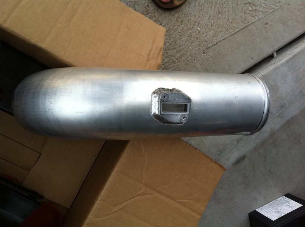
Marked for the new MAF card. Wanted to put it on the back side, but space was limited:
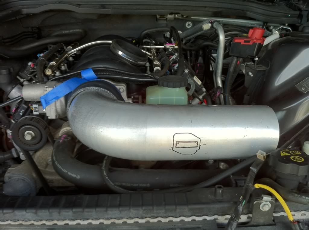
Removed the stock coolant overflow tank to make room for where the piping will go:
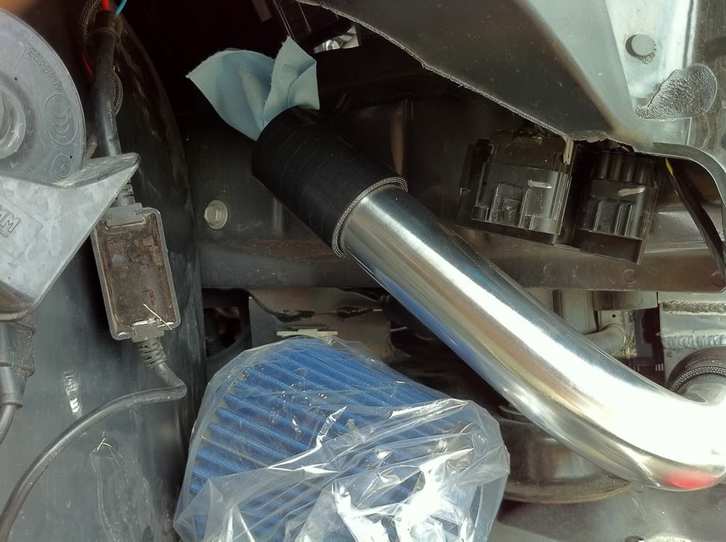
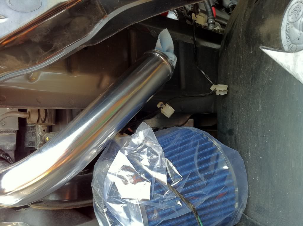
Disregard the pipe sticking out. Was testing to see if I could route through the engine bay instead of the wheel well:
Was able to find someone to weld all my stuff up on short notice. Matt at HTP (now Inertia FabWorks), squeezed me in and did a HELLUVA job! He even bead rolled the piping for me.
Had the brackets welded to the i/c to prevent screws backing out:
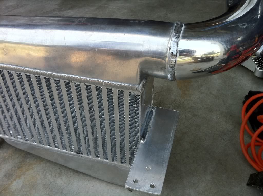
Sweet:
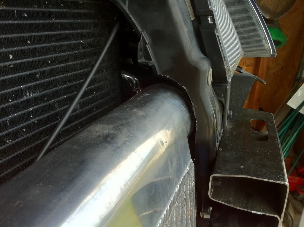
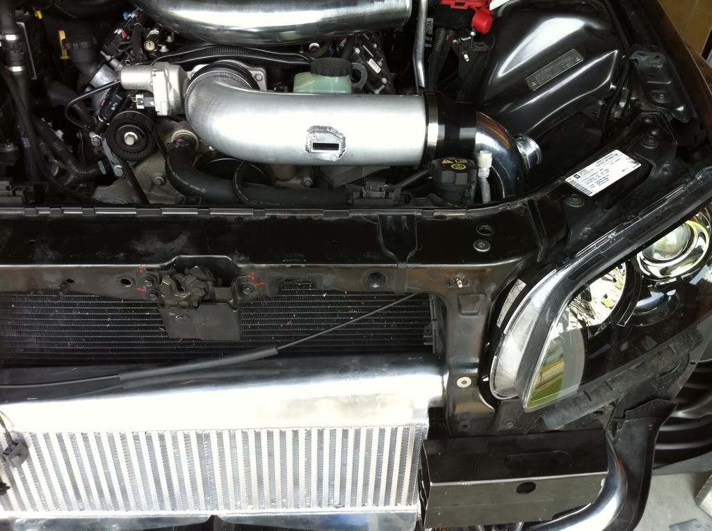
In order to get the intercooler to fit correctly, had to notch and clearance the back of the headlight/radiator frame:
Clearanced:
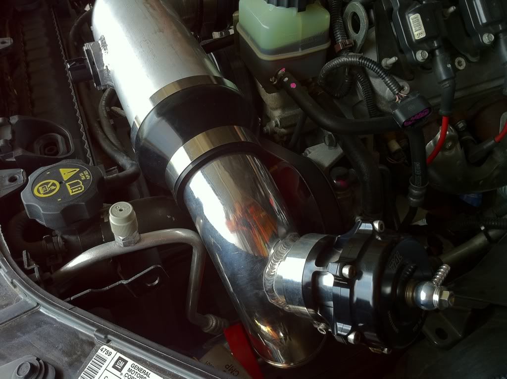
TiAL BOV adapter:
Routing of the driver's side piping:
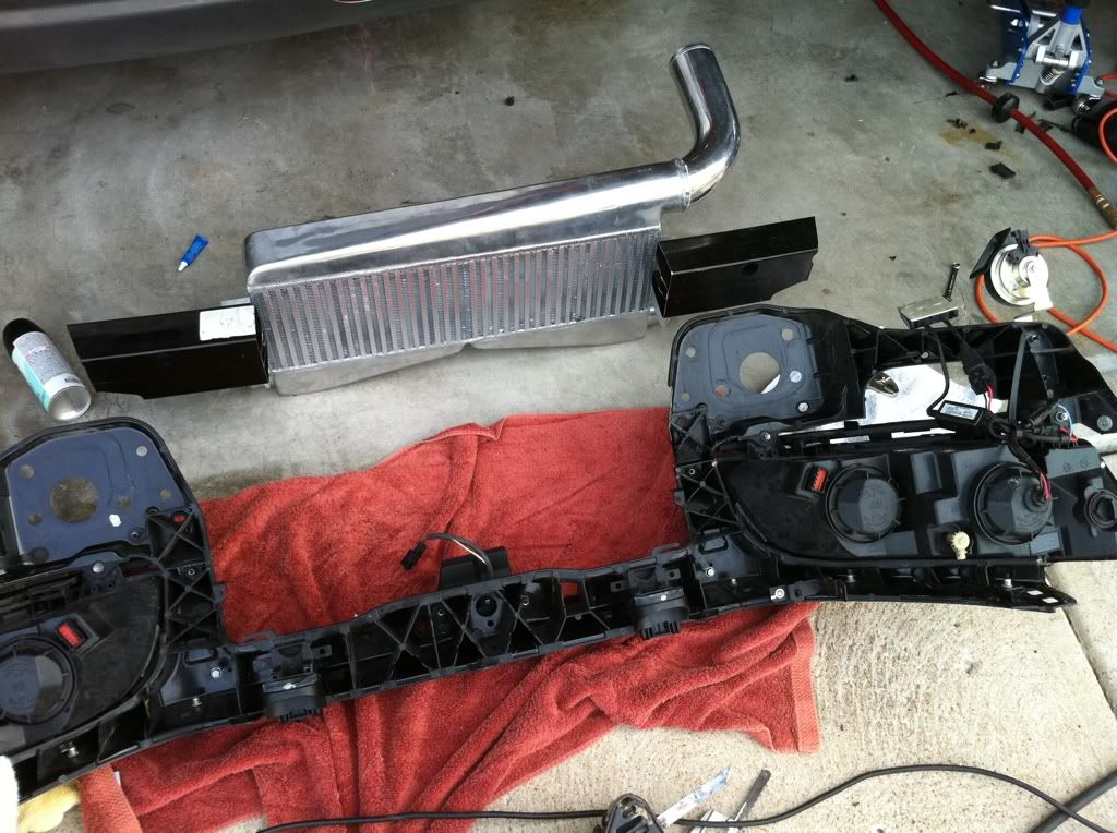
Almost there on the front end. Nice to finally get the headlight assembly off the damn floor:
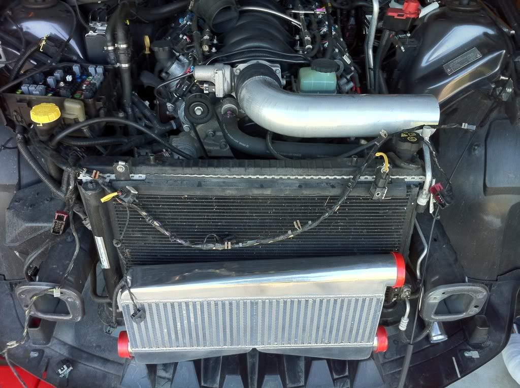
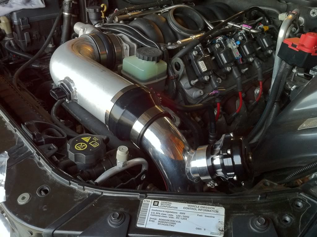
Some nearly finished engine bay shots:
Once it get it running, and get the trims decent enough to drive, I'll put it back up on a lift, and start mocking up the turbo locations. I can't wait.
Side note: Probably going to polish out that 4" tube before the throttle body. I think the polished look would be better than powdercoating it all to match the body color...
Marked for the new MAF card. Wanted to put it on the back side, but space was limited:
Removed the stock coolant overflow tank to make room for where the piping will go:
Disregard the pipe sticking out. Was testing to see if I could route through the engine bay instead of the wheel well:
Was able to find someone to weld all my stuff up on short notice. Matt at HTP (now Inertia FabWorks), squeezed me in and did a HELLUVA job! He even bead rolled the piping for me.
Had the brackets welded to the i/c to prevent screws backing out:
Sweet:
In order to get the intercooler to fit correctly, had to notch and clearance the back of the headlight/radiator frame:
Clearanced:
TiAL BOV adapter:
Routing of the driver's side piping:
Almost there on the front end. Nice to finally get the headlight assembly off the damn floor:
Some nearly finished engine bay shots:
Once it get it running, and get the trims decent enough to drive, I'll put it back up on a lift, and start mocking up the turbo locations. I can't wait.
Side note: Probably going to polish out that 4" tube before the throttle body. I think the polished look would be better than powdercoating it all to match the body color...