


Project Thunderturd - A Sloppy Inspired Creation

Thread Starter
TECH Apprentice
iTrader: (2)
Joined: Nov 2011
Posts: 319
Likes: 0
From: Newport News, VA
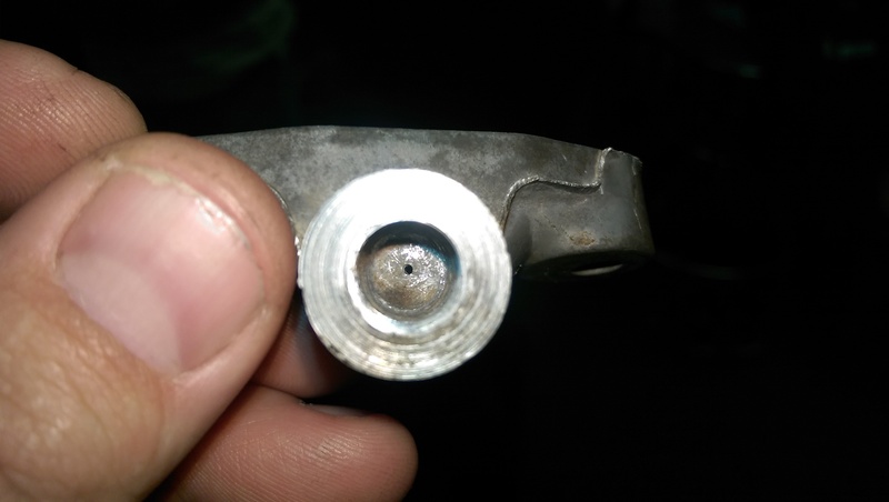
So I couldn't find an adapter that had a restrictor for the turbo oil feed that fit the oil pan. The stuff I had ordered was too short, so I decided to make my own from the factory bypass. I just drilled a 0.035" hole in the bypass and made some 1/8" NPT threads in the factory piece.
Also, the fuel injector fairy came to visit. Siemens Deka 80 lb.

Also, the fuel injector fairy came to visit. Siemens Deka 80 lb.

YOu will be totally find with the dp and turbo being close to the radiator and rack. My turbo is like 1/8 max from radiator fans, same with my hot side to rack boot. Been running fine for 20k miles with a turbo blanket and the regular heat wrap on the hot side.
Thread Starter
TECH Apprentice
iTrader: (2)
Joined: Nov 2011
Posts: 319
Likes: 0
From: Newport News, VA
3 day weekend coming up so there should be a hotside nearly done I hope.
When I put the turbo kit on it melted. I compared it to the the other side factory one and it was a lot softer and weaker. Went to the dealer bought a factory one, wrapped the hot side and its been good to go for about 6 years and 20k miles, 150 track passes,1 million highway blasts at 20psi haha.
Alex
[QUOTE=Black89Z51;19109167]So not much to update really. Been working disgusting hours lately at work.
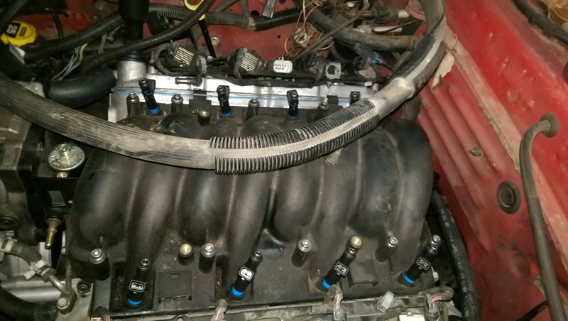
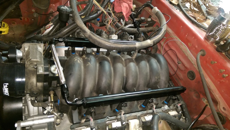
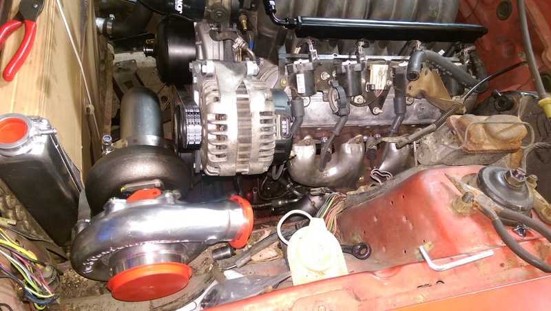
LS1 Intake fits great and it will fit below the hood. I can't believe how much lower this intake sits. Thanks to member EarlyZ28! For the intake!
Awesome man! Glad your happy with the intake.. Awesome to see a lil bit of nightmaro in someone else's car!
LS1 Intake fits great and it will fit below the hood. I can't believe how much lower this intake sits. Thanks to member EarlyZ28! For the intake!
Awesome man! Glad your happy with the intake.. Awesome to see a lil bit of nightmaro in someone else's car!
Thread Starter
TECH Apprentice
iTrader: (2)
Joined: Nov 2011
Posts: 319
Likes: 0
From: Newport News, VA
Thanks man! You've inspired most of this, and your posts here and your wiki are really what allows most of this to happen. This should be a busy weekend. I'm hoping to get the trans in and the hotside mostly complete.
[QUOTE=EarlyZ28!;19145696] Thanks again! The intake worked out perfect.
[QUOTE=EarlyZ28!;19145696]
So not much to update really. Been working disgusting hours lately at work.
LS1 Intake fits great and it will fit below the hood. I can't believe how much lower this intake sits. Thanks to member EarlyZ28! For the intake!
Awesome man! Glad your happy with the intake.. Awesome to see a lil bit of nightmaro in someone else's car!
LS1 Intake fits great and it will fit below the hood. I can't believe how much lower this intake sits. Thanks to member EarlyZ28! For the intake!
Awesome man! Glad your happy with the intake.. Awesome to see a lil bit of nightmaro in someone else's car!
LS1 Tech Stories
The Best V8 Stories One Small Block at Time

6 Common C5 Corvette Failures and What's Involved In Repairing Them
Pouria Savadkouei
Retro Modern Bandit Pontiac Trans AM Comes With Burt Reynolds' Autograph
Verdad Gallardo
Top 10 Greatest Cadillac V Series Performance Models Ever, Ranked
Pouria Savadkouei
Top 10 Most Powerful Chevy Trucks Ever Made!

Hennessey's New Supercharged Silverado ZR2 Has 700 HP
Verdad Gallardo
Coachbuilt N2A Anteros Is an LS2-Powered C6 Corvette In Italian Clothes
Verdad Gallardo
Awesome K5 Blazer Restomod Comes With C7 Corvette Power
Verdad Gallardo
10 Camaros You Should Never Buy

10 LS Engine Myths That Refuse to Die
Verdad Gallardo Thread Starter
TECH Apprentice
iTrader: (2)
Joined: Nov 2011
Posts: 319
Likes: 0
From: Newport News, VA
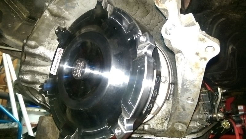
So I managed to start working on the transmission bits. Got the Circle D torque converter installed. Went in without a hitch. The only bitch I have about it is that it's too pretty to be put in such an obscure location.
For the crossmemeber, I decided to widen the holes up a bit on the factory piece just to see what it looked like. Believe it or not, it's literally the same height as the factory, just moved back approximately 10-12".
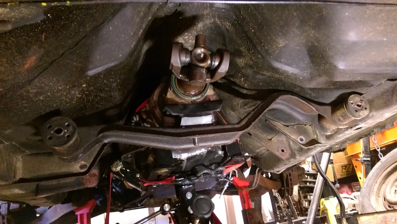
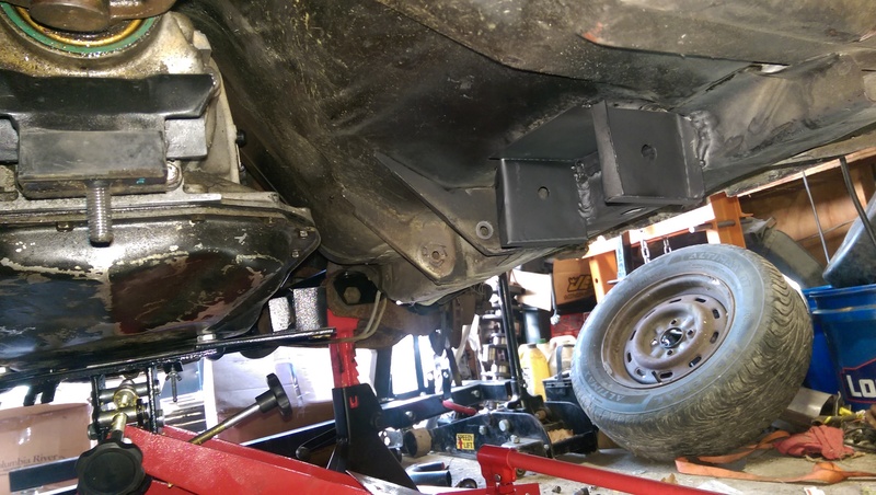
Instead of trying to cut out and re-weld the factory pieces, I decided to make my own using the factory design more or less. I had to modify it a bit to fit the underside, and it still needs some tweaks, but this is what I came up with for the drivers side.
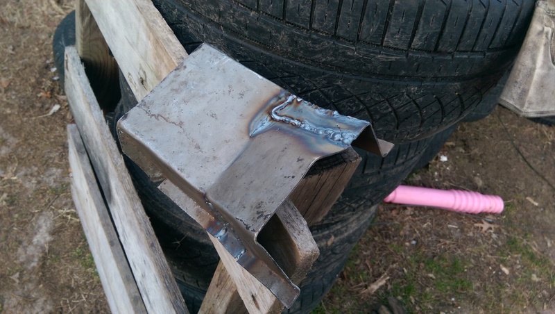
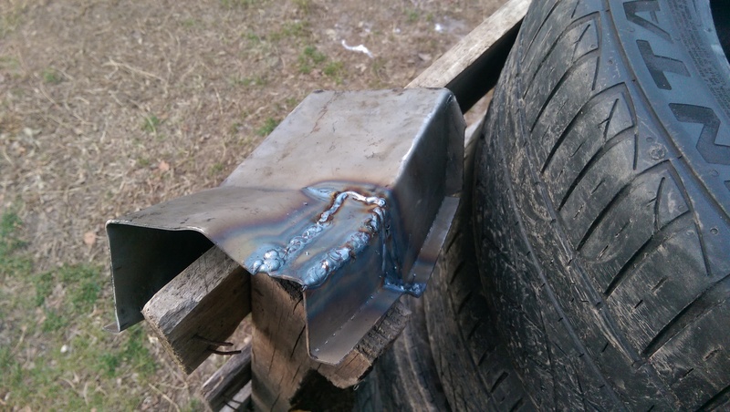
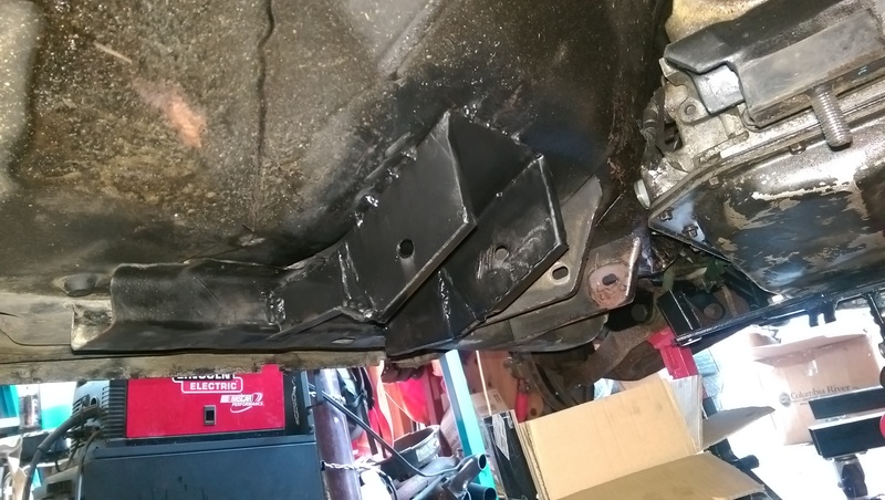
And in it's end location.
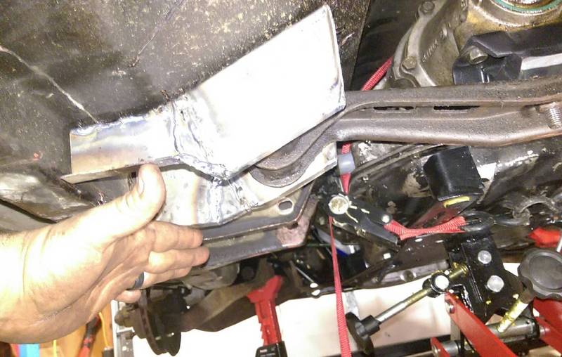
I have fabbed up the passenger side, just haven't taken pictures yet. I've got a sick little person so there won't be much work done today, but I should have the mounts welded in place and the trans jack removed by the end of the week. Then time to start the hot side.

For the crossmemeber, I decided to widen the holes up a bit on the factory piece just to see what it looked like. Believe it or not, it's literally the same height as the factory, just moved back approximately 10-12".

Instead of trying to cut out and re-weld the factory pieces, I decided to make my own using the factory design more or less. I had to modify it a bit to fit the underside, and it still needs some tweaks, but this is what I came up with for the drivers side.


And in it's end location.

I have fabbed up the passenger side, just haven't taken pictures yet. I've got a sick little person so there won't be much work done today, but I should have the mounts welded in place and the trans jack removed by the end of the week. Then time to start the hot side.
Thread Starter
TECH Apprentice
iTrader: (2)
Joined: Nov 2011
Posts: 319
Likes: 0
From: Newport News, VA
Decent amount of progress lately. Transmission x member is finally in and done.
eBay fuel rails are installed.
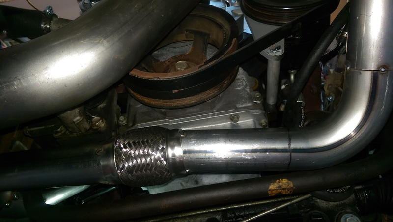
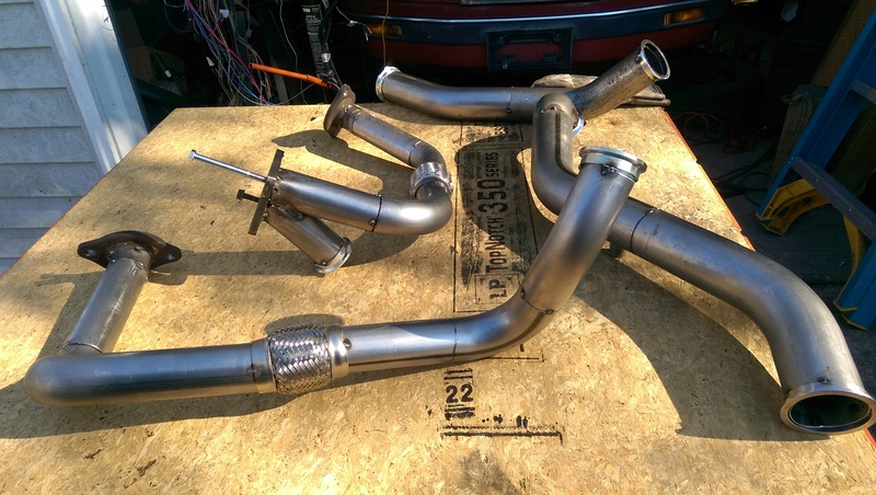
Here is the merge to the turbo. I'm using 2.25" pipe for the up pipes.
Driver's side pipe to the merge.
From the manifold.
Here's the turbo sitting on its flange. I also started making the down pipe.
So far so good. Tomorrow I hope to get the passenger up pipe mostly run. I'm still waiting on some v-bands to come in so that I can remove that side if needed relatively easily. They should be in on monday though.


eBay fuel rails are installed.

Here is the merge to the turbo. I'm using 2.25" pipe for the up pipes.

Driver's side pipe to the merge.

From the manifold.


Here's the turbo sitting on its flange. I also started making the down pipe.

So far so good. Tomorrow I hope to get the passenger up pipe mostly run. I'm still waiting on some v-bands to come in so that I can remove that side if needed relatively easily. They should be in on monday though.
Thread Starter
TECH Apprentice
iTrader: (2)
Joined: Nov 2011
Posts: 319
Likes: 0
From: Newport News, VA
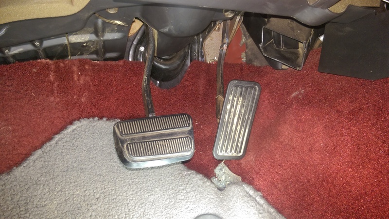
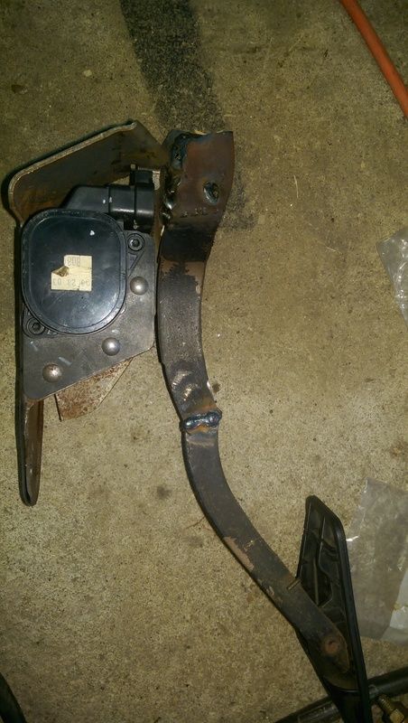
Finally got some time to work on the car today. Focused on getting the accelerator pedal where it should be. Took out the old one and test fitted the new one. Since the Tahoe I removed the pedal from had the adjustable pedals, I had to cut and weld the pedal arm because it was massive. Also I had to make a couple bends to clear the trans tunnel so that the pedal didn't get caught on the carpet.
Welded up.

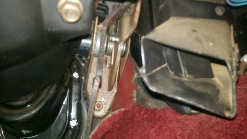
Enlarged the hole for the stud and it bolted right in. Looks almost factory.

Looks pretty good in there.
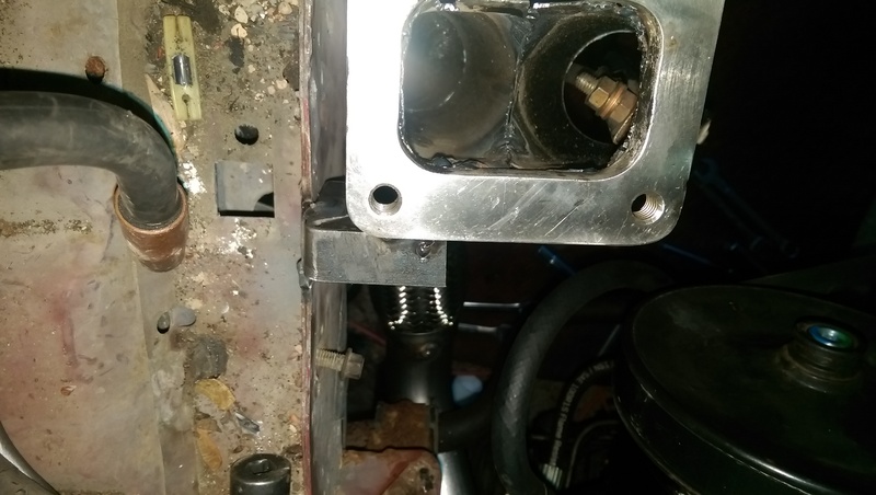
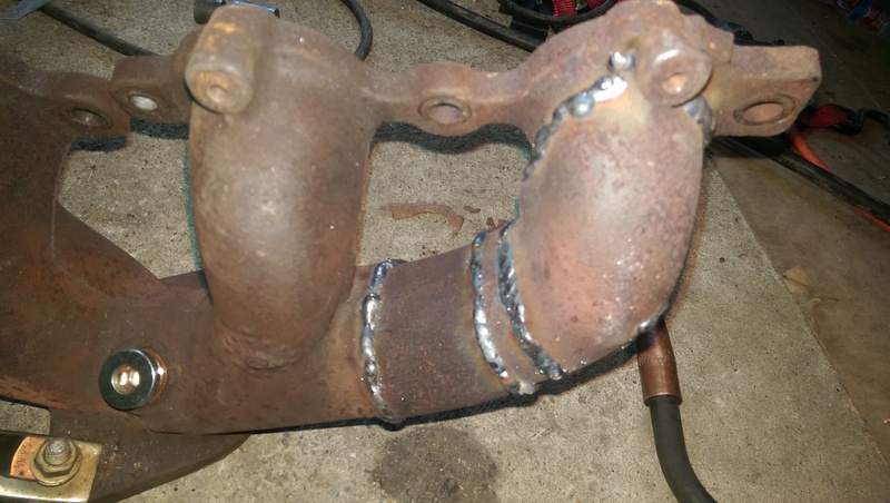
Been tackling the drivers' exhaust manifold where it was hitting the U-joint on the steering shaft and have that figured out I think. Going to work on that some more tomorrow and then (hopefully) start on the passenger up pipe.
Also, a few questions.
My question regards the MAF and the PCM placement. Should I move the PCM to the passenger compartment? The reason I ask is that I have to extend a LOT of wires if so. If that's the best path, I have no problem doing it, but if it's not necessary then I'd like to avoid doing that much work for almost nothing. If I need to extend, is 18 ga TXL wire equivalent to factory? (I'll be soldering and shrink wrapping the wires together if I go this route. Also, if extending, I would just cut the wire in the middle somewhere and just use black so that the appropriate colors are at the PCM and the connector to avoid buying 30 different rolls of wire.)
Regarding the MAF, since this engine (L59) came with both a MAP and a MAF, would it be alright to just remove the MAF pinouts since I will be using MAP for the FI build? Also I will be disabling the O2 sensors and using HP tuners for a VE tune only, so I don't see why I should leave those in the harness either.
Just a few questions, hopefully this clears things up for me. Thanks in advance!
Welded up.

Enlarged the hole for the stud and it bolted right in. Looks almost factory.

Looks pretty good in there.

Been tackling the drivers' exhaust manifold where it was hitting the U-joint on the steering shaft and have that figured out I think. Going to work on that some more tomorrow and then (hopefully) start on the passenger up pipe.
Also, a few questions.
My question regards the MAF and the PCM placement. Should I move the PCM to the passenger compartment? The reason I ask is that I have to extend a LOT of wires if so. If that's the best path, I have no problem doing it, but if it's not necessary then I'd like to avoid doing that much work for almost nothing. If I need to extend, is 18 ga TXL wire equivalent to factory? (I'll be soldering and shrink wrapping the wires together if I go this route. Also, if extending, I would just cut the wire in the middle somewhere and just use black so that the appropriate colors are at the PCM and the connector to avoid buying 30 different rolls of wire.)
Regarding the MAF, since this engine (L59) came with both a MAP and a MAF, would it be alright to just remove the MAF pinouts since I will be using MAP for the FI build? Also I will be disabling the O2 sensors and using HP tuners for a VE tune only, so I don't see why I should leave those in the harness either.
Just a few questions, hopefully this clears things up for me. Thanks in advance!


Finally got some time to work on the car today. Focused on getting the accelerator pedal where it should be. Took out the old one and test fitted the new one. Since the Tahoe I removed the pedal from had the adjustable pedals, I had to cut and weld the pedal arm because it was massive. Also I had to make a couple bends to clear the trans tunnel so that the pedal didn't get caught on the carpet.
Welded up.
Enlarged the hole for the stud and it bolted right in. Looks almost factory.
Looks pretty good in there.

Been tackling the drivers' exhaust manifold where it was hitting the U-joint on the steering shaft and have that figured out I think. Going to work on that some more tomorrow and then (hopefully) start on the passenger up pipe.
Also, a few questions.
My question regards the MAF and the PCM placement. Should I move the PCM to the passenger compartment? The reason I ask is that I have to extend a LOT of wires if so. If that's the best path, I have no problem doing it, but if it's not necessary then I'd like to avoid doing that much work for almost nothing. If I need to extend, is 18 ga TXL wire equivalent to factory? (I'll be soldering and shrink wrapping the wires together if I go this route. Also, if extending, I would just cut the wire in the middle somewhere and just use black so that the appropriate colors are at the PCM and the connector to avoid buying 30 different rolls of wire.)
Regarding the MAF, since this engine (L59) came with both a MAP and a MAF, would it be alright to just remove the MAF pinouts since I will be using MAP for the FI build? Also I will be disabling the O2 sensors and using HP tuners for a VE tune only, so I don't see why I should leave those in the harness either.
Just a few questions, hopefully this clears things up for me. Thanks in advance!
Welded up.
Enlarged the hole for the stud and it bolted right in. Looks almost factory.
Looks pretty good in there.
Been tackling the drivers' exhaust manifold where it was hitting the U-joint on the steering shaft and have that figured out I think. Going to work on that some more tomorrow and then (hopefully) start on the passenger up pipe.
Also, a few questions.
My question regards the MAF and the PCM placement. Should I move the PCM to the passenger compartment? The reason I ask is that I have to extend a LOT of wires if so. If that's the best path, I have no problem doing it, but if it's not necessary then I'd like to avoid doing that much work for almost nothing. If I need to extend, is 18 ga TXL wire equivalent to factory? (I'll be soldering and shrink wrapping the wires together if I go this route. Also, if extending, I would just cut the wire in the middle somewhere and just use black so that the appropriate colors are at the PCM and the connector to avoid buying 30 different rolls of wire.)
Regarding the MAF, since this engine (L59) came with both a MAP and a MAF, would it be alright to just remove the MAF pinouts since I will be using MAP for the FI build? Also I will be disabling the O2 sensors and using HP tuners for a VE tune only, so I don't see why I should leave those in the harness either.
Just a few questions, hopefully this clears things up for me. Thanks in advance!
The PCM in most applications for the LS series esp in trucks has it located in the engine bay (the 5.3 I got had it mounted behind the driver headlight in the engine bay). They are weather resistant for a reason lol. They are fine in the engine bay but I wouldn't mount it right over or next to a header ya know. Most OEM almost now always mount the ECM in the engine bay, including my ram, wife's jeep, brothers Denali, mom and sis Ford Fusion and even a 2003 Saturn ion lol.
I just mounted my 5.3 PCM and finished my harness last night. I mounted the ECM on the pass firewall by the fender. To do this was a PITA as the PCMs are not that small lol in the gen 3 0411's. The newer gen 5 PCMs are more powerful yet smaller. The PITA part was the ECM was mounted originally front pass side, I wanted it on the rear pass side for a cleaner look without the PCM just sticking out in plain site. I had to cut all the wires and shorten them while keeping it all on the right side with the ECM being flipped. Mounting it inside the car like you would require ALOT of extra wire being added and I didn't see the need since it was mounted under the hood originally. I would have not done that with the original TPI ECM which was mounted behind the passenger dash as that thing was not weather resistant. So I would not go through the hassle of relocating it inside unless cosmetically it's what you want.
I'm in the same boat with u on the tuning. Originally a MAF PCM and I'm going SD. I removed the MAF wiring back far enough to coil harness but left it pinned. You never know if you'll need it. But it will be unused. You need to keep 2 of the 5 wires for the IAT sensor, MAFs have them built into the MAF itself hence the 5 wires. You need to isolate the 2. (IAT signal and ground) and order a replacement of your choice with pigtail. I went with FAST bc it was cheap and a PiCo pigtail. Mine is mounted in the EGR block off plate. Your PCM will need a new 2 or 3 bar OP system so you won't be able to run the MAF anyways so get ready to spend the credits. Don't forget to get a matchin MAP sensor for whatever OP system you choose.
I would leave the rear 02s in as they will only help with your part throttle economy and running.
Thread Starter
TECH Apprentice
iTrader: (2)
Joined: Nov 2011
Posts: 319
Likes: 0
From: Newport News, VA
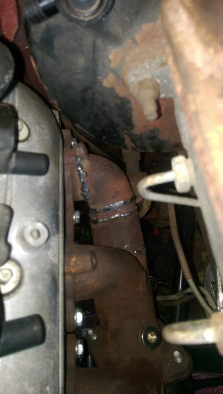
Had a huge day Saturday. Finally fixed the manifold/steering shaft interference problem. I ended up cutting the manifold up and clocking the primary about 5 degrees clockwise, tacked it in place and it didn't hit. i welded it up (inside and outside) and used another section of cast from the passenger manifold that was removed from the donor. Turned out pretty good I think.
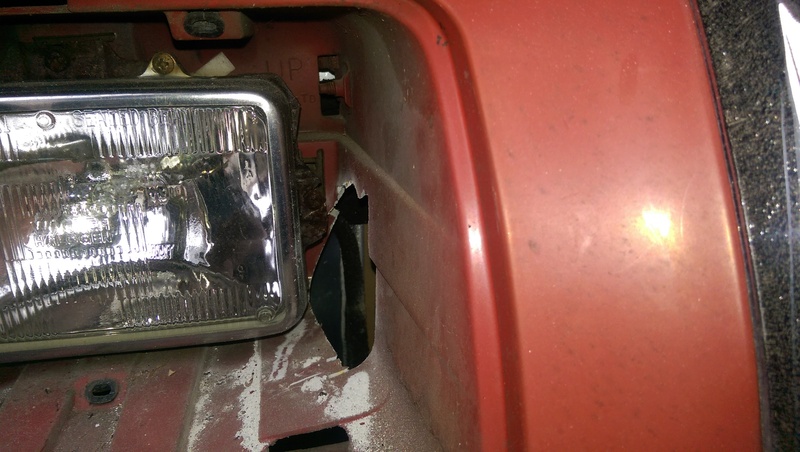
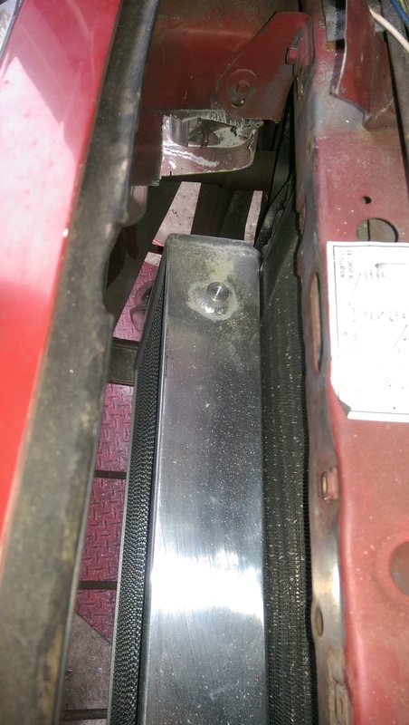
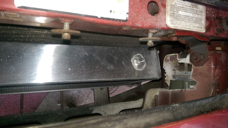
Played around with intercooler placement. Had to hack at the headlight buckets with the sawzall to raise the IC a bit, but it works and I'll be happy with where it can go. All that's left to do is make the mounts.
I have been procrastinating on the down pipe and up pipe from the passenger side because I figured they were going to be a bitch, but it ended up taking a lot less time and fabrication that initially thought. I still need to get the wastegate plumbed, but that should be pretty easy.
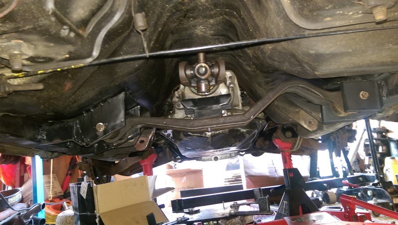
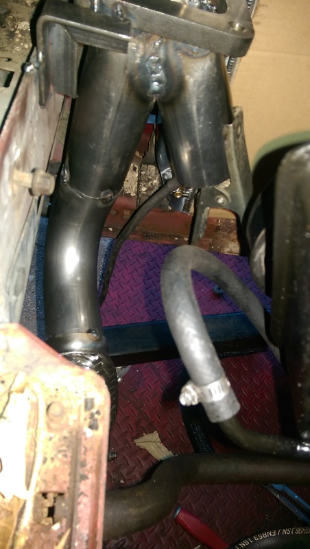
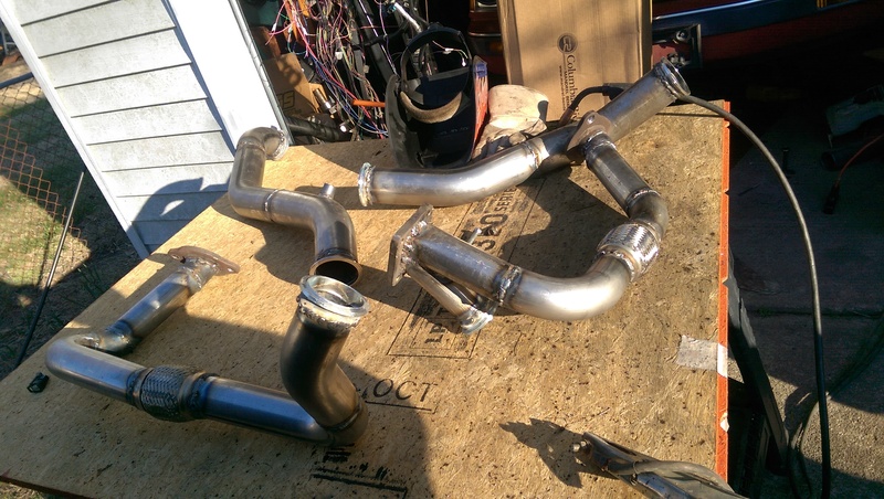
Here's the down pipe from the turbo across.
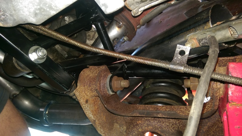
And here's where it gets "complicated". Through the suspension.
You can see where it goes behind the spring, through the K member and where my welder ground is attached is right by the starter. Ended up only using two 45 degree bends. A whole lot simpler than I initially thought. I figured I was going to have to pie cut the **** out of some U bends.
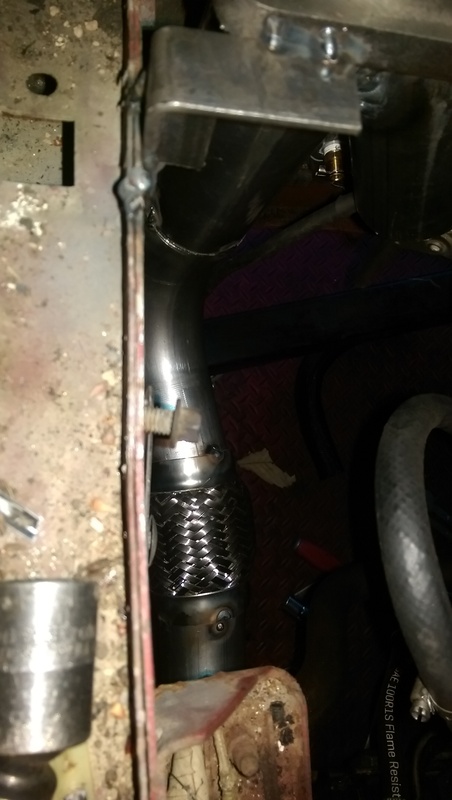
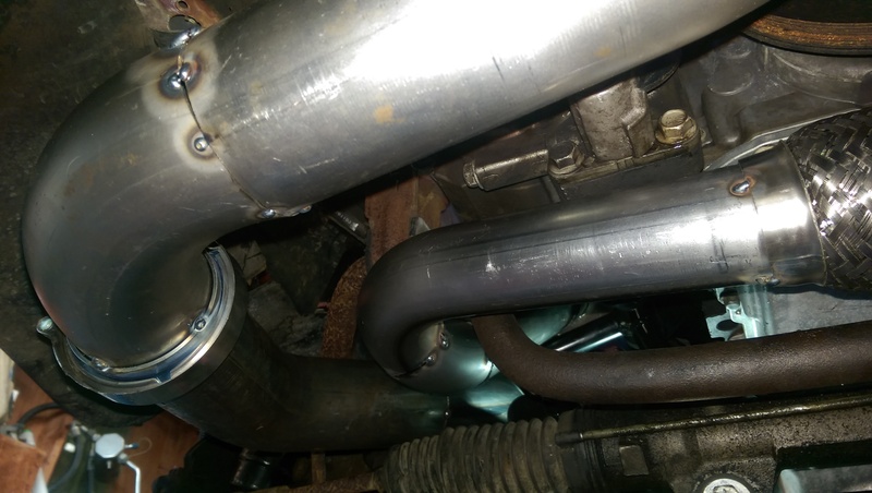
Here's the merge up to the turbo. V band is on the pipe from the passenger side.

Above you can see where it comes down and around the sway bar.
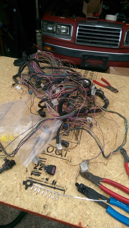
Today I'm going to start tackling the wiring monster. I have already changed over the injector connectors to fit my injectors, which was pretty easy. just need to straighten out and tidy up this mess. I also picked up a Current Performance fuse/relay swap harness. That is definitely going to make things a lot easier.


Played around with intercooler placement. Had to hack at the headlight buckets with the sawzall to raise the IC a bit, but it works and I'll be happy with where it can go. All that's left to do is make the mounts.


I have been procrastinating on the down pipe and up pipe from the passenger side because I figured they were going to be a bitch, but it ended up taking a lot less time and fabrication that initially thought. I still need to get the wastegate plumbed, but that should be pretty easy.
Here's the down pipe from the turbo across.

And here's where it gets "complicated". Through the suspension.

You can see where it goes behind the spring, through the K member and where my welder ground is attached is right by the starter. Ended up only using two 45 degree bends. A whole lot simpler than I initially thought. I figured I was going to have to pie cut the **** out of some U bends.

Here's the merge up to the turbo. V band is on the pipe from the passenger side.


Above you can see where it comes down and around the sway bar.
Today I'm going to start tackling the wiring monster. I have already changed over the injector connectors to fit my injectors, which was pretty easy. just need to straighten out and tidy up this mess. I also picked up a Current Performance fuse/relay swap harness. That is definitely going to make things a lot easier.


Thread Starter
TECH Apprentice
iTrader: (2)
Joined: Nov 2011
Posts: 319
Likes: 0
From: Newport News, VA
Thanks guys! It took a little bit of thought, but eventually I just said "screw it" and cut it. Bolted it back up and clocked it a bit and tried the wheel and it didn't hit so I welded it up and then made the transition pieces.
Thread Starter
TECH Apprentice
iTrader: (2)
Joined: Nov 2011
Posts: 319
Likes: 0
From: Newport News, VA
So work has been pretty slow. Had to go out of town for a funeral so no work done this past weekend. Got back out there today and took the exhaust apart and worked on welding everything up. They certainly don't qualify as weld ****, but they work.
Before
After. Also added the bung for the wideband.
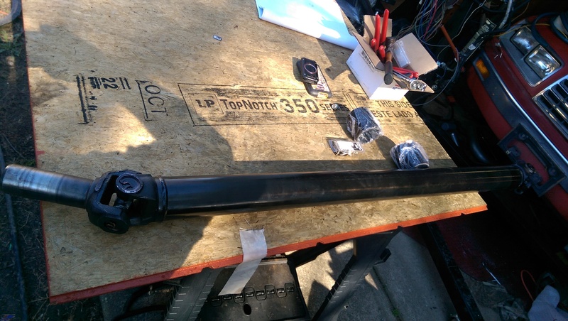
I also had a driveshaft made while I was out of town. 1350 front u-joint and a 1350/1310 rear. I may end up switching the rear flange to use a full 1350 u-joint, but we'll see how this one holds up.
Before

After. Also added the bung for the wideband.

I also had a driveshaft made while I was out of town. 1350 front u-joint and a 1350/1310 rear. I may end up switching the rear flange to use a full 1350 u-joint, but we'll see how this one holds up.


Thread Starter
TECH Apprentice
iTrader: (2)
Joined: Nov 2011
Posts: 319
Likes: 0
From: Newport News, VA
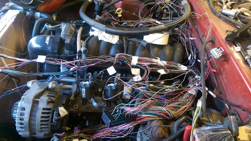
Wiring is the bane of my existence. There are a bunch of wires that I still need to figure out whether they stay or go, but it's getting closer. Instead of shortening a metric **** pile of wires, I'm just going to loop and zip tie them.
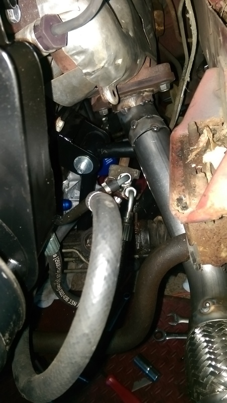
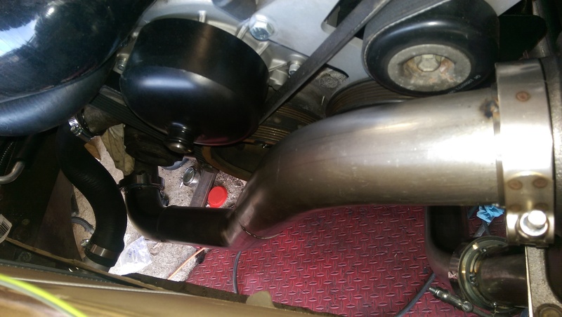
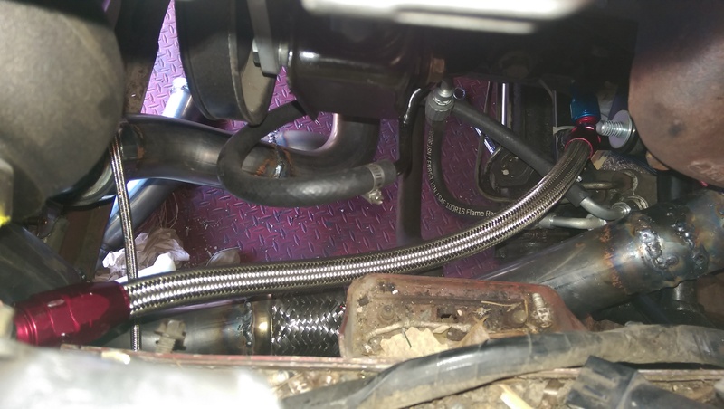
Also got frisky and made the turbo oil return. The only thing left on the hot side is wrapping it and then I can bolt it in for the last time. The picture makes it look close to the up pipe, but it's actually 6-8 inches away.

Also got frisky and made the turbo oil return. The only thing left on the hot side is wrapping it and then I can bolt it in for the last time. The picture makes it look close to the up pipe, but it's actually 6-8 inches away.

