When you click on links to various merchants on this site and make a purchase, this can result in this site earning a commission. Affiliate programs and affiliations include, but are not limited to, the eBay Partner Network.
The CAN connects the Mega the AEM. There are 2 Nanos that are used as frequency translation slaves. My setup needs too many different PWM frequencies than 1 mega can provide, so I use the slaved Nanos to translate the default Mega PWM frequency the special frequency needs of various components. For example, the force motor in the transmission wants 614hz. the lock up solenoid 31hz. The alternator 128 hz and so on.
Looked up the part number and looks like it controls 2 fans.
Connect the 12V power lines and the ignition line. Then a voltmeter between the ground and the control wire. If it reads 12V, then it has an internal 12V pullup and odd are that all you need is a ground sourced pwm signal. If it's 5V, then a 5V pwm should do it. If it's zero, then try a 5V pwm first and then a 12V if it doesn't work. My gut feel says it just needs a ground based one. I use an inexpensive PWM generator to test them.
I did what you said and voltage on the pwm wire pulses from 0v to 5v then 0v to 12v repeatedly. I know this controller has a built in emergency mode so I think it needs the pwm signal at key on to run normal. I did find out it uses a 25hz input and standalone ecu guys say a 5v pwm signal works fine. Less than 5% duty triggers emergency, 15% starts low fan, 95% is full speed.
Has anyone played with the commonly available VW controller 3C0959455F which is also a Gates FCM109? Seems to be used in many VW family models.
I have never seen/played with one in the flesh however they seem to be commonly available and already have pigtails attached so would make it very easy to chop and connect whatever you want in terms of connectors.
At $30-40 new I'm hoping they could be a good option.
It looks like it has a two wire input for pwm, so the first question is whether it will accept the usual GM format PWM which comes out of an e38 pin 58 (at least that is my application anyway).
Second question is power handling capacity. Eyeball test given size/shape/design and the applications it is used in, I would guess it is somewhere in the 200 watt range.
I'm trying to run a Derale fan that sucks 22 amps so I need something more like a 300 watt unit, but to be honest I'm struggling to find an easily sourced unit in this range. Yes, can use the C6/Mercedes/AliExpress clone for 60 bucks and have plenty of power to spare, but the connectors are impossible to find. And as I am in Australia going to wreckers to find a plentiful second hand supply is non-existent.
The only other option I'm looking at which is easily enough available with connectors etc is the Dorman 902-310 however a few times now in this forum it seems 16.6A is the rated capacity so I'm guessing that's somewhere around a 200-250 watt unit which is still a tad short of my target. Has anyone pushed the Dorman to its limits to see if it really can only do 16.6 continuous?
I know there are an endless number of options at hand for pwm radiator fan controllers on Amazon/eBay for $30-50 but the whole "how to get the right connectors" thing is honestly nothing short of a complete pain in the hole. A nice 300 watt controller straight off the shelf with pigtails attached and a $50 price range would be a dream come true. Does this VW/Gates thing potentially solve it?
Yeah, I like the fact that it already has pigtails. I've never seen one yet. I will ask around if any of my friends have one of these. If someone sends one to me, I will test it out and hopefully provide info on how it works (and then return it).
I'm trying to run a Derale fan that sucks 22 amps so I need something more like a 300 watt unit, but to be honest I'm struggling to find an easily sourced unit in this range. Yes, can use the C6/Mercedes/AliExpress clone for 60 bucks and have plenty of power to spare, but the connectors are impossible to find. And as I am in Australia going to wreckers to find a plentiful second hand supply is non-existent.
Do you mean this connector? shhworldsea 1.5mm 9.5mm male female waterproof Oxygen sensor plug 4 position auto housing connector 7283-8497-90
Aliexpress sells them (male and female connectors with terminals) for $12 for 2 sets shipped to Australia.
Do you mean this connector? shhworldsea 1.5mm 9.5mm male female waterproof Oxygen sensor plug 4 position auto housing connector 7283-8497-90
Aliexpress sells them (male and female connectors with terminals) for $12 for 2 sets shipped to Australia.
The 7 way contraption on the bottom of the C6 controller (and its clones) is hard to find. Item 09 4401 94 if I'm right.
If I could find these connectors easy enough new, I'd happily buy the Ali express clone and the connector and give it a go. Alas my best efforts to find it have been fruitless.
Thanks for the tip on these connectors you rederenced. Any hints/tips/tricks on a pwm controller they fit which can handle 300 watts or so? There are many generic ones online, including the Mitsubishi clone which was the start of this thread if I'm right. I don't really like the Mitsubishi clones though, as it seems they are only looking in a 5 volt window and from some of the videos on here it also seems to hitting 100% output on just a 60% or so duty cycle input. So I don't know for sure but I'm guessing they may not be in the 300 watt range and are probably not suitable for what I'm trying to do.
Do you mean this connector? shhworldsea 1.5mm 9.5mm male female waterproof Oxygen sensor plug 4 position auto housing connector 7283-8497-90
Aliexpress sells them (male and female connectors with terminals) for $12 for 2 sets shipped to Australia.
It's the C6 / Mercedes controller plug that I can't seem to find anywhere.
For the connectors you referenced, there seems to be a handful of common designs of pwm controllers available online cheaply enough that use that style of connextor. Here's a few examples below. Does anyone know if any of these generic offerings are handling 300watts and compatible with the GM e38 fan 128Hz pwm output?
I've just realised that I'll also need to replace my fuel pump controller in my Toyota 86 (this is what I have swapped the LS3 into). I'm using a Camaro ZL1 fuel pump which from all indications looks like will suck around 16-17 amps at full tilt.
I'm pretty sure you said earlier in the forum that some of the pwm controllers you've played with over the years may not have the attack/sweep speed/response fast enough on the output as needed for a fuel pump and that they are more suited to cooling fans because who cares if they take a few seconds to respond and slowly come up to speed.
If that's the case, for a fuel pump application, needing 16-17 amps of throughput, would you have any recommendations for which of the controllers you've played with over the years are best suited to this type of application? Note that whilst I am using the GM e38 ecm, I have not yet put a scope on the pwm input to the stock controller so I am not yet 100% sure as to what the frequency or min/Max duty cycle looks like. I would assume whatever the e38 puts out by default. I would also assume that driving the pump with 19/20 kHz would be better for noise control, longevity etc. So a controller that can take a range of pwm frequencies in, but deliver a high frequency out would be preferred.
FYI I've ordered an ebay clone of the late model Crown Vic pwm fan controller. Cheap enough at circa 30 bucks. Thanks to V8 Supra Builder for rebuilding my confidence in being able to buy the connectors.
From what I can see it looks like the Crown Vic fan uses a good 30 amps when direct connected to battery, so fingers crossed the controller will be a good contender to handle a continuous 22 amps for my fan. Let's see how I go with tests once I receive it.
I tried ordering the VW unit but the seller stuffed me around so I gave up. Also after further investigation it looks like the assembly has two built in terminals that socket into the main fan when it is assembled in place. The design is that it is to be mounted in the centre of the fan housing right behind/in front of the motor, with these two terminals going directly into the motor. The pigtails are for the second fan, which in all instances looks to be a smaller diameter fan. This then gets me to thinking that perhaps the capacity of this controller may not be as great as expected on the pigtails to the second fan, and who knows, perhaps even some logic inside for switching either fan on/off at various levels to represent lo, hi, large fan, small fan etc, which would be annoying if we are trying to use it for other purposes across the entire duty cycle. Also not forgetting those two built in terminals, would need to find a connector to suit so it doesn't really solve the whole "off the shelf with pigtails" thing.
I just had to chime in,, you guys in this thread are absolutely amazing! I'm going through an e-fan conversion on my 09 F-150 currently. I ended up doing to Mark8/Grand Marquis dual speed fan with what I think is a rather effective wiring design to power this guy. But you folks went like so over and beyond I mean, this thread was amazing!
I stumbled across this thread because I picked up the C6/Fusion pwm controller at the jy earlier today like.. just because. So I went looking to see if I could incorporate it not expecting to drown is information LOL.
@88matt That Crown vic controller.. is that the one that's mounted to the rear/inside of the fan shroud inline with the power feeds? Model years after 4/2000 I think?
@88matt That Crown vic controller.. is that the one that's mounted to the rear/inside of the fan shroud inline with the power feeds? Model years after 4/2000 I think?
No, that one is different to the one I purchased. I ordered the unit for the later model years 06 - 11 which is a clone of the Dorman 902-209.
It still mounts on the top rear of the fan shroud and connects in line as per your question/idea however it is a slightly different design, layout etc. The concept is still the same though. Also you can buy a complete fan assembly for the Vic which has the fan, integrated shroud and the controller for 200-250 bucks if I'm right (but I only needed the controller so I didn't go digging for that).
One reason I guessed this might be usable is that I saw a yt video of Crown Vic fan troubleshooting showing someone with a scope on the pwm connection and the waveform was showing low duty cycles (e.g. 20%) with small amount of time low, large amount of time high. And the high duty cycles (e.g. 80%) with large amount of time low, small amount of time high. So this conforms to the GM e38 "pull to low" method on the e38 X1 pin 58 pwm fan output which (fingers crossed) should mean it is completely plug and play compatible with my LS3 swap.
Also saw a yt video of someone directly connecting the fan to battery with current meter in place and was sucking 30 amps. This gives me hope this controller was designed for these sorts of levels and should hopefully be strong enough to support my 22 amp fan.
Radiator Cooling Fan Control Module Relay ECU for Ford Crown Victoria Lincoln Town Car Mercury Grand Marquis RR28 6W1Z-8B658-AC 940002904 RY1532 902-209
AU $3.30 3%OFF | 1-20Sets Waterproof Tank Electric Fan Connector Ford Volvo Lan Radiator Male Female Plug With Terminal 7282-8497-90 7283-8497-90https://a.aliexpress.com/_mPm7pCw
AU $1.36 3%OFF | 1-20kits Delphi Ducon 2Pin Female Male Connector 15363993 15363990 For Water Tank Fan Radiator Plug Toyota Map Sensor https://a.aliexpress.com/_m0OtJaI
If anyone is interested, I scoped my e38 pin 58 a few days ago to see how it behaved. Here's some findings....
Waveform shows the low side of the duty cycle at zero volts.
High side of the duty cycle was at close enough to ten volts. That was interesting, I would have though it may have been closer to 12, but OK.
I had my frequency set at 128 Hz. That was accurate on the scope. I thought "what frequency can I push it to?". I set it at 1000hz. That worked, I then set to 20,000hz. Interestingly the output did not run at 20 kHz, actually it ran at 9,333 Hz. So perhaps I found the upper frequency limit of the fan pwm output of the e38? In real world I'll probably just set to 128 Hz anyway if that is enough to drive the controller. This will keep fault finding standard. I'm hoping the controller might have its own smarts to accept 128 Hz in, but pump a nice clean 20 kHz out.
My other finding was the percent limits on the fan percentage that causes the pwm output to cease operating.
On the low end, 5% is the limit (5% still creates a waveform out, dropping down to 4% and the waveform output stops).
On the high end, 91% still produces a waveform, notching up to 92% and the waveform stops.
So for anyone out there modifying fan speed and AC fan demand tables in hptuners, 5% and 91% are the limits for those tables. I've changed mine to 6% - 90% just to give an extra margin of error yet still provide the widest range of speeds.
Now I just need to get the controller in my hands and do some tests to see what pumping 6% - 90% duty cycle does. Who knows maybe it doesn't like such limits and has a more limited range. Once I know the controllers limits I may be yet again adjusting my tables in hptuners, but let's see.
No, that one is different to the one I purchased. I ordered the unit for the later model years 06 - 11 which is a clone of the Dorman 902-209.
It still mounts on the top rear of the fan shroud and connects in line as per your question/idea however it is a slightly different design, layout etc. The concept is still the same though. Also you can buy a complete fan assembly for the Vic which has the fan, integrated shroud and the controller for 200-250 bucks if I'm right (but I only needed the controller so I didn't go digging for that).
One reason I guessed this might be usable is that I saw a yt video of Crown Vic fan troubleshooting showing someone with a scope on the pwm connection and the waveform was showing low duty cycles (e.g. 20%) with small amount of time low, large amount of time high. And the high duty cycles (e.g. 80%) with large amount of time low, small amount of time high. So this conforms to the GM e38 "pull to low" method on the e38 X1 pin 58 pwm fan output which (fingers crossed) should mean it is completely plug and play compatible with my LS3 swap.
Also saw a yt video of someone directly connecting the fan to battery with current meter in place and was sucking 30 amps. This gives me hope this controller was designed for these sorts of levels and should hopefully be strong enough to support my 22 amp fan.
AU $3.30 3%OFF | 1-20Sets Waterproof Tank Electric Fan Connector Ford Volvo Lan Radiator Male Female Plug With Terminal 7282-8497-90 7283-8497-90https://a.aliexpress.com/_mPm7pCw
AU $1.36 3%OFF | 1-20kits Delphi Ducon 2Pin Female Male Connector 15363993 15363990 For Water Tank Fan Radiator Plug Toyota Map Sensor https://a.aliexpress.com/_m0OtJaI
If anyone is interested, I scoped my e38 pin 58 a few days ago to see how it behaved. Here's some findings....
Waveform shows the low side of the duty cycle at zero volts.
High side of the duty cycle was at close enough to ten volts. That was interesting, I would have though it may have been closer to 12, but OK.
I had my frequency set at 128 Hz. That was accurate on the scope. I thought "what frequency can I push it to?". I set it at 1000hz. That worked, I then set to 20,000hz. Interestingly the output did not run at 20 kHz, actually it ran at 9,333 Hz. So perhaps I found the upper frequency limit of the fan pwm output of the e38? In real world I'll probably just set to 128 Hz anyway if that is enough to drive the controller. This will keep fault finding standard. I'm hoping the controller might have its own smarts to accept 128 Hz in, but pump a nice clean 20 kHz out.
My other finding was the percent limits on the fan percentage that causes the pwm output to cease operating.
On the low end, 5% is the limit (5% still creates a waveform out, dropping down to 4% and the waveform output stops).
On the high end, 91% still produces a waveform, notching up to 92% and the waveform stops.
So for anyone out there modifying fan speed and AC fan demand tables in hptuners, 5% and 91% are the limits for those tables. I've changed mine to 6% - 90% just to give an extra margin of error yet still provide the widest range of speeds.
Now I just need to get the controller in my hands and do some tests to see what pumping 6% - 90% duty cycle does. Who knows maybe it doesn't like such limits and has a more limited range. Once I know the controllers limits I may be yet again adjusting my tables in hptuners, but let's see.
Question.. Was the fan in those year models single or dual speed?
Question.. Was the fan in those year models single or dual speed?
I don't know.
However I would guess that if they have gone to the trouble of using a pwm system in the vehicle's ecu, and then driving a pwm controller for the fan withbit, that it is variable speed and not just a Low/Medium/High type of thing. No relays, just all solid state and (I'm hoping) infinitely variable.
I'm hoping that once I get the controller on the bench and do some tests that variability is broad. It would be a shame if it is one of those types that has a stepped output (e.g. 0-20% pwm in duty equals speed one, 21-40% pwm duty in equals speed two etc).
I think the Mitsubish/Mazda clones that Andrew first started this thread with might have that issue, that there are only a number of limited steps in the output range. But that is only if my memory is right from something I read earlier in this thread.
If I could get at least a good 10 steps out of a controller, that would probably be close enough to my minimum of what I'm hoping for in fan speed variability. If it ends up being only four or five steps I'll probably keep hunting for something else. The point of this is to (hopefully) have a good enough system and fan sizing that my fans only ever fluctuate between 10-50% speed most of the time in every day use so as to keep annoyance/volume of loud fans to a minimum, but then still have the scope to move to much higher speeds as needed whenever I'm tearing the car a new arsehole, at the track etc.
Ahh gotcha. No the fan I salvaged was a pre 4/2000 model Grand Marq, which from what I understand they had the same fan setup at the Crown Vics. I did see a couple after 2000 with that separate PWM controller. Looked rather fragile and mounted the way they did.. not a good location especially in the Midwest. Either way I tried disassembling the first fan assembly I brought home because there was a very slight metal to metal noise. So today I went back and grabbed one I hid for safe keepings. bearing sounds good in it.. not even going to open it up.
So hopefully tomorrow I'll have it all mounted in the truck again.
The circuit design I came up with focuses on routing ground through an NC relay to a second NO relay feeding the LO windings coupled with a temp switch that will be mounted in the upper radiator hose close to the thermostat. Once the thermo switch reaches 200* it'll ground and engage the LO side relay. Then the first relay, will energize with the AC clutch thereby cutting ground feed from the second relay and feeding it to the HI side windings.
I just had to chime in,, you guys in this thread are absolutely amazing! I'm going through an e-fan conversion on my 09 F-150 currently. I ended up doing to Mark8/Grand Marquis dual speed fan with what I think is a rather effective wiring design to power this guy. But you folks went like so over and beyond I mean, this thread was amazing!
I stumbled across this thread because I picked up the C6/Fusion pwm controller at the jy earlier today like.. just because. So I went looking to see if I could incorporate it not expecting to drown is information LOL.
Seriously.. good stuff guys!
A+
I agree with your statement, this forum is a wealth of knowledge.
As for the fan, I used to swear by the MK8 fan. I still have one on my 280Z/LT1 swap, but when I swapped the Durango I used a Volvo SUV PWM fan, which replaced a MK8 I had on it. I'm using a Mercedes PWM fan on my Rainier (5.3L V8) in place of the mechanical fan. I have not road tested the Durango yet, but the seat of the pants static airflow from the PWM fan is as good or better than the MK8. I's also a larger diameter fan. The Mercedes one in my Rainier has worked great using the Nano controller I built (with help here). There is some heavy wiring involved to supply them of course, but the Volvo ones are far easier to find in a JY and accordingly less costly. There is also a lack of charging system electro-shock when it cycles on. Just something to think about for a future project.
I think I have a pic from the Durango swap that shows the size difference: Volvo SUV PWM fan left, MK8 right
That Volvo is a big fan.. funny though so the MK8 fan you have in that pic looks different from the one I have. I pulled mine from a '00 Merc Grand Marq. It's the model pre like 4/18/2000 so without that crazy big low speed resistor.
My jy here isn't cool enough to have volvos.. or really anything newer than say 2005. But I'm keeping my eyes peeled for others around here that let you free roam.
Anyway what I wanted to say was that after driving a good hour today, outdoor ambient temps of ~41* the needle on my gauge never passed the normal mark without kicking the fan once at all. That's with 6 stops and just a little bit of in town action. I wired up the low side to a manual toggle just in case.. the temp switch should be here Monday.
If I recall correctly, the Crown Vic/Grand Marquis used a similar fan. My MK8 from the truck was cut flat so I could make my own aluminum shroud. I did initially pick up a Crown Vic fan for the Rainier project. I agree it is noticeably different than the MK8s I've used from the mid 90's. Even the MK8 had 2 different versions.
Marshall's JY in Circleville Ohio sells fans online at a decent price and doesn't charge an arm and a leg to ship them.I'm attaching a screencap from car-part.com that shows a couple of their $50 Volvo XC90 fans as of today.
OK so I received the Crown Vic clone controller. Was $39 AUD delivered (close enough to 30USD). Also got the connectors for the input side (actually ordered both input and output connectors from seller but they sent the incorrect output connectors (gee, how surprising....) still, it was only 22 AUD including shipping for 5 sets of input and output connectors. Seller has been communicating and says they will send replacements. Seller was RiccoDi on AliExpress. They seem to be a good seller so far. Let's see if the replacements come through).
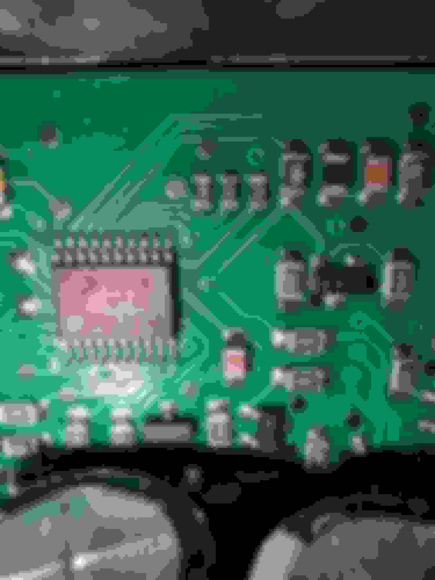
Inspecting the unit it actually looks very promising....
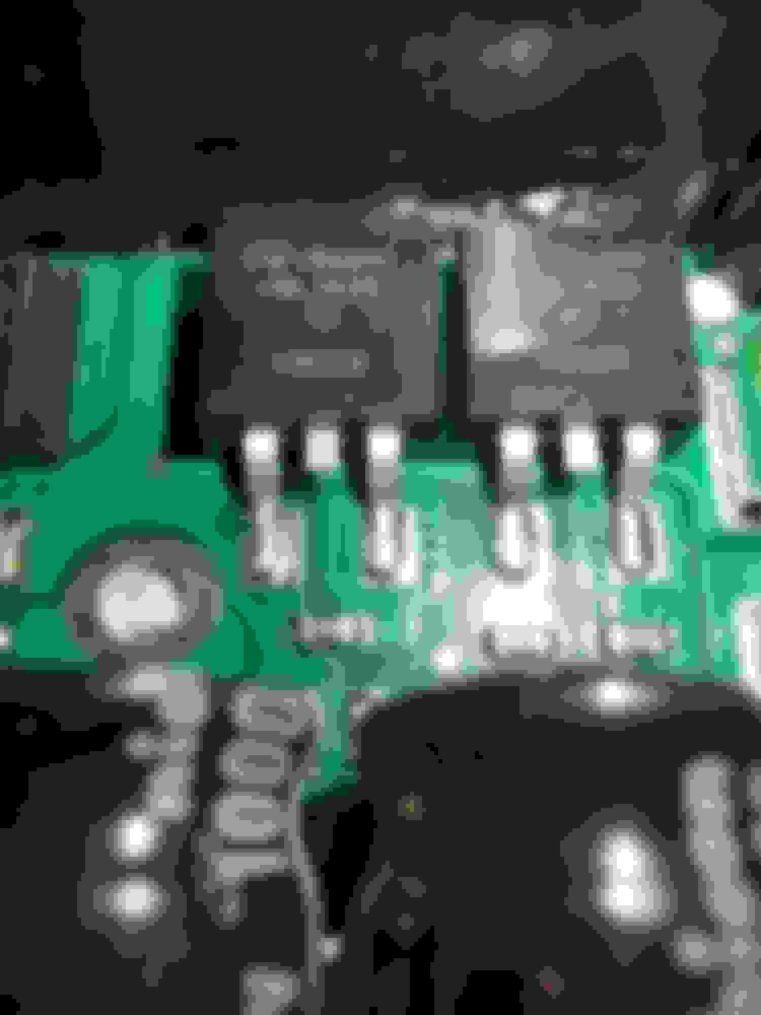
If online spec sheets are right that's an 8 bit microcontroller. FET's look like they're up to the task (I'll assume the three FET's are running parallel) and a nice juicy Shottky diode on the output. So far so good (I was expecting a rats nest of hand soldered wires to a TO-3 hehehhe).
I don't have my bench top power supply yet, so I had to do the initial tests in the car. Also my cooling system is incomplete, so I couldn't do it with the car running. Therefore this test is purely a battery only supply. I charged the battery overnight to start from Max voltage. It was around 12.7 volts if I'm right.
I don't have my Derale fans yet, so I hooked up the twin fans and shroud mounted to radiator from my Toyota 86. To understand total current draw without any controller in the mix I put them straight to battery. They drew 13.90 amps total.
After this then I wired in the Crown Vic controller. Simple 12v in, fan out, and the centre pin on the input connector straight to the e38 pin X1 58.
Power everything up, connect hptuners and start varying the fan speed through that.
Hey presto, vary the fan speed and this is what the output was looking like....
Very low duty cycles in (eg 6 to 10%) and the output of the controller acted accordingly with low duty cycle output, fan running at slow speed etc. It wasn't until I got to about 8% speed in hptuners did the fans actually start moving, however at 6% there was still a waveform on the output of the controller. Sorry but my scope is pretty dumb and won't read duty cycle.
I then headed up the top end of duty cycle. Interestingly, at a certain point of input duty cycle the output waveform will switch from pwm to pure DC (or at least it looks this way on the scope). At the start of the test this was as at around 76% input speed. The according output waveform looked very close to 100% duty cycle at that stage, even though I was only pumping 76% in. If I notched it up to 77% the visible waveform all but disappeared and it looked like a 100% dc voltage. The voltage at this point was no different to the top edge of the pwm waveform when it was pumping out pwm.
I also noticed this switch from pwm output to DC output started to drop during the course of my test. So for example after a while it was a difference between 74/73% input cycle and then later it was the difference between 70/69% where the tipping point was. This was after about 25 minutes of testing, and as the battery voltage was now dropping, I can only assume that this tipping point is purely related to the operating voltage. So I am hoping once the engine is running (or I get my 13.8v bench top supply) that I will be able to do this test again and hopefully the tipping point between outputting pwm versus what looks like dc will happen at a higher percentage point of input duty cycle. I'm hoping at correct operating voltage of 13-14v that it might be something like 85-90% input cycle where this occurs. However that is just an assumption for now.
The two fans through the controller were pulling 13.8 A at Max speed and that was even after the voltage of the battery had eroded a bit.. That was a good sign.
I measured the temp of the heatsink where the FET's are closest. In 25 minutes the highest it ever got was 32.1 degrees C.
So this is a good sign, that it ran incredibly cool at close enough to 14 amps.
I don't have my derale fans yet, so I couldn't load it up any more just yet. I tried adding a light bulb for extra load however it only ran for a second or two then the controller completely shut off. I think this is a protection mechanism the controller will have because a bulb is a resistive load, not inductive (perhaps a "short circuit" mechanism but this is just wild guess). My target is to run one derale fan off one controller. The fan uses 22 amps (or so the spec says). So considering the test on this controller is basically running at room temperature on 14 amps then I'm very hopeful there is plenty of headroom left to handle my target and then some.
In terms of how quickly the output reacts to varying input duty cycles this is hard to know at this stage. The e38 pwm output can be a little slow itself when setting/adjusting the percentage/duty so whenever I went up and down the percentages the output speed did take a second or two to speed up and slow down. Once I get my bench top supply and frequency generator I will be able to test a little more conclusively on reaction speed. What I do know is that the controller wouldn't seem to be adding any massive degree of delay, certainly no more than how the e38 pumps out its pwm.
In terms of output resolution, stepping from 8% to 76% input pwm in one percent increments accordingly puts out the correct duty cycle at the output also with close enough to 1% increments. There were no "steps" or staged output speeds to speak of. (eg there was no "8 to 18% input pwm equals just one output speed of 20%" ). Note though what I said earlier, the 6 to 76% input range did scale the output from close enough to 5% through to about 95% output before flipping to DC output at the top end. So this isn't exactly" 1% variance in equals 1% variance out" however it is close enough and as I said earlier I hope this becomes more accurate when I get it to correct operating voltage circa 13.8 volts.
Output pwm frequency is 19.4 Khz at all varying duty cycles, which is great. My input frequency is set at 128 Hz. I tried 500Hz, 1khz, 9,33 khz and the controller still behaved the same way. I tried 50hz and it seemed unstable. I tried 80 Hz and it behaved. So who knows the exact tipping point but I'd say stick to an input pwm of 100hz or more and you'll easily be fine.
So all of this is pointing to a decent enough job being performed by the onboard 8 bit microcontroller. The resolution, speed and 19.4khz pwm output all point to a great solution for a radiator fan. Depending on how quickly it reacts, it could well be good enough for fuel pump controller too, however that is my next test and won't be able to do this until I get my power supply and frequency generator (also AliExpress jobs hehehe...).
Nice job. That Mosfet is rated at 100A cool and 60A Hot.
Nice that there are no steps.
There will have to be some delay because the controlling frequency is 100HZ and it will need to take a few cycles at a different input PWM to react to the change, so my guess the response won't be faster than 20ms. Did you by any chance try it with a potentiometer instead of a PWM input?
No, didn't try a pot sweep. Do you mean no pwm input, just a plain old pot from pwm input to ground? I'll give it a go when I get my power supply.
What would you like me to try? 1k ohm?
One thing I did try was taking the input and putting straight to ground and also straight to 12v. Neither of these got an output. However, when going to ground, if I made the connection very scratchy or rhythmically tapping it to ground like on/off/on/off to ground let's say similar to a 50% duty cycle per second, then yes the fans started to move. I didn't keep that up for any more than a say 5 seconds though, thinking I may have been causing more trouble than good. Given that result, I'd say I don't like your chances on a pot input doing anything. Still, I will do it when my supply arrives.
Another interesting idea I had was to connect an arduino to a 100k ohm digital pot module. Delete bootloader so arduino starts relatively instantly, then connect the digital pot output to any old generic motor speed controller. Input to arduino is the 128Hz pwm output from the e38.
There is a whole pile of elcheapo ebay Aliexpress dc motor speed controllers out there that use a simple old 100k pot for speed control. This way, with arduino and digital pot module, you could effectively have a controller for any of these off the shelf controllers, big or small, and all you need to do is rip out the pot from the controller and connect the digital pot outputs. Apparently the digital pot modules have a 100 step array so whilst it is not linear 0 to 100k ohm, it still has 100 steps of resolution which is more than enough and would work well enough mapping 1% pwm in to the first resistance level, 2% to second resistance level and so on.

 09-04-2021, 06:33 PM