When you click on links to various merchants on this site and make a purchase, this can result in this site earning a commission. Affiliate programs and affiliations include, but are not limited to, the eBay Partner Network.
Variable Speed PWM Fan Control under $25 or less DIY
This thread has gotten really big and it's pretty hard to find stuff, so I'm adding an index to key posts.
Post Number) Topic.
1) Arduino controlled fan using a Mistubishi PWM fan module, Arduino Nano and a standalone NTC sensor.
3) ECM controlling Mistubishi PWM fan module.
9) Photo of Arduino connected to Mistubishi PWM fan module and adruino code on post 10 and 11.
20) Holley Dominator controlling Corvette C6 / Ford PWM module.
30) Corvette C6 / Ford PWM module description.
40) Corvette C6 / Ford PWM module override input from ECM and set manual fan setting.
63) Jeep PWM fan Module discussion
65) Dorman 902-310 discussion
78) Terminator X PWM - and PWM+ discussion
106) Corvette C6 / Ford PWM module connectors.
125) a pre packaged temperature sensor and fan control.
129) BMW Brushless fan with integrated PWM controller
145) SPAL brushless fan information
157) Ebay fan controller and PWM geneartor
159) Source vehicles for various fans.
181) BMW Brushless integrated PWM fan.
190) Arduino controlling brushless integrated fans or Corvette C6/Ford module to conventional fan (with software).
198) Temperature Sensor discussion.
199 and 207) Arduino and existing temperature sensor controlling BMW brushless, or Volvo Brushless or C6 module.
230) C6/Ford PWM module, Seperate temp sensor, A/C
253) Chevy volt dual PWM fans
256) Volvo brushless Integrated PWM controller fan and list of donor cars and years.
325) some other fan modules and connectors.
340) Mazda/Mitsubishi module connectors.
346) arduino and mitsubishi module connected to existing temp sensor.
348) Running a brushless, soft start, pwm controlled fan, in a dumb car has a fan on/off relay or single wire temperature switch.
391) GM ECM with 2 speed pin 42 - 33 for a Single fan with soft start and adjustable low speed setting. Uses Mazda/Mitsu module. No PWM needed. Can add a second fan also.
396 - 398) Sample code to read AEMnet CANBUS multiple sensors and operate fan PWMs accordingly.
440) Mercedes fan and PWM module with A/C code and schematic.
470) Holley Racepack CANBUS DIY for controlling fans (or anything else)
472) Jeep Pentastar Brushless fan and stock GM coolant sensor
502) BMW brushless (probably most brushless) fans and A/C clutch input.
I'll update the index as interesting or useful posts come up
Here is the start of the original post:
I've gotten alot of useful info from the forum (especially for my transmission) and I thought I'd give something back.
When building my turbo project, I realized I needed a number of fan controllers, especially for the oil cooler because of the extra heat from the turbo and one for the transmission cooler, radiator and intercooler. Since it's a driver and a strip car, I didn't want relays turning the all those fans on and off at full blast all the time. It's noisy and draws way to much power. My car has 6 fans and 2 fuel pumps, all PWMed. I've taken some piece-parts of my solution and incorporated into this fan controller DIY.
I'm providing a parts list, schematic and software that was tested on my bench. Here's the disclaimer. No warranties. Mistaeks are possible. I'm not in business. I'm not selling anything. It's a design and software that anyone can use as a jumping off point. Although this is standalone, I'm pretty confident that parts of this can even more easily be used with any PCMs that can output a PWM. I've got a feeling the the majority of people will add this to their PCM instead of making it standalone.
All the parts needed for a standalone are a processor, a temperature sensor, a fan power module, 2 resistors and some wires and connectors.
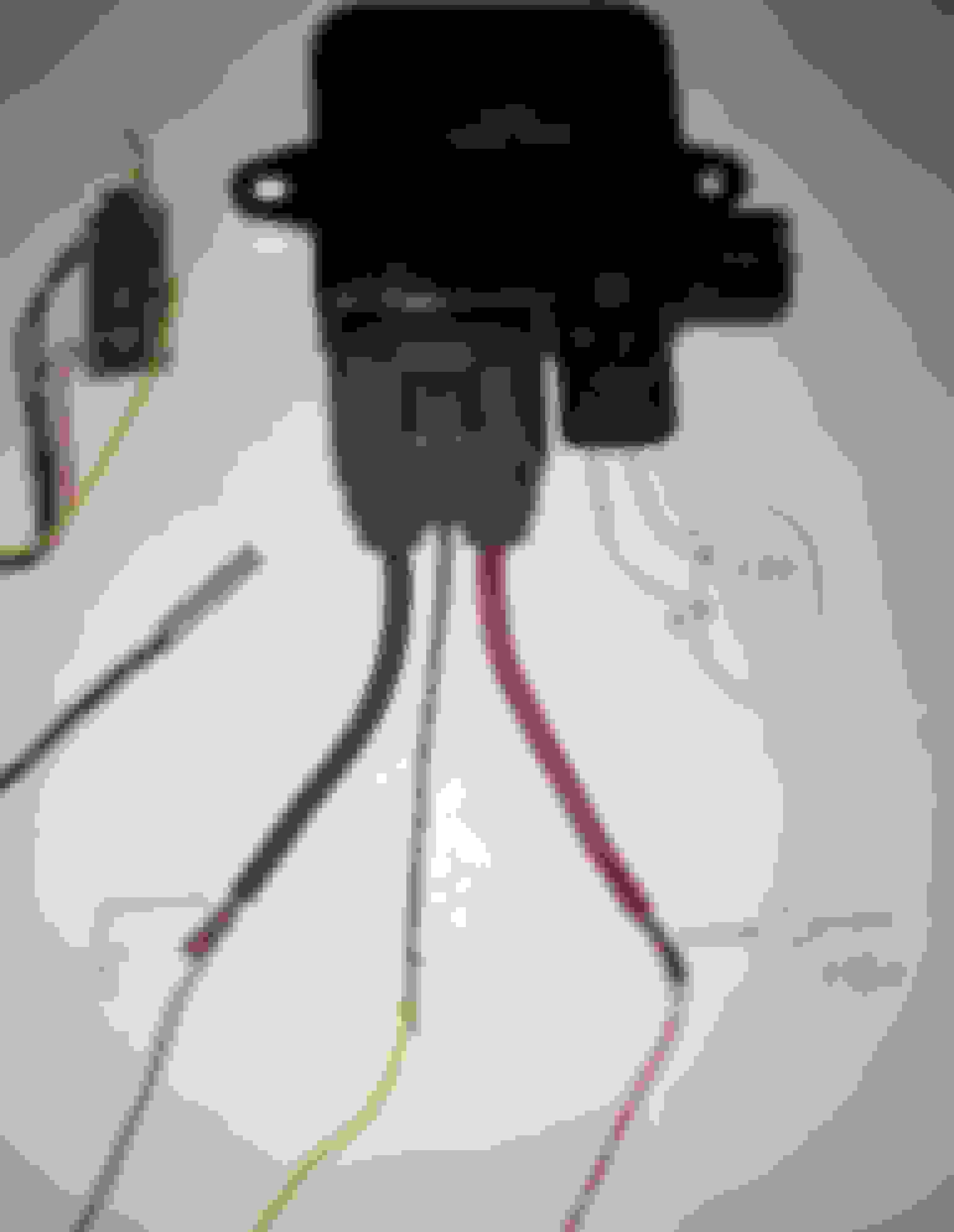
The real key part is the fan power control module. It does all the grunt work of converting the puny signal from the processor or PCM into high power control of one or two fans.
I've seen some people use late model Vette modules, but they are very expensive. While looking around, I found this very inexpensive module used in millions of Mazdas and Mitsubishi's to control both radiator fans. I got mine brand new on Ebay, from a USA seller for $14.
Here's the lowdown on the fan power control module. Everything I know about this fan control module is based solely on my testing, not actual knowledge or documentation, so it may or may not be accurate:
I got one delivered, took it apart, the first thing I noticed is that it has it's own internal processor and software, not user modifiable to my knowledge.
Since it has it's own processor, it controls the PWM frequency to the fans and that's always 20,000hz so the fans run very quietly at any speed.
It is controlled through a single wire. (and ground of course). The center (thin gauge) signal wire, on the big connector, accepts any voltage from 0 to 5 volts or a PWM at any frequency over 50HZ. (I've tested down to 25HZ, but it was a little jumpy).
The power module averages out the PWM inputs so it looks like 0 to 5 volts internally.
No matter what the PWM frequency to the signal wire, the output PWM to the fans is always at 20,000HZ.
The internal processor translates the input signal into one of about 15 different fan speeds. The slowest speed starts at about 1.2V or 24 percent duty cycle on the signal wire. Full speed is at 5 volts or 100 percent duty cycle.
The controller gently ramps the fan speeds up and down to get the fan to eventually match the speed dictated by the signal wire.
The power module has about a 4K ohm, internal pullup to +5 volts, on the center signal wire. If the signal wire is not connected or left floating, the internal pullup will make the fans go to full speed. Probably designed that way as a fail safe.
For a standalone using an arduino as a processor, a 680 ohm resister from the PWM output to ground keeps the fans turned off while the arduino, boots up or the PWM pins are floating for any reason. That should bring the signal wire voltage down below the 1.2V trigger. If used with a PCM or other aftermarket engine management, the connection to the module may be different and I'm pretty sure that will be gone over later.
If the arduino is disconnected from the Mazda module, the fan will ramp up to full blast as a fail safe.
(interchange codes for the Mazda/Mitsubishi module are: 1355A124, 1355S124, 1355-A124, 1355A125, 1355A053, 1C232-19700, AJY215SC0, AJ51-15-15YA, AJY2-15-SC0, 1C23219700, MR497751)
What really impressed me is that the wire gauge on the + and - feeds to the module are 10 gauge. I picked up 4 sets of connectors from a pick and pull for $10. Most of them were in a pile of broken radiators with bent fans. On most vehicles I've seen using this, the module is mounted on the fan assembly.
Here is the schematic for the base standalone i've had running on my bench.
Last edited by LSswap; Oct 19, 2023 at 12:37 AM.
Reason: added index
I suspect most PCMs and aftermarket ECUs that can output a PWM use a mosfet that "sinks" to ground. If this is the case, then hypothetically, one needs only this: Can't get any simpler.
I say hypothetically, because I haven't tested it, but I suspect that the internal pullup in the Mazda fan power module, combined with the sink of the PCM will be enough to make it work just fine. Worst case, an extra pullup resistor can be added to pull the signal wire up to 5V. This makes it very easy to interface with a PCM since one doesn't need a standalone processor, program or temperature sensor or a big wallet.
If instead, the PCM's PWM port outputs 0 to 5 volts, then it can be connected like the arduino diagram. If the PCM outputs 0 to 12 volts, then it will have to be a different connection, but dooable in my opinion.
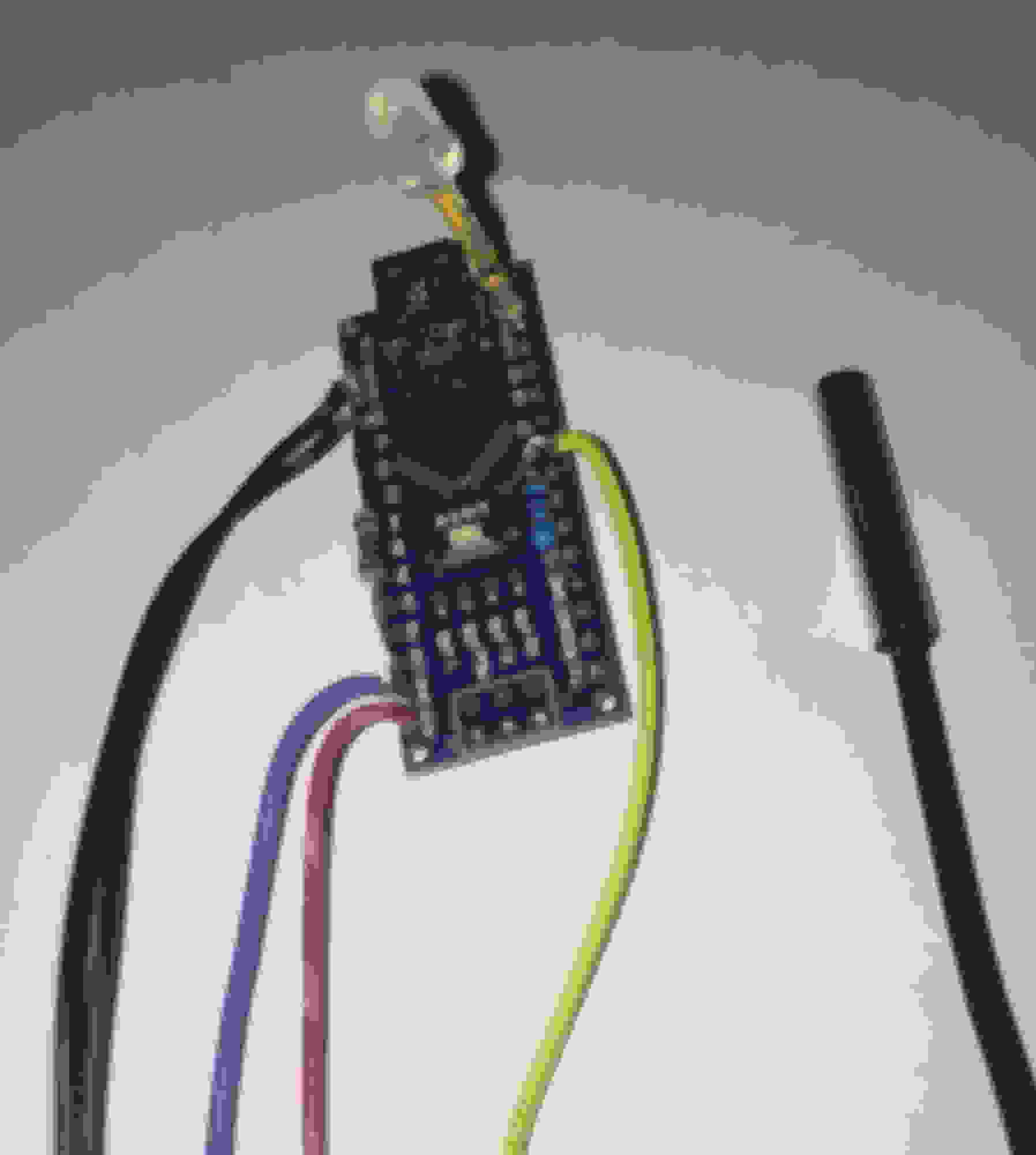
Here is a wired and programmed arduino nano board. Doesn't look like much but there's a whole bunch of untapped power in there.
Notice the 10K resistor and the 680 ohm resistors are wired right at the board. The Red wire is for +12V, The Blue wire is Ground. The Yelllow wire is the PWM out to the power module's signal wire (center small wire on the mazda connector) and the two Black wires are for the temperature sensor. Throw it in a plastic box ant you're good to go.
Anybody notice what wasn't in the original parts picture?
This board had an extra LED installed. It's a bi-color LED. One color is green (would have liked blue, but green is what I had on hand) and the other is red. Why? When the temperature is below the low trigger, the LED is solid green. When the temperature is above the highest trigger it is solid red. When it's in between, the LED alternates between green and red. The more green, the slower the fans are turning, The more red, the faster they're turning. Effectively, it's a poor mans temperature gauge. It could be pretty useful.. Let's say you set reasonable target temps and everything is calibrated. If It's solid Red most of the time, it could be that your cooling system is inadequate.
that module looks like whats on my evo.
pretty neat its usable like that.
Yeah, evo is a good pedigree. Ever have any problems with the fan module? Is it running 1 or 2 fans in your car?
I kinda like the "Frankenstein" model. Using the best parts from other brands to make your own. If I hadn't started on my Vette project (in sig below), I would have built a BMW E30 with a Ford rear, GM trans and SRT4 turbo engine. Come too think of it I have a Ford rear in the Vette.
Some of the fan module connectors that I found had had different colors for the wires, so just be careful and pay attention to the location of the wire rather than the color.
// This a test program, no warranties are implied or given. fanControllerR2V3base
// Use, copy any modify this test program any way you want, at your own risk.
// Test, test, test and then test some more..
// It reads a temperature sensor and controls a Mazda PWM fan power module.
// ...Carl...
/*----------------------- User adjustable variables and preferences section ---------------------------------*/
float tempForFanStartup = 175.0; // target low temp. below this temperature, the fan will be off
float tempForFanOnFull = 210.0; // target High temp. above this temperature, the fan will be on at full power
// adjust these two to get the desired range. for example for a transmission, maybe 140 to 160
float R0 = 10000; // The base resistance of the NTC sensor used. 10K with a 3435 Beta.
float Beta = 3435; // The Beta of the sensor used. Very commonly available
float voltsForFanStartup = 1.2; // Roughly the signal voltage that triggers the mazda module's slowest speed.
// A higher voltage here will effectively increase the fans lowest speed target.
/*----------------------- end of User adjustable variables and preferences -----------------------------------*/
const int fanPwmOutPin = 6; // Arduino forces this pin to 0 or 5 volts.
const int tempSensorPin = A0; // Pin to read analog voltage from the temp sensor.
int pwmDuty; // The calculated PWM duty is stored here
float pwmMinStartupDuty; // the starting duty is stored here (mazda module starts fans at about 24 % duty)
float currTemperature; // the temperature in F is stored here
void setup() { /* ++++++++++++++++++ Setup is run once when the arduino boots ++++++++++++++++++++++++++*/
Serial.begin(115200); // set up serial port for 115200 baud (optional)
analogReference (EXTERNAL) ; // note, this is using the 3.3 volt supply as the analog reference.
analogRead (tempSensorPin) ; // a couple of reads to give the A/D time to adjust
analogRead (tempSensorPin) ; // a couple of reads to give the A/D time to adjust
analogWrite(fanPwmOutPin, 0); // turn the fan off at start
pwmMinStartupDuty = (voltsForFanStartup / 5.0) * 255.0; // convert the Mazda starting voltage to a PWM duty
} // end setup
//print_to_serial_port(); // un-comment this line for testing and calibration to the laptop.
} // end main loop
void calculate_and_send_PWM() { /* ++++++++ subroutine to calculate and set PWM duty cycle ++++++++++++++*/
if (currTemperature < tempForFanStartup) { // If the temperature is below the lowest setpoint, turn fan off
analogWrite(fanPwmOutPin, 0); // PWM duty = 0 percent
pwmDuty = 0;
return;
}
if (currTemperature > tempForFanOnFull) { // If the temperature is above the highest setpoint, turn fan on full
analogWrite(fanPwmOutPin, 255); // PWM duty = 100 percent
pwmDuty = 255;
return;
}
pwmDuty = (int) (pwmMinStartupDuty + (pwmDutyPct * pwmRange) +.5); // actual PWM duty is calculated here
if (pwmDuty > 255) { // make sure duty ended up between 255 and 0
pwmDuty = 255;
}
if (pwmDuty < 0) {
pwmDuty = 0;
}
analogWrite(fanPwmOutPin, pwmDuty); // write PWM duty to PWM output pin
} // end calculate_and_send_PWM
void readAndTranslateTempSensor() { /* ++++++ subroutine to read and translate temp sensor to temp F +++++++++++++*/
int tmp = analogRead(tempSensorPin);
float r = ((1023.0*R0)/(float)tmp)-R0;
currTemperature = Beta/log(r/0.09919) - 273.15; // for a 10K thermister with a beta of 3435
currTemperature = (9.0/5.0) * currTemperature +32; // convert to Fahrenheit
} // end readAndTranslateTempSensor
void print_to_serial_port() { /* ++++++++++ optional prints values to laptop usb port for debugging and calibration ++*/
Serial.print(F("currTemperature F: ")); Serial.print(currTemperature);
Serial.print(F(" pwmDuty: ")); Serial.println(pwmDuty);
}
For those of you computer and controller newbs who have heard about arduino and think that it's only good for a blinking light..., here ya go. Something real, inxpensive and relatively simple to get your feet wet.
Unfortunately when I uploaded the program, the forum changed the spacing. That shouldn't make any difference except to the readability. PIA. Just to make sure it didn't change anything else, i copied the code directly from the post and popped it back into the nano. Still works fine.
thanks for posting this up... the ingenuity of hotrodders never ceases to amaze me...doesn't hurt to know your way around electronics
Thanks. Here is he sick part:
Knowing your way around electronics is similar to knowing your way around turbocharging. With turbos... it's more boooost. With electronics... it more features.
We're never happy with just the basic boost or basic features. Always gotta add more and more.
Unfortunately, i have both the turbo and electronics diseases. Well, maybe not so unfortunate.
Oh yeah, I forgot to mention. If you get a hold of one of these mazda/mitsubishi fan modules, they are really easy to test in your car or on the bench without any electronics!!!.
First hook a fan to the fan connector.
Then connect the battery and ground to the big fat red and black wires (maybe other colors in some cases). That's all. Leave the signal wire unhooked. The fan should ramp up to full speed. Now If you ground the signal wire, the fan will ramp down to off. If you're like me, you will do this over and over cause it's cool the way the module ramps the fans up and down.
Yeah, evo is a good pedigree. Ever have any problems with the fan module? Is it running 1 or 2 fans in your car?
I kinda like the "Frankenstein" model. Using the best parts from other brands to make your own. If I hadn't started on my Vette project (in sig below), I would have built a BMW E30 with a Ford rear, GM trans and SRT4 turbo engine. Come too think of it I have a Ford rear in the Vette.
just one fan.
ive heard of them failing on evos.
any idea what kind of current they can handle?
this is interesting because theres basically zero information about these modules on the evo boards, im happy to see someone dug in.
My silverado fans run on standard relays using the oem schematic and they pull a ton of current at power on. it would be nice to smooth that out.
when you pulled them apart is there some sort of hardware rc circuit that converts the pwm signal to voltage or is there an IC in there that just seems to control the output using either input method?
just one fan.
ive heard of them failing on evos.
any idea what kind of current they can handle?
No Idea about the max current, but I had it on 2 radiator fans, no problem whatsover. I also ran it for a while on my Walbro 450 fuel pump at 80 psi. No probelm, Barely got warm.
The only thing I didn't like about them is when I opened it up, There are two screws holding the mosfets to the heat sink. They weren't very tight, which may not be that bad..... however, I,m concerned that they may back out with vibration. So I'm thinking about snugging them up and dabbing a bit of glue on the heads to keep them from turning and getting loose over time.
Originally Posted by TrendSetter
when you pulled them apart is there some sort of hardware rc circuit that converts the pwm signal to voltage or is there an IC in there that just seems to control the output using either input method?
Hard to tell with surface mount. I'd guess there's and R/C in there up front, but the rest of it is done by a complete computer chip inside.
Since extra features don't cost real money, it's nice to throw in bells and whistles. Stuff like:
An LED to let you know how hard the fan is being driven.
A high temp alarm.
An air conditioning input to turn the fans on even if the temps are low.
Maybe a digital temperature readout.
Maybe control for the oil cooler as well as the trans cooler.
Maybe a track mode where you want things cooler.
Maybe temperature setpoints adjustable on the fly.
Maybe turning the fans off when the engine is cranking.
Maybe bluetooth to cellphone.
There is no end to it. Once you get comfortable with it, you're like a kid in a candy store. Once you add a feature and you get a brainstorm.... JUST ONE MORE!!!!.
I have used the C6 Corvette fan controller on my Cougar for years with the Holley Dominator. The C6 controller is much bigger and is about $100, although the Ford Fusions used the same controller and those can be found cheap in the junk yard. Just as an FYI, since you like to tinker, the C6 controller works with a fixed 128Hz input.
Gas Monkey Built a 6-Wheel Ferrari Testarossa With a Corvette LT4 Engine
Slideshow: The controversial Ferrari F6 swaps its original flat-12 for a Corvette Z06-derived LT4 V8 and sends power to four rear wheels through a custom-built drivetrain.
7 Most Reliable High-Performance Engines GM Has Ever Built
Slideshow:These GM engines didn't just make huge power, they survived abuse, boost, track days, and six-digit mileage with a reputation for refusing to quit.
6 Common C5 Corvette Failures and What's Involved In Repairing Them
Slideshow: From wobbling harmonic balancers to failed EBCMs, these are the issues that define long-term C5 ownership and what repairs typically involve.
Retro Modern Bandit Pontiac Trans AM Comes With Burt Reynolds' Autograph
Slideshow: A modern Camaro transformed into a retro icon, this limited-run "Bandit" build blends nostalgia with brute force in a way few revivals manage.
Top 10 Greatest Cadillac V Series Performance Models Ever, Ranked
Slideshow: Cadillac didn't just crash the high-performance luxury vehicle party, it showed up loud, supercharged, and occasionally a little unhinged...
Coachbuilt N2A Anteros Is an LS2-Powered C6 Corvette In Italian Clothes
Slideshow: A one-off sports car that looks like a vintage Italian exotic-but hides a C6 Corvette underneath-just sold for the price of a new mid-engine Corvette.


 Nice work! I love these kinds of mods.