When you click on links to various merchants on this site and make a purchase, this can result in this site earning a commission. Affiliate programs and affiliations include, but are not limited to, the eBay Partner Network.
just an update on the common mitsubishi/nissan etc controller : the oem controller use NEC chip there are only two rows of writing on them:
c5202 920 first line, second line 0452C3001
I suspect the c5202 identifies the chip but not sure. Cant find datasheet still.
Thanks to Mustang 5L5 for doing a teardown and confirming this info.
what current is the mazda controller (first post) rated for? (sorry, i havent read the whole thread.)
I have read the thread, and don't think the amp capacity of the Mazda/Mitsu controller has been discovered.
Unless of course LSswap has since made such a discovery. I'm kinda curious about it myself....
I have read the thread, and don't think the amp capacity of the Mazda/Mitsu controller has been discovered.
Unless of course LSswap has since made such a discovery. I'm kinda curious about it myself....
Yeah, I don't know the amp rating. I used in it my vette for over a year with two fans on the radiator as well as 2 fans on the intercooler, with no failures. I've seen two fans driven by it in the JY.
I also use it with single smaller fans for trans cooler and oil cooler. I've switched over to single a Brushless fan for the radiator.
Somewhere early in the thread you mention having beat the crap (or similar) out of the Mazda/Mitsu unit, unless I'm taking something out of context.
Do you think one can handle 05-12(??) GM truck twin fans?
for that i would run two and just tie the signal lines together so they run the same. those brushed fans pull a lot of current, but the pwm ramp up may allow it to survive.
for that i would run two and just tie the signal lines together so they run the same. those brushed fans pull a lot of current, but the pwm ramp up may allow it to survive.
Not against using 2 boxes, just that its 2 fan ports would make such a clean wiring job. Maybe the slower rampup would save it, but until I hear about one handling the load of the GM truck fans, I will abstain from using it.
This has given me big hope for my Supercharged car that really needs a new fan setup.
Ive been reading through, I am not computer savvy like a good bit of the people posting here so I have a question - With that fan, with an integrated PWM controller, if I have an ECU that will output a PWM signal, I wouldnt need a control board/arduino in-between?
If you want to use the factory bosch sensor, then you need to have two additional pieces of information.
1) the table of resistance to temperature translations.
2) the series resistance and voltage applied to that resistor inside whatever is reading the temperature now.
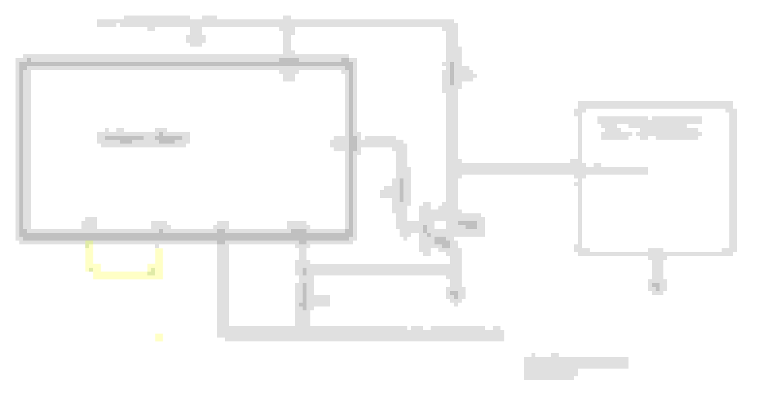
In the mean time, I'm going to post a schematic and code for testing your BMW PWM fan using an external temperature sensor. This is the same code that would be used with the Bosch sensor except for the routine that reads and translates the sensor.
@LSswap if you've still got it can I be really cheeky and get the code above as text please. Save me a few mins. I'm going to give it a go with a generic Arduino kit 10K thermistor poked in the rad fins with some heat paste. I'm over in the UK BMW fans are about the cheapest Vs CFM you can get in parts yards! :+)
@LSswap if you've still got it can I be really cheeky and get the code above as text please. Save me a few mins. I'm going to give it a go with a generic Arduino kit 10K thermistor poked in the rad fins with some heat paste. I'm over in the UK BMW fans are about the cheapest Vs CFM you can get in parts yards! :+)
For you across the pond, just take out the stupid conversion to Fahrenheit and adjust your target temps to degrees C.
// This a test program, no warranties are implied or given. PWM BMW ext temp sensor V1
// Use, copy any modify this test program any way you want, at your own risk. Then test, test, test
// It reads a extermal 10K thermister temperature probe and controls a BMW PWM fan.
// BMW fan: 5% duty = full, 95% = off, no PWM = full Freq = 100Hz, PWM signal is 12 volt, Temps in Centigrade
#include <PWM.h>
/*----------------------- User adjustable variables and preferences section ---------------------------------*/
// FYI a PWM duty ranges from 0 to 255. Set desired temperature range below
const int tempForFanStartup = 74; // target low temp. below this temperature, the fan will be off
const int tempForFanOnFull = 99; // target High temp. above this temperature, the fan will be on at full power

// adjust these for PWN to for fan off, fan start and fan full on
const int fanOnFullDuty = 26; // duty for 10% (full speed = 10% of 255)
const int fanDutyOff = 242; // duty for 95% (off fan speed = 95% of 255)

/*----------------------- end of User adjustable variables and preferences -----------------------------------*/
const int fanPwmOutPin = 9; // Arduino forces this pin to 0 or 5 volts.
const int tempSensorPin = A0; // Pin to read analog voltage from the temp sensor.

void setup() { /* ++++++++++++++++++ Setup is run once when the arduino boots ++++++++++++++++++++++++++*/
Serial.begin(115200); // set up serial port for 115200 baud (optional)
InitTimersSafe(); // set pwm frequency to 100 Hz for BMW pwm
SetPinFrequency(fanPwmOutPin, 100); // set pwm frequency to 100 Hz for BMW pwm
pwmWrite(fanPwmOutPin, 0); // start with fan off
analogReference (EXTERNAL); // note, this is using the 3.3 volt supply as the analog reference for more accuracy.
} // end setup

void loop() { /* ++++++++++++++++++ Main Loop, continuously loops forever ++++++++++++++++++++++++++++*/
int currTempC = get_temperature_sensor(); // read and translate the temp sensor
int pwmDuty = calculate_PWM_duty(currTempC); // calculate the needed pwm
pwmWrite(fanPwmOutPin, 255 - pwmDuty); // send PWM to output pin (invert pwm for 12 volt transistor)
Serial.print(F("Temp C: ")); Serial.print(currTempC);
Serial.print(F(" pwmDuty: ")); Serial.println(pwmDuty);
delay(1000);
} // end main loop

int calculate_PWM_duty(int currTemp) { /* ++++++++ subroutine to calculate and set PWM duty cycle ++++++++++++++*/
int duty = map(currTemp, tempForFanStartup, tempForFanOnFull, fanDutyOff, fanOnFullDuty ); // calc PWM Duty
int contrainedDuty = constrain(duty, fanOnFullDuty, 255 ); // PWM duty is never allowed ouside of min or max duties
return(contrainedDuty);
} // end calculate_PWM_duty

int get_temperature_sensor() {/* +++++ returns temp for extermal 10K thermister temperature probe ++++++++++*/
float R0 = 10000; // The base resistance of the NTC sensor used. 10K with a 3435 Beta.
float Beta = 3435; // The Beta of the sensor used. Very commonly available
int tmp = analogRead(tempSensorPin); // read temperature sensor (range 0 to 1023)
float r = ((1023.0*R0)/(float)tmp)-R0; // for a 10K thermister with a beta of 3435
tmp = (int) (Beta/log(r/0.09919) - 273.15 + .499); // for a 10K thermister with a beta of 3435
return(tmp);
} // end get_temperature_sensor
@thesameguy My fan didn't come with the car side of the loom (I'm just spade connected onto the pins for now) I don't suppose you have part numbers for the car side of the connector (or did you get lucky and score yours with more wiring) :-)
As expected @LSswap 's code is perfect, I've swapped my low and high temps in, hit verify button and uploaded to my nano clone first try.
I'm using the latest PWM.h library i found from Sam Knight on google code (v5) is this the version you are using.
I've bread-boarded up my nano with a trimpot doing duty as a desktop simulation for the thermistor but alas no movement from the BMW fan blades
I've gone through my bread board a few times to double check myself and tried a couple of transistors from a pack of 2N3904 's in case I had a dud but still no luck.
My "desktop power supply" is really an old pc power supply, it only has 11.6v on its 12v lines, is this enough, I'm wondering if the fan controller has under voltage protection for the battery, or if 11.6 isn't close enough to 12v for the PWM signal?
11.6 is enough. A PWM of 156 should get the fan turning. You need to use a scope and see where your problem lies. If you only have a voltmeter, you should see the voltage (actually the average) increase or decrease, with temperature change, at the PWM out from the transistor and also from the Arduino output pin. You can also use one of those Ebay PWM generators to see if the fan turns.
@LSswap sorted! there was an innocent typo on line30
I've changed >
pwmWrite(fanPwmOutPin, 0);
to >
pwmWrite(fanPwmOutPin, pwmDuty);
clearly at 2am GMT last night my code review talents weren't at their highest vigilance! lol.
Amusingly my BMW fan doesn't seam to have the same responses to the PWM signal as thesameguy's did. I googled the valeo part numbers from his post and it came up the same as the one I've got... though my part number was in sharpie pen on some duct tape not the original sticker! lol. My fan came off an a BMW f20 m135i but is devoid of original part numbers so who knows what it is really / if it was the right one for the car... (it was already removed before i saw it).
I shall have a play to work out the required PWM duties and post my modified code / install pics etc back here (don't anybody hold their breaths it is a project car not one I need to get to work on Monday so I'm not in a rush)
@LSswap thanks again chap, you've saved me a ton of time!
@LSswap sorted! there was an innocent typo on line30
I've changed >
pwmWrite(fanPwmOutPin, 0);
to >
pwmWrite(fanPwmOutPin, pwmDuty);
Good catch. I dropped that in there when I was converting the program to Centigrade for you. It shoud be: pwmWrite(fanPwmOutPin, 255 - pwmDuty); That inverts the signal for the transistor. I fixed it in the code above.
Just in case my BMW fan is what it says it is an is from a m135i and so this info is useful to someone... (I expect not but you never know, lol) my fan turns on at an Arduino (0-255) PWM duty of 29 (~11.7%) and cuts out requiring a power reset at values above 119 (~46.9%) with fan speed increasing audibly (I haven't got a magic speed gun) from 29 to 118 PWM duty values.
Also the f20 M135i fan does not default to on when no PWM is present it needs a valid PWM signal to run.
EDIT: As I've been developing my code I've had a couple of instances of it clicking out while running at 118 PWM duty cycle requiring a reset (118 was my previous set max duty cycle in my code). I assume it has an internal speed signal and it must have gone slightly over speed somehow, I'm going to run my "max" duty cycle at 110 to give a bit of safety margin. It moves a hell of a lot of air anyway I'm not going to need anything near max speed in practice!
Last edited by ad_v8; 05-20-2023 at 08:15 PM.
Reason: adding update that affects posts useful detail
 04-21-2023, 02:47 PM