When you click on links to various merchants on this site and make a purchase, this can result in this site earning a commission. Affiliate programs and affiliations include, but are not limited to, the eBay Partner Network.
First off, much appreciation to all of you for contributing to this thread. It�s been a huge help so far.
wondering if someone can help me figure this out.
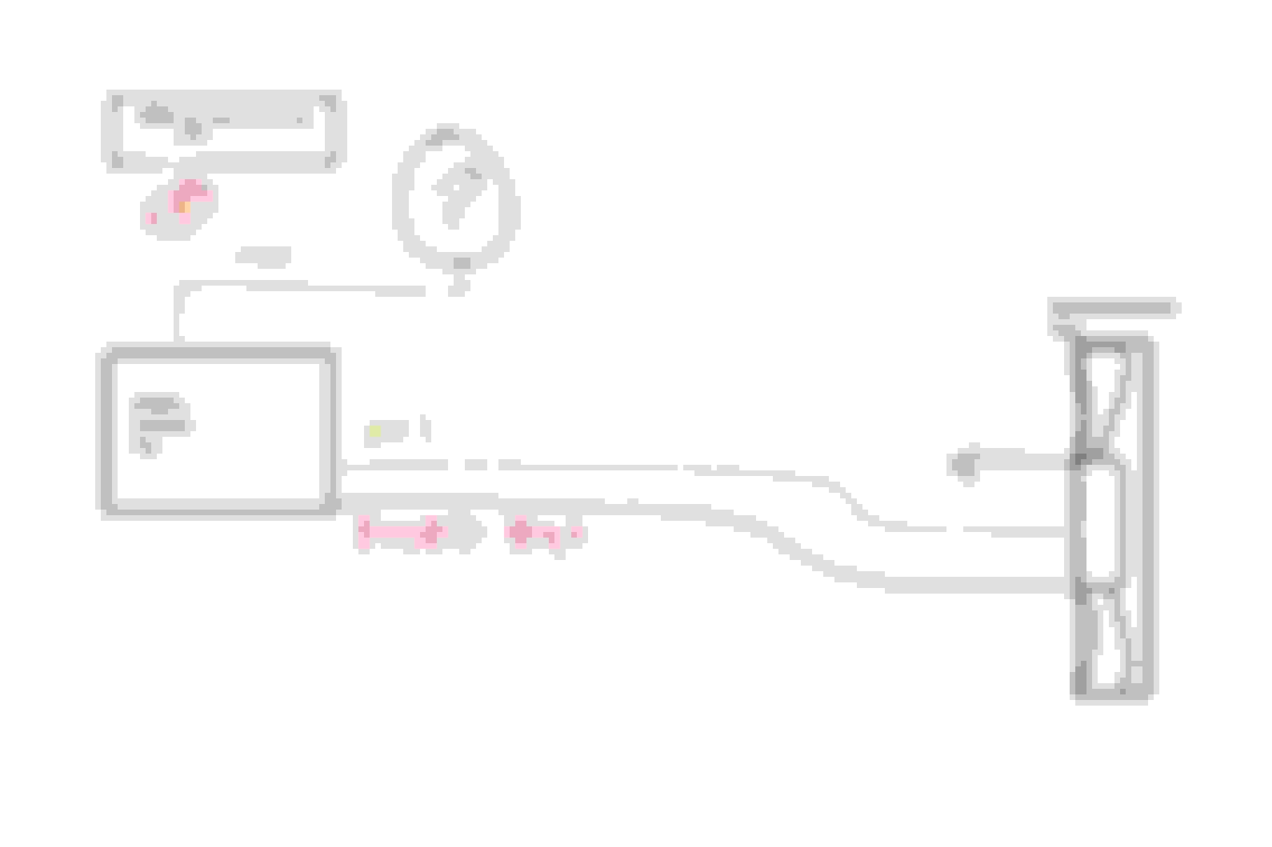
I have Bosch brushless fans that run their power and control wire through their matching Battery junction box. Then control runs up to the ECU, which I swapped out.
what�s confusing me is the control wire coming out of the fuse box is 12v, low mA. My assumption is the old ecu was controlling PMW via -5v (or ground signal PMW via mosfet?)
this is where my understanding is fuzzy� I�d like to keep the power and control going through battery junction box as it already is fused and regulates shorts but that 12v coming from it to the ecu is confusing. Can�t recall exact reading but it�s a very low milliamp 12v signal.
Current existing setup.
So what you're saying is that your current ECU does not have a working PWM line. The you need to decide what alternative is the best one for you.
Does it have a low high relay signal or was it a PWM style ECu and the PWM part is broken?
There are a number of alternatives proposed in this thread that can work for you. The first page has an index to possibly help you hunt down the best one based on your needs and skill level.
// This a test program, no warranties are implied or given. PWM BMW ext temp sensor V1
// Use, copy any modify this test program any way you want, at your own risk. Then test, test, test
// It reads a extermal 10K thermister temperature probe and controls a BMW PWM fan.
// BMW fan: 5% duty = full, 95% = off, no PWM = full Freq = 100Hz, PWM signal is 12 volt, Temps in Centigrade
#include <PWM.h>
/*----------------------- User adjustable variables and preferences section ---------------------------------*/
// FYI a PWM duty ranges from 0 to 255. Set desired temperature range below
const int tempForFanStartup = 74; // target low temp. below this temperature, the fan will be off
const int tempForFanOnFull = 99; // target High temp. above this temperature, the fan will be on at full power

// adjust these for PWN to for fan off, fan start and fan full on
const int fanOnFullDuty = 26; // duty for 10% (full speed = 10% of 255)
const int fanDutyOff = 242; // duty for 95% (off fan speed = 95% of 255)

/*----------------------- end of User adjustable variables and preferences -----------------------------------*/
const int fanPwmOutPin = 9; // Arduino forces this pin to 0 or 5 volts.
const int tempSensorPin = A0; // Pin to read analog voltage from the temp sensor.

void setup() { /* ++++++++++++++++++ Setup is run once when the arduino boots ++++++++++++++++++++++++++*/
Serial.begin(115200); // set up serial port for 115200 baud (optional)
InitTimersSafe(); // set pwm frequency to 100 Hz for BMW pwm
SetPinFrequency(fanPwmOutPin, 100); // set pwm frequency to 100 Hz for BMW pwm
pwmWrite(fanPwmOutPin, 0); // start with fan off
analogReference (EXTERNAL); // note, this is using the 3.3 volt supply as the analog reference for more accuracy.
} // end setup

void loop() { /* ++++++++++++++++++ Main Loop, continuously loops forever ++++++++++++++++++++++++++++*/
int currTempC = get_temperature_sensor(); // read and translate the temp sensor
int pwmDuty = calculate_PWM_duty(currTempC); // calculate the needed pwm
pwmWrite(fanPwmOutPin, 255 - pwmDuty); // send PWM to output pin (invert pwm for 12 volt transistor)
Serial.print(F("Temp C: ")); Serial.print(currTempC);
Serial.print(F(" pwmDuty: ")); Serial.println(pwmDuty);
delay(1000);
} // end main loop

int calculate_PWM_duty(int currTemp) { /* ++++++++ subroutine to calculate and set PWM duty cycle ++++++++++++++*/
int duty = map(currTemp, tempForFanStartup, tempForFanOnFull, fanDutyOff, fanOnFullDuty ); // calc PWM Duty
int contrainedDuty = constrain(duty, fanOnFullDuty, 255 ); // PWM duty is never allowed ouside of min or max duties
return(contrainedDuty);
} // end calculate_PWM_duty

int get_temperature_sensor() {/* +++++ returns temp for extermal 10K thermister temperature probe ++++++++++*/
float R0 = 10000; // The base resistance of the NTC sensor used. 10K with a 3435 Beta.
float Beta = 3435; // The Beta of the sensor used. Very commonly available
int tmp = analogRead(tempSensorPin); // read temperature sensor (range 0 to 1023)
float r = ((1023.0*R0)/(float)tmp)-R0; // for a 10K thermister with a beta of 3435
tmp = (int) (Beta/log(r/0.09919) - 273.15 + .499); // for a 10K thermister with a beta of 3435
return(tmp);
} // end get_temperature_sensor
IT working well with my BMW f21 fan .but could you pls add AC overall 50%of the fan speed ?
THANK YOU VERY MUCH for your help.
Brushless BMW (probably most brushless) fans with A/C input from clutch.
Brushless BMW (probably most brushless) fans with A/C input from clutch.
Code:
// This a test program, no warranties are implied or given. PWM BMW ext temp sensor V1
// Use, copy any modify this test program any way you want, at your own risk. Then test, test, test
// It reads a extermal 10K thermister temperature probe and controls a BMW PWM fan.
// BMW fan: 5% duty = full, 95% = off, no PWM = full Freq = 100Hz, PWM signal is 12 volt, Temps in Centigrade
// also turn fan 0n 50% if A/C is on and engine cold.
#include <PWM.h>
/*----------------------- User adjustable variables and preferences section ---------------------------------*/
// FYI a PWM duty ranges from 0 to 255. Set desired temperature range below
const int tempForFanStartup = 74; // target low temp. below this temperature, the fan will be off
const int tempForFanOnFull = 99; // target High temp. above this temperature, the fan will be on at full power
const int A_C_Start_temp = tempForFanStartup + ((tempForFanOnFull - tempForFanStartup)/2); // set this to 50% of tempForFanStartup and tempForFanOnFull

// adjust these for PWN to for fan off, fan start and fan full on
const int fanOnFullDuty = 26; // duty for 10% (full speed = 10% of 255)
const int fanDutyOff = 242; // duty for 95% (off fan speed = 95% of 255)

/*----------------------- end of User adjustable variables and preferences -----------------------------------*/
const int fanPwmOutPin = 9; // Arduino forces this pin to 0 or 5 volts.
const int tempSensorPin = A0; // Pin to read analog voltage from the temp sensor.
const int AC_ClutchPin = A1; // Pin to A/C Clutch via 1K/10K Voltage Devider

void setup() { /* ++++++++++++++++++ Setup is run once when the arduino boots ++++++++++++++++++++++++++*/
Serial.begin(115200); // set up serial port for 115200 baud (optional)
InitTimersSafe(); // set pwm frequency to 100 Hz for BMW pwm
SetPinFrequency(fanPwmOutPin, 100); // set pwm frequency to 100 Hz for BMW pwm
pwmWrite(fanPwmOutPin, 0); // start with fan off
analogReference (EXTERNAL); // note, this is using the 3.3 volt supply as the analog reference for more accuracy.
} // end setup

void loop() { /* ++++++++++++++++++ Main Loop, continuously loops forever ++++++++++++++++++++++++++++*/
int currTempC = get_temperature_sensor(); // read and translate the temp sensor

if (analogRead(AC_ClutchPin) > 20 ) { // A/C is on
// When the A/C Clutch is On, Voltage > .32V at Analog Input ( is ~ 1.4V when A/C is On )
if (currTempC < tempForFanStartup) {
currTempC = A_C_Start_temp; // Override NTC Temp Sensor Reading with 50% if A/C On & Engine Cold
}
}

int pwmDuty = calculate_PWM_duty(currTempC); // calculate the needed pwm
pwmWrite(fanPwmOutPin, 255 - pwmDuty); // send PWM to output pin (invert pwm for 12 volt transistor)
Serial.print(F("Temp C: ")); Serial.print(currTempC);
Serial.print(F(" pwmDuty: ")); Serial.println(pwmDuty);
delay(1000);
} // end main loop

int calculate_PWM_duty(int currTemp) { /* ++++++++ subroutine to calculate and set PWM duty cycle ++++++++++++++*/
int duty = map(currTemp, tempForFanStartup, tempForFanOnFull, fanDutyOff, fanOnFullDuty ); // calc PWM Duty
int contrainedDuty = constrain(duty, fanOnFullDuty, 255 ); // PWM duty is never allowed ouside of min or max duties
return(contrainedDuty);
} // end calculate_PWM_duty

int get_temperature_sensor() {/* +++++ returns temp for extermal 10K thermister temperature probe ++++++++++*/
float R0 = 10000; // The base resistance of the NTC sensor used. 10K with a 3435 Beta.
float Beta = 3435; // The Beta of the sensor used. Very commonly available
int tmp = analogRead(tempSensorPin); // read temperature sensor (range 0 to 1023)
float r = ((1023.0*R0)/(float)tmp)-R0; // for a 10K thermister with a beta of 3435
tmp = (int) (Beta/log(r/0.09919) - 273.15 + .499); // for a 10K thermister with a beta of 3435
return(tmp);
} // end get_temperature_sensor
thank you bro ,but it work like a temp switch it start in full speed when it cools down the engine it turns off the fan , I see u answer this question and I tried this correction but it makes the fan work always in slow . when the temp increased just as before the fan work in full speed.
Yes, I found the bug. it was within the subroutine that calculates the PWM duty.
statement with error: int contrainedDuty = constrain(duty, fanOnFullDuty, 255 ); // PWM duty is never allowed ouside of min or max dutie
Corrected: int contrainedDuty = constrain(duty, fanDutyOff, fanOnFullDuty ); // PWM duty is never allowed ouside of min or max duties
I'll correct it in the code I posted above.
Here's my question, because what i've tested now is we have only 2 settings for Fanspeed,, Fan off or Fan On Full Speed when it reads 98 Celcius in my example.
Is it possible to have more steps for Fan Speed when temps are increasing ?
I'll load the code into my test setup. More to follow.
There should be more speeds than 2. What PWM is your fan expecting for off, low speed and max speed?
I want to use these fans for my project, they are from an Audi SQ5. I already bought a PWM Generator and tested it. It responds to 10Hz and is off at 10% Duty Cycle, starts spinning at 13%. It's not for an LS car but here is so much info on PWM Fan control that I hope I'm welcome here. What confused me is the wiring, some show transistors and resistors on the PWM line, others don't. What do I need to control these with an arduino? I just hooked up the PWM line from the generator to the fan, nothing in between.
Also with the arduino is there a way to detect charging voltage(14,4V vs. 12V) from the generator? I want to switch some other stuff (water pump and power steering) but only when the engine is running not with just the ignition on.
I want to use these fans for my project, they are from an Audi SQ5. I already bought a PWM Generator and tested it. It responds to 10Hz and is off at 10% Duty Cycle, starts spinning at 13%. What confused me is the wiring, some show transistors and resistors on the PWM line, others don't.
The fact that you got it working with just a PWM generator that is connected to 12V means that your fans control is tolerant of a 0 - 12V PWM signal. Some are a 5V PWM signal and will burn out with 12V PWM.
An arduino only can put out a 0-5V PWM. Arduinos (actually all computers) don't like 12V and need to be protected from 12V. If your fan needs a 0-12V PWM or if your fan needs just an open source sink to the ground and has it's own 12V pullup, then you must use the transistor to both provide the 12V and to protect the arduino from the 12V. If you have only the transistor and no pullup resistor, then it will only be able to sink to ground. If you add a pullup resistor to the transistor, then it can provide a 0 - 12V PWM (and protect the arduino from 12V) The PWM generator actually has in it, a transistor and a pullup resistor to the supply voltage (whatever that voltage is 5V or 12V or any V) and works exactly like the transistor with the pullup resistor.
Originally Posted by miniCotulla
Also with the arduino is there a way to detect charging voltage(14,4V vs. 12V) from the generator? I want to switch some other stuff (water pump and power steering) but only when the engine is running not with just the ignition on.
Sure, however, you can't connect 14.4 or 12 volts directly to the analog ports or it will burn them out. So instead, you would use a voltage divider (similar to the one used in one of the circuits above to detect the A/C compressor). This needs to insure that even though you are reading a maximun worst case of let's say 20V, the arduino never sees more than 5V at the analog port. Then you would scale your reading to the proportion of the voltage divider.
Originally Posted by miniCotulla
I want to switch some other stuff (water pump and power steering) but only when the engine is running not with just the ignition on.
For that you would need to find some voltage that changes when the engine is running. Ideally a 0-5 voltage like a hall effect sensor on the cam or crank. Then you could connect that to one of the digital inputs and check that it's changing from on to off every so often which means the engine is running. If it stays on or off for a long time, then the engine is not running. If you have a VR sensor, then that's much more difficult. You could also use an injector signal, but since injectors are 12V, then you need the voltage divider again and use an analog port.
The fact that you got it working with just a PWM generator that is connected to 12V means that your fans control is tolerant of a 0 - 12V PWM signal. Some are a 5V PWM signal and will burn out with 12V PWM.
An arduino only can put out a 0-5V PWM. Arduinos (actually all computers) don't like 12V and need to be protected from 12V. If your fan needs a 0-12V PWM or if your fan needs just an open source sink to the ground and has it's own 12V pullup, then you must use the transistor to both provide the 12V and to protect the arduino from the 12V. If you have only the transistor and no pullup resistor, then it will only be able to sink to ground. If you add a pullup resistor to the transistor, then it can provide a 0 - 12V PWM (and protect the arduino from 12V) The PWM generator actually has in it, a transistor and a pullup resistor to the supply voltage (whatever that voltage is 5V or 12V or any V) and works exactly like the transistor with the pullup resistor.
Sure, however, you can't connect 14.4 or 12 volts directly to the analog ports or it will burn them out. So instead, you would use a voltage divider (similar to the one used in one of the circuits above to detect the A/C compressor). This needs to insure that even though you are reading a maximun worst case of let's say 20V, the arduino never sees more than 5V at the analog port. Then you would scale your reading to the proportion of the voltage divider.
For that you would need to find some voltage that changes when the engine is running. Ideally a 0-5 voltage like a hall effect sensor on the cam or crank. Then you could connect that to one of the digital inputs and check that it's changing from on to off every so often which means the engine is running. If it stays on or off for a long time, then the engine is not running. If you have a VR sensor, then that's much more difficult. You could also use an injector signal, but since injectors are 12V, then you need the voltage divider again and use an analog port.
guess I was lucky with the 12V PWM
A solution via hall effect sensor sounds more robust. It does have normal hall effect sensors on crank and cam, how do I detect the correct RPM?
A solution via hall effect sensor sounds more robust. It does have normal hall effect sensors on crank and cam, how do I detect the correct RPM?
Ah, so before you only asked to know if the engine is running. Now, you want to know the actual RPM. Scope creep. LOL
Nevertheless, since you have a hall effect cam sensor (assuming it's a 5 volt one) connect it directly to port 2 or 3 on the arduino and set that port as an input. These two ports are special because they support interrupt processing which means that whatever the arduino is doing, it will temporarily leave that to go and do what is in the interrupt routine and then go back to what it was doing. In your interrupt subroutine, record the time that signal went from 0 to 5V. Then the next time the signal goes from 0 to 5v and again triggers the interuupt routine, you can subtract the current time (these are in microseconds, so it's very accurate) from the time you recorded previously and calculate your exact RPM. For the cam, it's often one 0 to 5v transition per revolution. For the crank, it can be many more per revolution, for example a 24 tooth or 52 or lots of other numbers depending on manufacturer. Stick to the cam sensor, it's simpler.
Looks like you're diving deeper into the rabbit hole.
the crank might be simpler on my car as the cam hast multiple different teeth. Maybe I'll just stick to engine running with a few seconds delay instead of actual rpm to keep it simpler.
I took my Fusion controller apart so I could take some pics. See below. I'd like to see what if any differences there are with the C6 and Mercedes controllers. According to the Megasquirt forum post I linked, the Mercedes controller has 8 gauge input wires while these on the Fusion are 10 gauge. That being the case, it would seem the Mercedes internals would have to be heftier. I'm not great with circuit boards, but it looks like the two smaller terminals on each side are not connected to anything.
After reading his posts again, it seems like if you can delay the ignition power input to the MB controller until after it gets a PWM signal, it works properly. I found a 12V relay with an adjustable delay time that could possibly work for this.
Sorry to drag up an old thread but it is a beauty!
I'm in Australia and looking to use a Mercedes module because it's more likely I'll be able to find one at a wrecker and my SPAL fan (VA01-AP90/LL-66A / upto 38amps) is likely going to exceed the power handling capability of the Mazda/Mitsu modules first mentioned in this thread.
I've noted for the Merc units, the PWM pin on thier labels shows it is the top left pin and the center pin is labelled pin#15, whereas for the C6 units the labels show the PWM pin is the center pin and the top left pin is unused.
Sorry if this has been answered but I couldn't find with a quick search. When using the Merc module, do I ignore Pin#15 and just put the PWM to the top left pin?
Specifically looking at the ESG700 units, Merc Part# 0275456432 or substitute.
Last edited by inertia8; Mar 1, 2024 at 09:53 PM.
Reason: added part# and image
Sorry to drag up an old thread but it is a beauty!
I'm in Australia and looking to use a Mercedes module because it's more likely I'll be able to find one at a wrecker and my SPAL fan (VA01-AP90/LL-66A / upto 38amps) is likely going to exceed the power handling capability of the Mazda/Mitsu modules first mentioned in this thread.
I've noted for the Merc units, the PWM pin on thier labels shows it is the top left pin and the center pin is labelled pin#15, whereas for the C6 units the labels show the PWM pin is the center pin and the top left pin is unused.
Sorry if this has been answered but I couldn't find with a quick search. When using the Merc module, do I ignore Pin#15 and just put the PWM to the top left pin?
Specifically looking at the ESG700 units, Merc Part# 0275456432 or substitute.
I've never seen one like that. If I had to guess, the most logical use for an extra wire is an ignition on signal. Someone would have to look at the donor car wiring diagram to confirm that.
Sorry to drag up an old thread but it is a beauty!
I'm in Australia and looking to use a Mercedes module because it's more likely I'll be able to find one at a wrecker and my SPAL fan (VA01-AP90/LL-66A / upto 38amps) is likely going to exceed the power handling capability of the Mazda/Mitsu modules first mentioned in this thread.
I've noted for the Merc units, the PWM pin on thier labels shows it is the top left pin and the center pin is labelled pin#15, whereas for the C6 units the labels show the PWM pin is the center pin and the top left pin is unused.
Sorry if this has been answered but I couldn't find with a quick search. When using the Merc module, do I ignore Pin#15 and just put the PWM to the top left pin?
Specifically looking at the ESG700 units, Merc Part# 0275456432 or substitute.
If it was me, I would cut your losses and not mess with that 20 year old stuff. Replace your fan with a modern brushless fan that has the controller built in already. There are numerous such fans discussed in this thread. They can be sourced from any number of new BMWs, MB, Volvo, etc...
If it was me, I would cut your losses and not mess with that 20 year old stuff. Replace your fan with a modern brushless fan that has the controller built in already. There are numerous such fans discussed in this thread. They can be sourced from any number of new BMWs, MB, Volvo, etc...
Andrew
I take your point but most of the modern stuff is too big to fit my application, which is a supercharged 1990 Toyota Corolla hatch with water/air intercooler, aircon and radiator. Packaging is tight, so using a SPAL 10in fan from their high output series (truck) to suck through all three cooling cores but the inrush when it kicks in is brutal!
I've never seen one like that. If I had to guess, the most logical use for an extra wire is an ignition on signal. Someone would have to look at the donor car wiring diagram to confirm that.
I believe you are correct, found some info and wiring diagram that suggests it is provided power (12v) via the SAM (signal acquisition module).. I'll grab one when I can and test it on the bench using a PWM generator and note what happens when that wire is given 12v v disconnected, same for PWM. My understanding is when PWM signal is lost, fans go full speed.
I believe you are correct, found some info and wiring diagram that suggests it is provided power (12v) via the SAM (signal acquisition module).. I'll grab one when I can and test it on the bench using a PWM generator and note what happens when that wire is given 12v v disconnected, same for PWM. My understanding is when PWM signal is lost, fans go full speed.
will do! I'm too busy at present, have bought the Arduino and associated bits, will likely be mid April by the time I get to a wreckers and find a pwm control module and organise sensors.
Still trying to wrap my head around piggybacking the existing sensors, I have a dual temp gauge and have the water temp sensors in my top radiator hose and in the coolant tank for the water to air system.
The corolla's factory fan system was a two fan system which used relays to trigger and power both fans in serial more (half speed) or in parallel on (full speed) depending on the coolant temp switch in the thermostat housing, aircon demand and aircon pressure.l switch.
I plan to program the Arduino to take into account engine coolant temp, coolant switch, W2A coolant temperature, aircon state and aircon pressure switch. I may end up ditching the aircon as it's not yet gassed/charged since rebuilding the engine.
This thread has been a great help and inspiration this far and so if I find new info on the above Merc controllers I will post it.. would love to know the significance of their labelling with either A B or C within the larger wiring pins...