
First turbo build, 70 GTO...

Thread Starter


Joined: Mar 2003
Posts: 10,604
Likes: 1,881
From: Little Austin
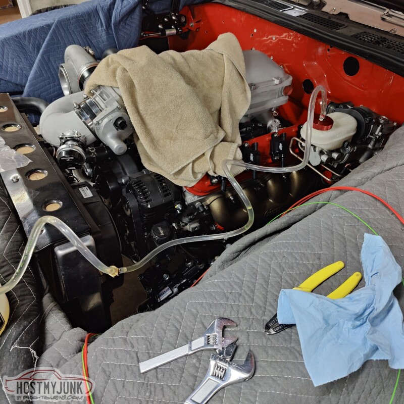
Today's update is a bit random because we kind of jumped around doing various tasks. Since the brake lines were done, I figured it was about time to see if the iBooster actually works ad if we can bled the brakes.
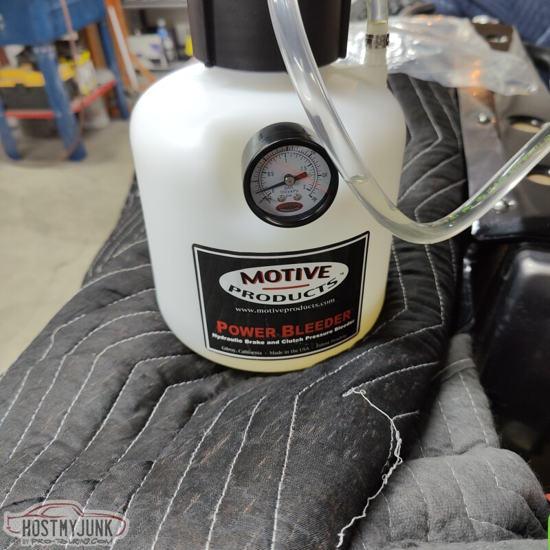
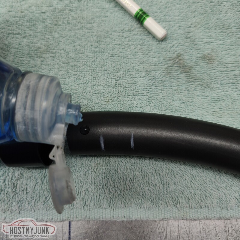
I have heard a lot of good things about the Motive Products brake bleeders, so I thought I would get one to try. I have to say that I will never bleed brakes any other way. The process was super simple and I barely spilled any brake fluid.
I got the version of the Motive brake blender that came with a MC cap that was compatible with the Tesla MC cap. It also works on many newer GM cars.
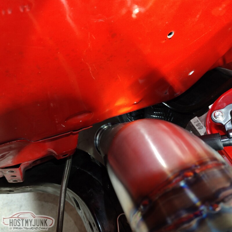
While I wasn't around, Vic changed the angle of the downpipe a little bit to move it a little further from the firewall. There is a little over an inch now.
Yesterday I also finished up the turbo oil drain pipe by welding on an extension that will feed the drain under the turbo hot parts and feed into the oil pan.
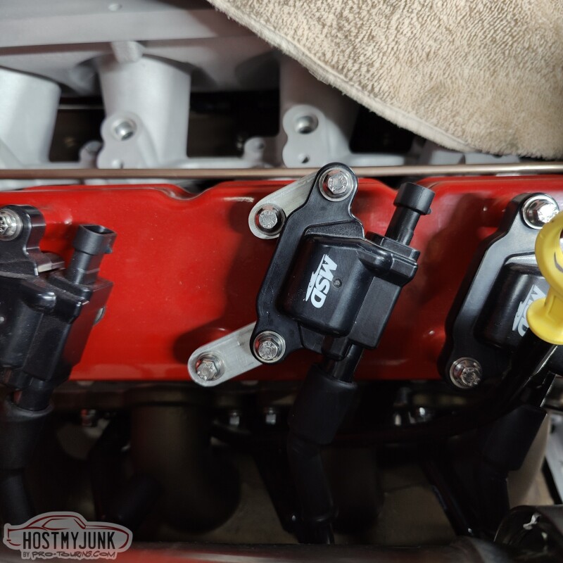
Vic also made these little tabs that position the coils a little higher and over. This was done to move the spark plug wires away from the downpipe.
Andrew
I have heard a lot of good things about the Motive Products brake bleeders, so I thought I would get one to try. I have to say that I will never bleed brakes any other way. The process was super simple and I barely spilled any brake fluid.
I got the version of the Motive brake blender that came with a MC cap that was compatible with the Tesla MC cap. It also works on many newer GM cars.
While I wasn't around, Vic changed the angle of the downpipe a little bit to move it a little further from the firewall. There is a little over an inch now.
Yesterday I also finished up the turbo oil drain pipe by welding on an extension that will feed the drain under the turbo hot parts and feed into the oil pan.
Vic also made these little tabs that position the coils a little higher and over. This was done to move the spark plug wires away from the downpipe.
Andrew
Thread Starter
Joined: Mar 2003
Posts: 10,604
Likes: 1,881
From: Little Austin
Before talking about today's update, I realized that I really didn't mention how the iBooster feels. After bleeding the brakes, we powered up the iBooster and it just started working. The pedal effort is pretty light, but very smooth. Pedal travel is also fairly short before the pedal gets really hard to press. As of now I think the driving experience is going to be greatly improved over the manual brakes that I had before.
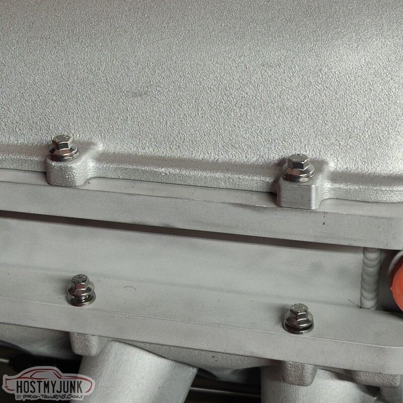
Today's update is also just a random collection of small projects. Last week I ordered all new ARP hardware for the intake lid and the intercooler. The included hardware was adequate, but silver cad plated bolts tend to look like garbage after a very short time. The ARP stainless hardware will look great for a long time.
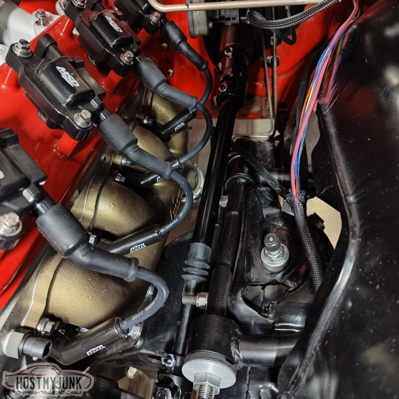
I also finished installing the new, collapsable steering shaft and new u-joints from Borgeson.
I also finished up the oil drain for the turbo. Here is how it wraps around the up-pipe.
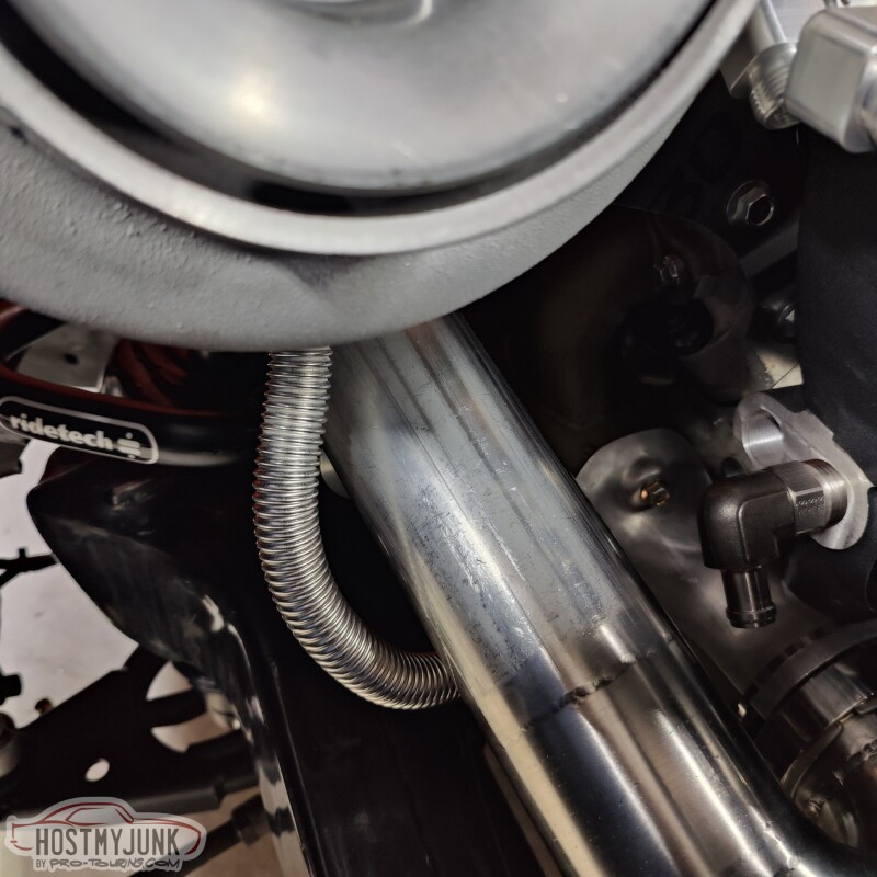
Then it goes under all of the turbo hot pipes, pointing at the fitting in the oil pan.
The only thing left is to put a bead on the 5/8" tube and add a short length of rubber hose between the tube and the oil pan fitting.
Lastly, I have been doing a lot of looking and thinking about where to mount the boost control solenoids. There is quite a bit of plumbing that needs to go between the wastegate, turbo compressor outlet, and the boost solenoids. I want to keep that plumbing as short and simple as possible, so I am thinking about making a bracket and mounting them under the nose of the intake lid.
This location will make the plumbing relatively short and keep the solenoids relatively hidden.
Andrew
Today's update is also just a random collection of small projects. Last week I ordered all new ARP hardware for the intake lid and the intercooler. The included hardware was adequate, but silver cad plated bolts tend to look like garbage after a very short time. The ARP stainless hardware will look great for a long time.
I also finished installing the new, collapsable steering shaft and new u-joints from Borgeson.
I also finished up the oil drain for the turbo. Here is how it wraps around the up-pipe.
Then it goes under all of the turbo hot pipes, pointing at the fitting in the oil pan.
The only thing left is to put a bead on the 5/8" tube and add a short length of rubber hose between the tube and the oil pan fitting.
Lastly, I have been doing a lot of looking and thinking about where to mount the boost control solenoids. There is quite a bit of plumbing that needs to go between the wastegate, turbo compressor outlet, and the boost solenoids. I want to keep that plumbing as short and simple as possible, so I am thinking about making a bracket and mounting them under the nose of the intake lid.
This location will make the plumbing relatively short and keep the solenoids relatively hidden.
Andrew
Thread Starter
Joined: Mar 2003
Posts: 10,604
Likes: 1,881
From: Little Austin
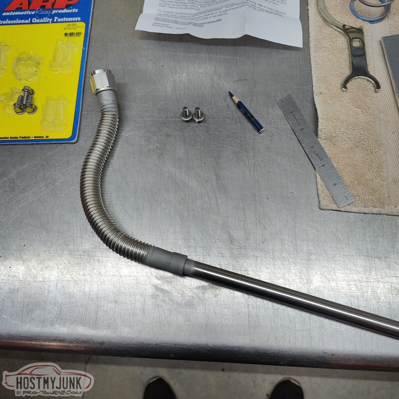
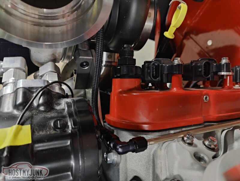
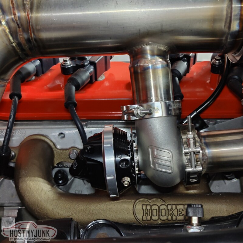
Today I got some PTFE hose and -4AN fittings and made the flex line for the turbo oil feed.
I gave it a nice, soft S-shape to keep it tucked away.
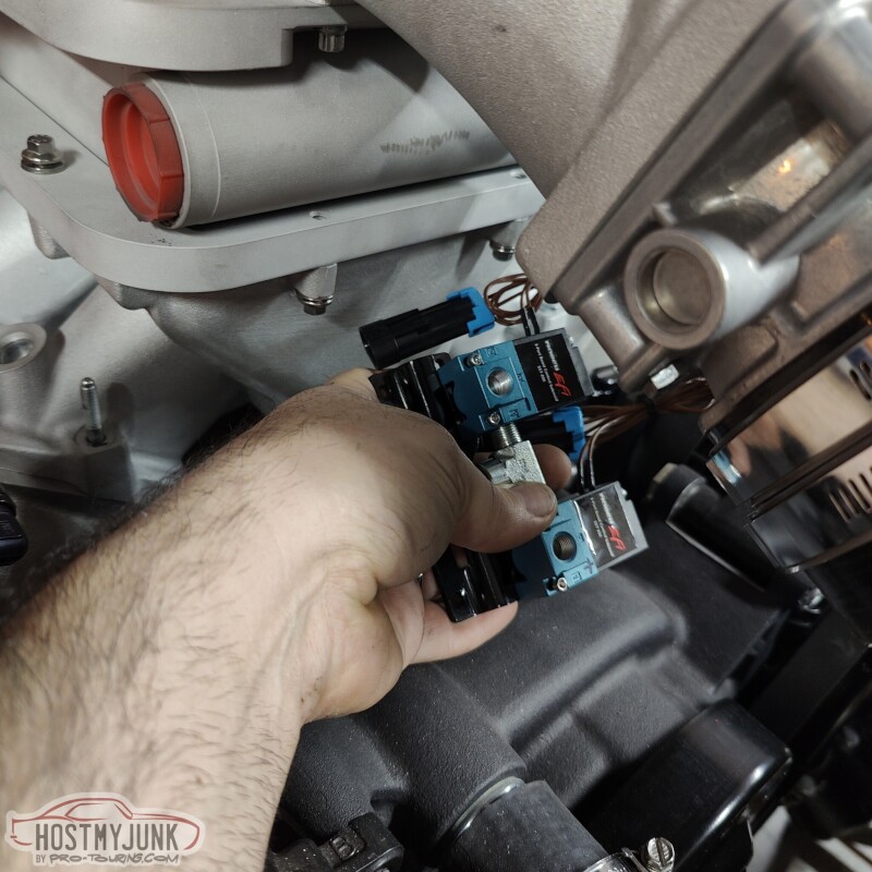
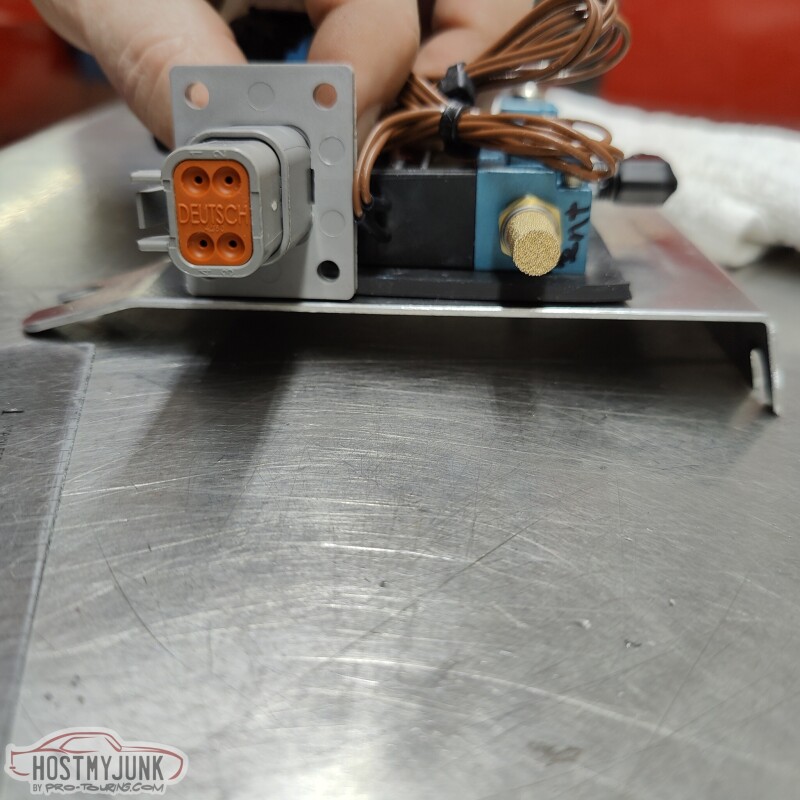
Vic made a little bracket to hold the boost solenoids just under the intake lid snout. The mounting points for the bracket have slots, so the bolts just need to be loosened up to put it on or remove it.
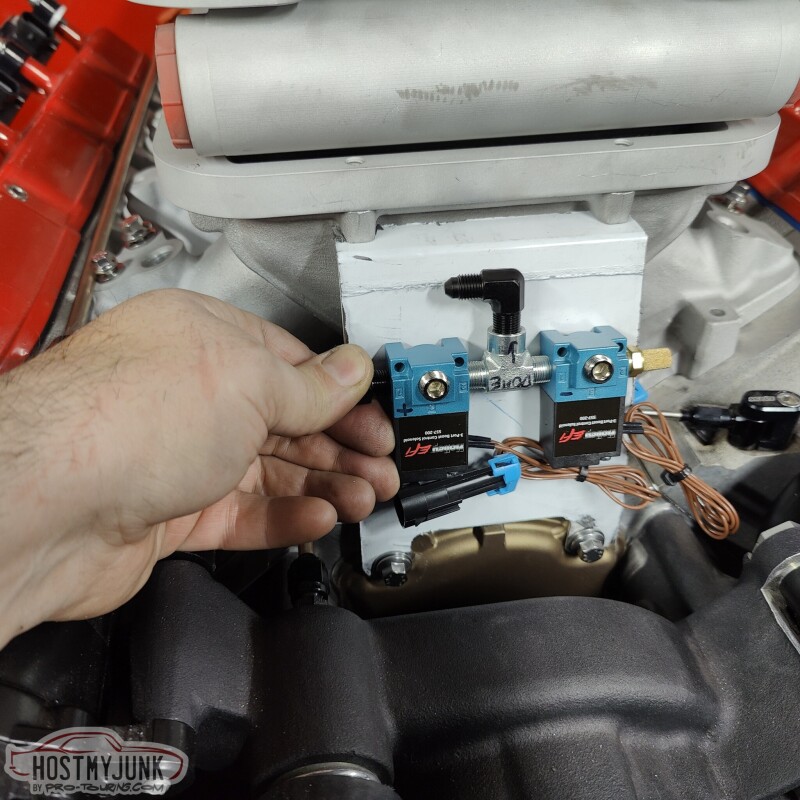
One of the big reasons for choosing this location and orientation is so that the two nipples face the general direction of the wastegate and turbo. One of the lines needs to go to the top of the wastage dome and the other needs to go to the turbo compressor discharge.
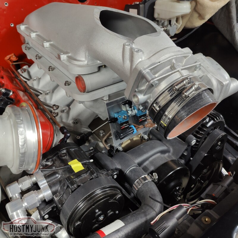
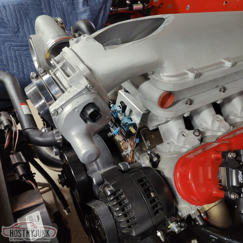
Here is the view from the other side. I am going to have my friend Blake design and print a cover for the solenoids.
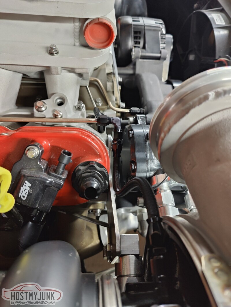
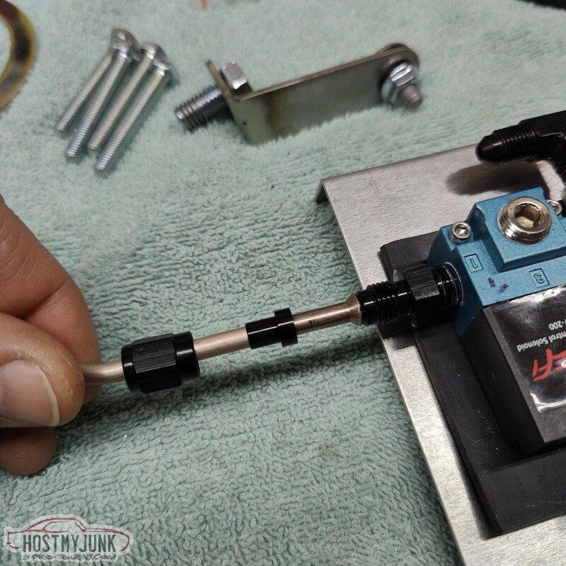
Since the wastegate is not super accessible and is surrounded by hot parts, I decided to plumb everything going to it using NiCopp 3/16" tubing. That way I don't have to worry about melting through the typical nylon hose and push-lock fittings.
This is the line from the compressor discharge to the bottom of the dome.
This TurboSmart wastegate has provisions for water cooling, so once the heater hose fittings are finalized, I will tap them and feet coolant to the dome of the wastegate.
Andrew
I gave it a nice, soft S-shape to keep it tucked away.
Vic made a little bracket to hold the boost solenoids just under the intake lid snout. The mounting points for the bracket have slots, so the bolts just need to be loosened up to put it on or remove it.
One of the big reasons for choosing this location and orientation is so that the two nipples face the general direction of the wastegate and turbo. One of the lines needs to go to the top of the wastage dome and the other needs to go to the turbo compressor discharge.
Here is the view from the other side. I am going to have my friend Blake design and print a cover for the solenoids.
Since the wastegate is not super accessible and is surrounded by hot parts, I decided to plumb everything going to it using NiCopp 3/16" tubing. That way I don't have to worry about melting through the typical nylon hose and push-lock fittings.
This is the line from the compressor discharge to the bottom of the dome.
This TurboSmart wastegate has provisions for water cooling, so once the heater hose fittings are finalized, I will tap them and feet coolant to the dome of the wastegate.
Andrew
TECH Fanatic


Joined: Nov 2014
Posts: 1,301
Likes: 658
Thread Starter
Joined: Mar 2003
Posts: 10,604
Likes: 1,881
From: Little Austin
All of the TurboSmart wastegates have water cooling provisions:
https://www.turbosmart.com/external-wastegates/
Andrew
https://www.turbosmart.com/external-wastegates/
Andrew
Thread Starter
Joined: Mar 2003
Posts: 10,604
Likes: 1,881
From: Little Austin
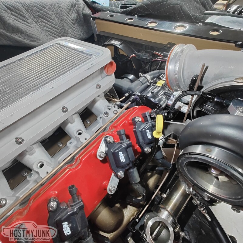
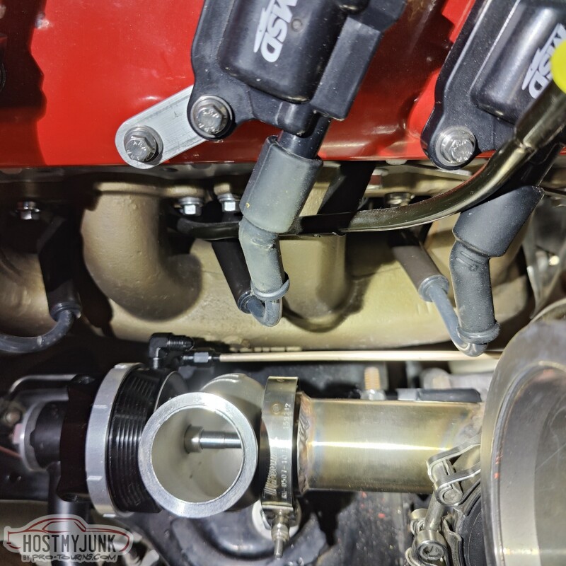
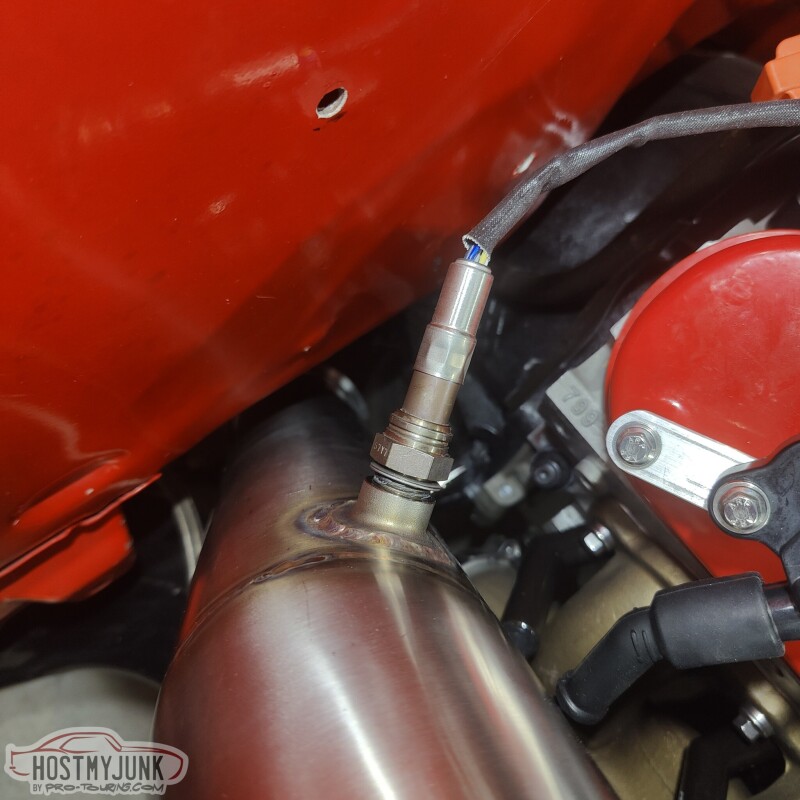
I try to do a little something everyday to keep making progress. We added a bung for the oxygen sensor. I wanted it easily accessible, but also not super visible.
We also added a bung in the charge pipe and I added a small tube to feed boost pressure to the feed side of the boost solenoids.
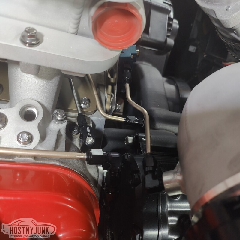
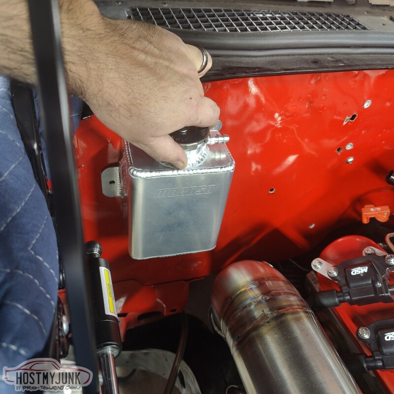
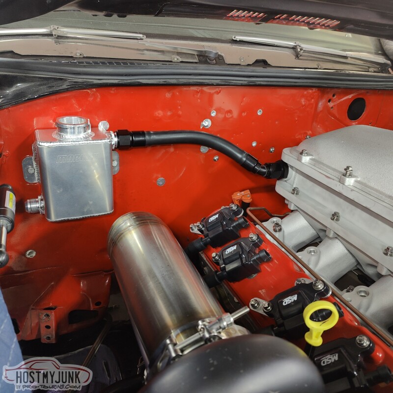
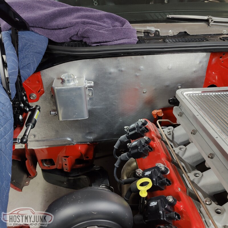
It was also time to think about where the fill tank for the A2W intercooler might go. I am thinking about this location on the firewall. I added a 45 degree fitting to the intercooler just to see how the hoses might be routed.
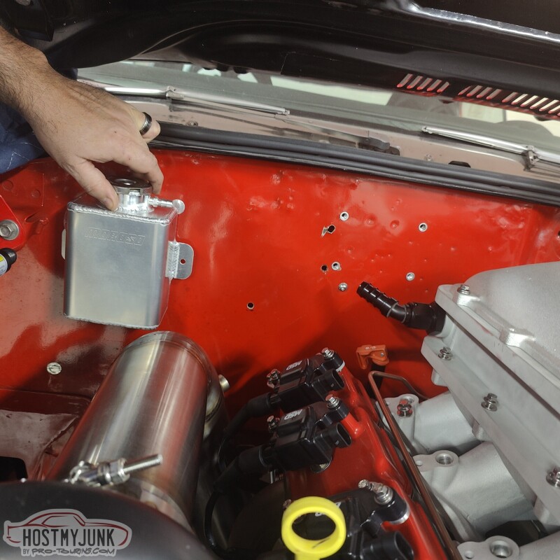
The tank looks like it is close to the downpipe, but there is actually quite a bit of space. The tank also needs to have a fill bung aded to the top of the right side and an outlet on the left side.
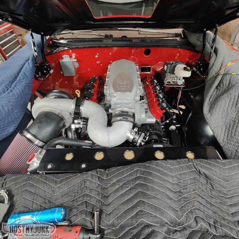
This is just an overall shot of the engine compartment as it sits now.
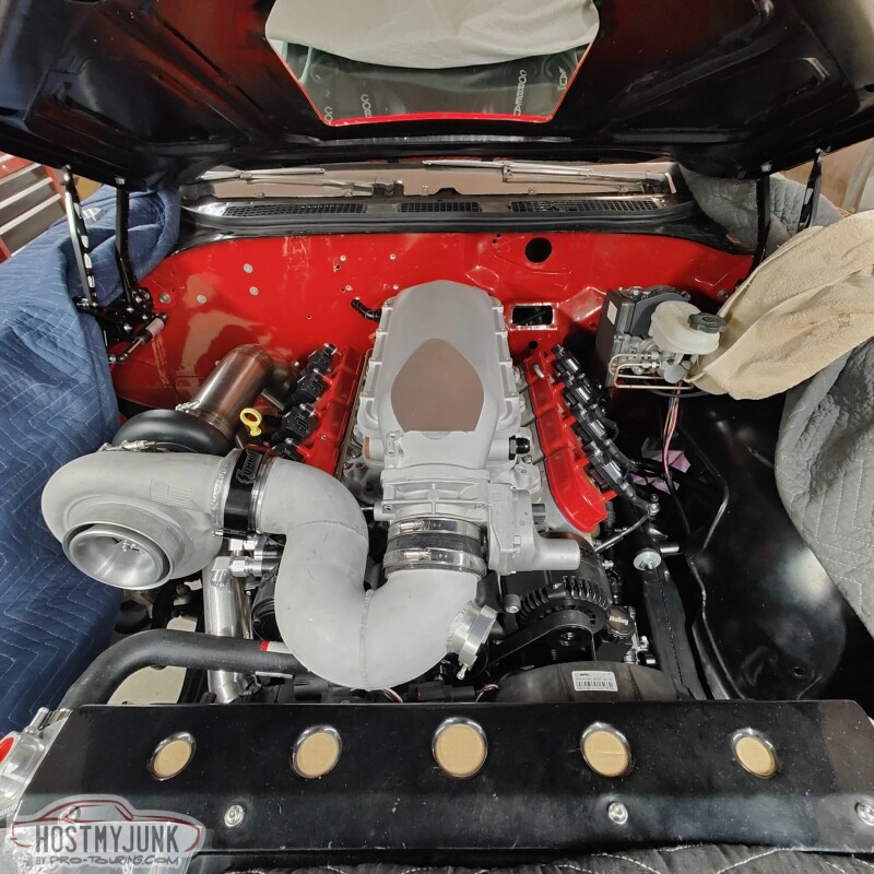
Baby steps...
Andrew
We also added a bung in the charge pipe and I added a small tube to feed boost pressure to the feed side of the boost solenoids.
It was also time to think about where the fill tank for the A2W intercooler might go. I am thinking about this location on the firewall. I added a 45 degree fitting to the intercooler just to see how the hoses might be routed.
The tank looks like it is close to the downpipe, but there is actually quite a bit of space. The tank also needs to have a fill bung aded to the top of the right side and an outlet on the left side.
This is just an overall shot of the engine compartment as it sits now.
Baby steps...
Andrew


Just gotta say I love this thread soo damn much, thanks a ton for the specific GOOD pics and detailed explanations.
Even though I�m fairly young, I really miss when forums where dominant and we got a ton of these great build threads, seems few and far new tween now with social media.
love this project so much and the car and setup is sick af!
Even though I�m fairly young, I really miss when forums where dominant and we got a ton of these great build threads, seems few and far new tween now with social media.
love this project so much and the car and setup is sick af!
Thread Starter
Joined: Mar 2003
Posts: 10,604
Likes: 1,881
From: Little Austin
Just gotta say I love this thread soo damn much, thanks a ton for the specific GOOD pics and detailed explanations.
Even though I�m fairly young, I really miss when forums where dominant and we got a ton of these great build threads, seems few and far new tween now with social media.
love this project so much and the car and setup is sick af!
Even though I�m fairly young, I really miss when forums where dominant and we got a ton of these great build threads, seems few and far new tween now with social media.
love this project so much and the car and setup is sick af!
Come to Kansas City...I'll put you to work...LOL
Andrew
Thread Starter
Joined: Mar 2003
Posts: 10,604
Likes: 1,881
From: Little Austin
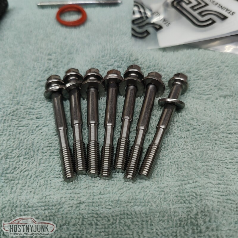
Since I am replacing all of the more visible fasteners on the engine with ARP stainless bolts, I wanted to replace the studs that Holley includes with the Low-Ram intake manifold. I carefully measured the needed length and it looked like ARP already had an intake bolt kit in that length (55mm UHL). Long story short, the ARP bolts didn't have the needed thread length to fully engage into the heads. Vic machined the shank of the bolts so they would torque down against the intake manifold.
I also finished the last bit of NiCopp plumbing for the boost control systems. There is a tube from the turbo compressor to the bottom of the wastegate. There is another tube from the compressor to the fill side of the boost solenoids. Finally, there is a line from the boost solenoids to the top of the wastegate.
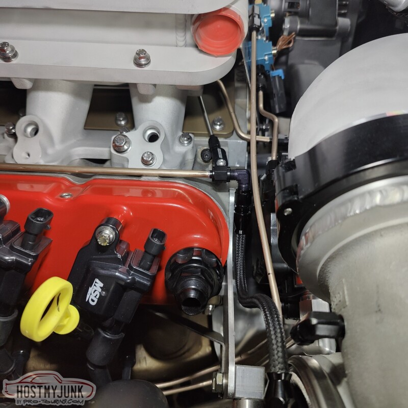
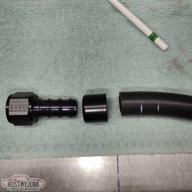
For the intercooler water hoses, I am using the Earl's Super Stock hose and swivel fittings. I have never used these before, but they work awesome. The ferrule spins over the hose to give the hose end a finished look.
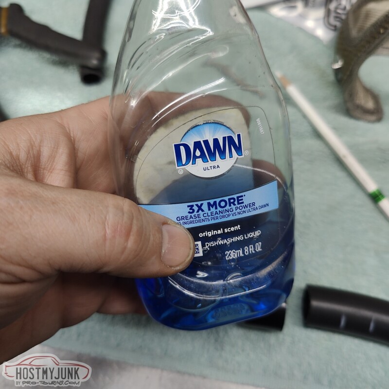
I used dish soap as a lubricant.
Little dab here...
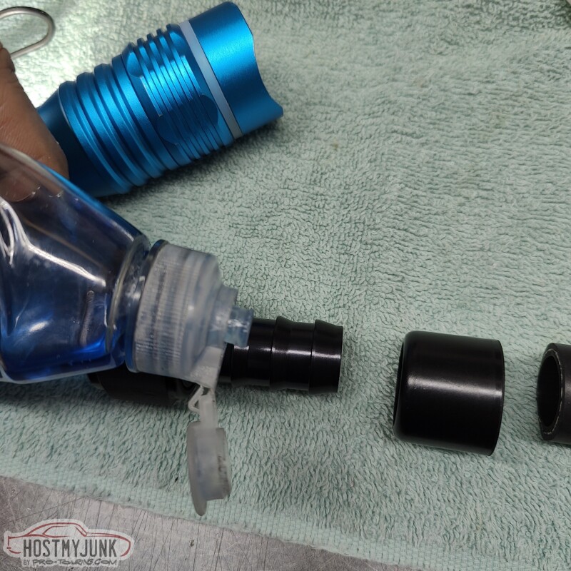
Little dab there...and...
Viola!!!....oh, and Vic had already welded the fittings to the tank and mounted it with rivnuts.
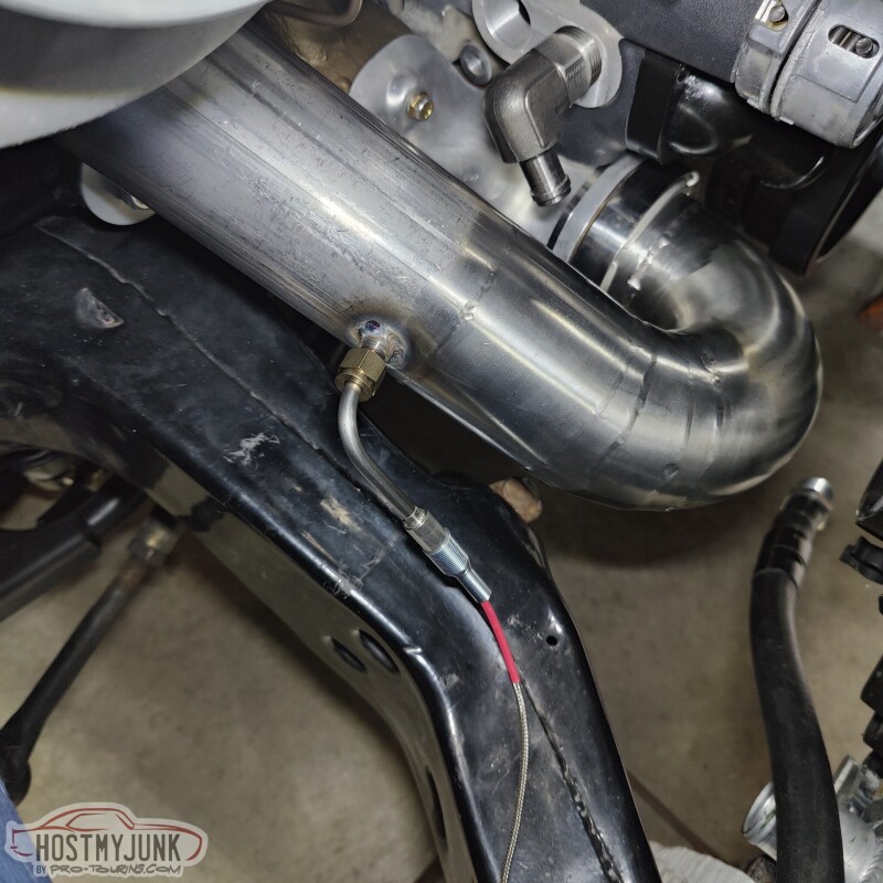
We also added an EGT probe just before the turbine housing.
Andrew
I also finished the last bit of NiCopp plumbing for the boost control systems. There is a tube from the turbo compressor to the bottom of the wastegate. There is another tube from the compressor to the fill side of the boost solenoids. Finally, there is a line from the boost solenoids to the top of the wastegate.
For the intercooler water hoses, I am using the Earl's Super Stock hose and swivel fittings. I have never used these before, but they work awesome. The ferrule spins over the hose to give the hose end a finished look.
I used dish soap as a lubricant.
Little dab here...
Little dab there...and...
Viola!!!....oh, and Vic had already welded the fittings to the tank and mounted it with rivnuts.
We also added an EGT probe just before the turbine housing.
Andrew
Thread Starter
Joined: Mar 2003
Posts: 10,604
Likes: 1,881
From: Little Austin
This morning I received the 1/2" hub centric wheel spacers that I ordered for the rear.
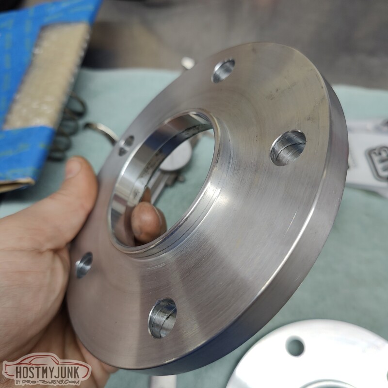
The fit was spot on.
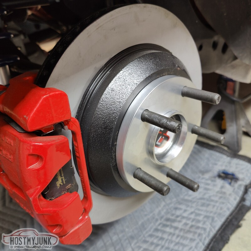
I added this spacer to center the tire in the wheel wells. There is about 1.5" from the tire to the frame on the inside and about 1" on the outside. Also, both sides looked the same, which means the axle is well centered in the chassis and the body is well placed on the frame.
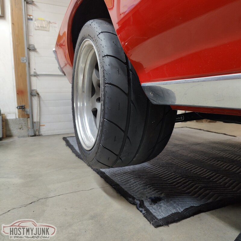
The Mickey Thompson ET Street SS tires look amazing! The rear end is in full droop in this picture. Ride height is still to be determined.
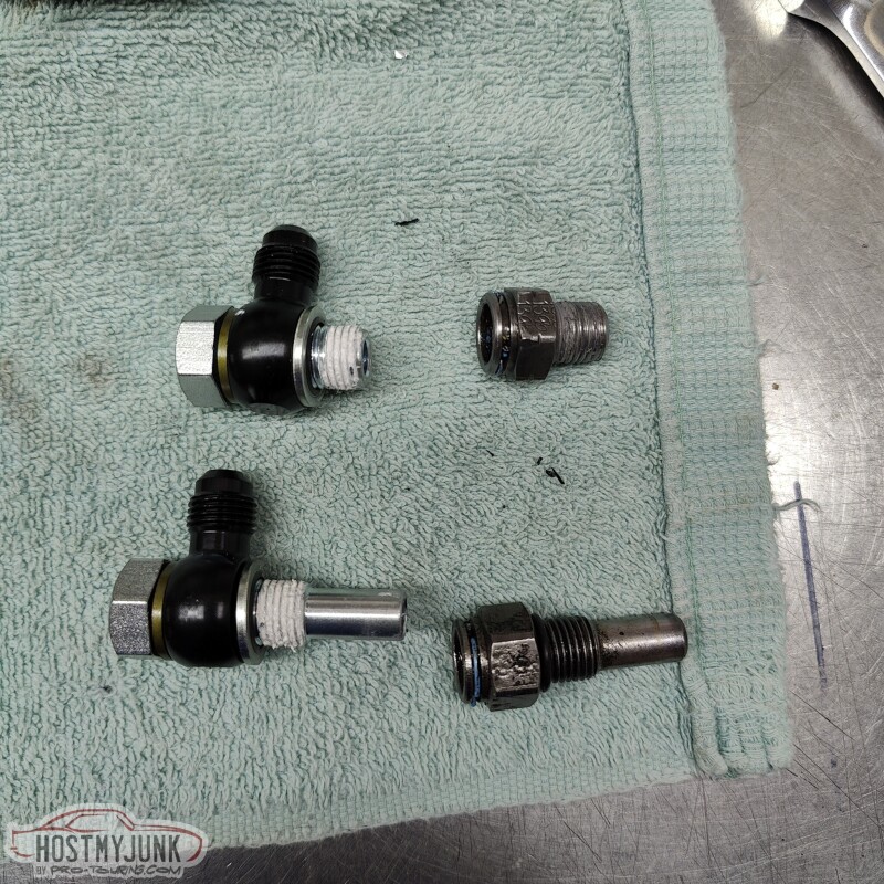
After the fun stuff, it was down to a rather tedious project. These are some banjo -AN adapters for the transmission cooler lines, compared to the stock adapters on the right.
See that hole at the top?
That one...That is where the longer fitting has to go, and there isn't enough room in the transmission tunnel to take the fitting out. So I had to remove the transmission crossmember and lower the trans in order to install these. This picture is with the transmission at full droop.
Here they are installed with the transmission back in place.
Then I got to looking at the intercooler and grabbed a gray scuff pad and started to rub. I really like the brushed look for the intercooler, so I will use the gray scuff pad over all of it and leave it a natural brushed finish (the rest is bead blasted for now).
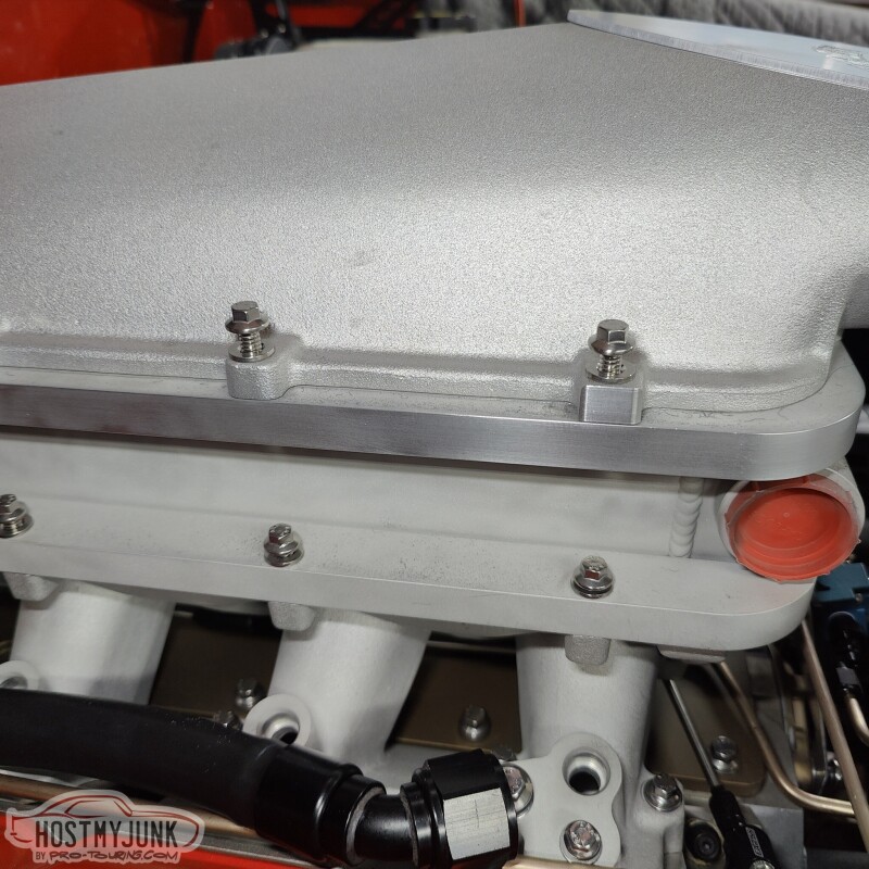
A big "Thank you" to one of my customers, who graciously engraved my logo into the intake manifold plate.
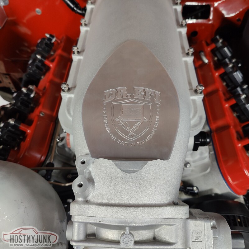
She is starting to look like something!
Andrew
The fit was spot on.
I added this spacer to center the tire in the wheel wells. There is about 1.5" from the tire to the frame on the inside and about 1" on the outside. Also, both sides looked the same, which means the axle is well centered in the chassis and the body is well placed on the frame.
The Mickey Thompson ET Street SS tires look amazing! The rear end is in full droop in this picture. Ride height is still to be determined.
After the fun stuff, it was down to a rather tedious project. These are some banjo -AN adapters for the transmission cooler lines, compared to the stock adapters on the right.
See that hole at the top?
That one...That is where the longer fitting has to go, and there isn't enough room in the transmission tunnel to take the fitting out. So I had to remove the transmission crossmember and lower the trans in order to install these. This picture is with the transmission at full droop.
Here they are installed with the transmission back in place.
Then I got to looking at the intercooler and grabbed a gray scuff pad and started to rub. I really like the brushed look for the intercooler, so I will use the gray scuff pad over all of it and leave it a natural brushed finish (the rest is bead blasted for now).
A big "Thank you" to one of my customers, who graciously engraved my logo into the intake manifold plate.
She is starting to look like something!
Andrew
Thread Starter
Joined: Mar 2003
Posts: 10,604
Likes: 1,881
From: Little Austin
Thread Starter
Joined: Mar 2003
Posts: 10,604
Likes: 1,881
From: Little Austin
 The engraved plate is a very nice touch. Always great to have talented friends. I think the egt is something that people should have way more often. AFR is only part of the info that is needed to have the engine safe and happy.
 This morning I received this 4 cavity Deutsch bulkhead connector from Prowireusa. They are one of my Go-to vendors for wiring products.
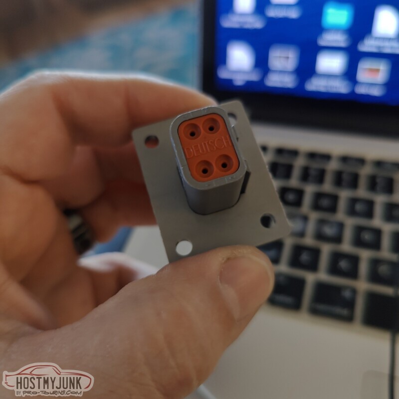
The idea behind getting this connector is that I would be able to wire the boost control solenoids to this connector and have a neat way of connecting them to the rest of the engine harness.
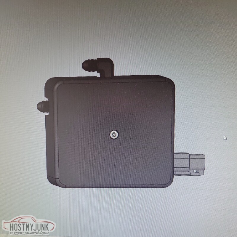
My friend Blake designed this little cover for the boost solenoids and it will hold the bulkhead connector in place and also give the solenoids a much cleaner look. He is also going to 3D print the cover.
Vic also added an elbow to the end of the downpipe with a v-band. The rest of the exhaust system will be built from here back.
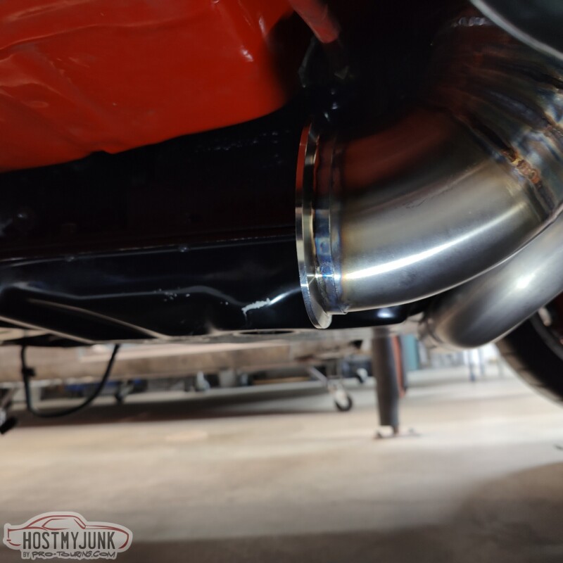
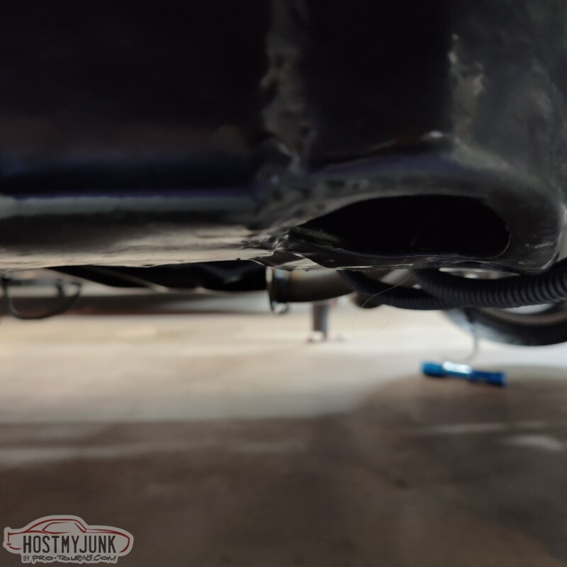
This is a terrible picture, but I was just trying to show that the downpipe doesn't hang very low. In fact, the crossover pipe from the driver's exhaust manifold is the lowest point under the car.
Vic also made some adjustments to the short pipe that goes from the wastegate into the downpipe. It was about 3/32" too short which made it difficult to install the v-band. Vic cut that pipe, sleeved it, and welded it all back together.
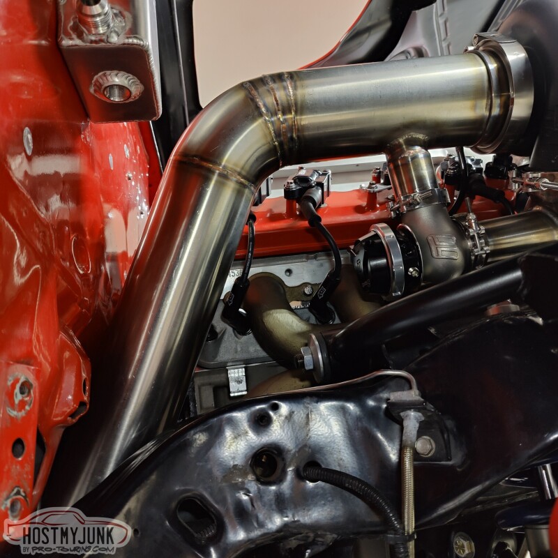
You can better see the sleeve here.
He also added a small tab to keep the downpipe more stable.
Tomorrow is a big day and I can't wait to share what we have planned.
Andrew

Nice work.
How does that Nicopp work, do you have to flare the ends or something? Is it easily bendable and/or do you use a tubing bender?
Thanks,
John a member of the nyloc hose club
How does that Nicopp work, do you have to flare the ends or something? Is it easily bendable and/or do you use a tubing bender?
Thanks,
John a member of the nyloc hose club
Thread Starter
Joined: Mar 2003
Posts: 10,604
Likes: 1,881
From: Little Austin
The NiCopp can be bent easily (sometimes too easily) by hand and comes in 25' rolls. For best results I use a tuning straightener and the mini Earl's tubing bender.
Andrew
Last edited by Project GatTagO; Jan 26, 2023 at 05:30 PM.
Thread Starter
Joined: Mar 2003
Posts: 10,604
Likes: 1,881
From: Little Austin
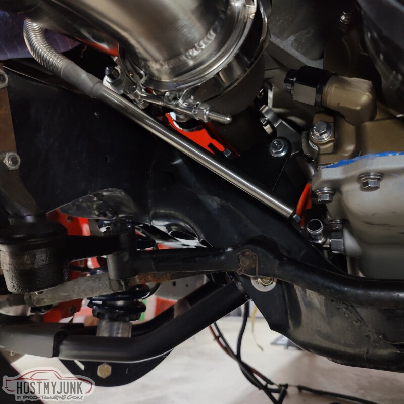
Progress is being made. Yesterday I sent off the up-pipe and the downpipe to HeaderShield to have them wrapped. Today I showed up at Vic's and saw that he had installed the firewall shield that we had been discussing. We will probably take the intake off and go all the way across as much as we can with it.
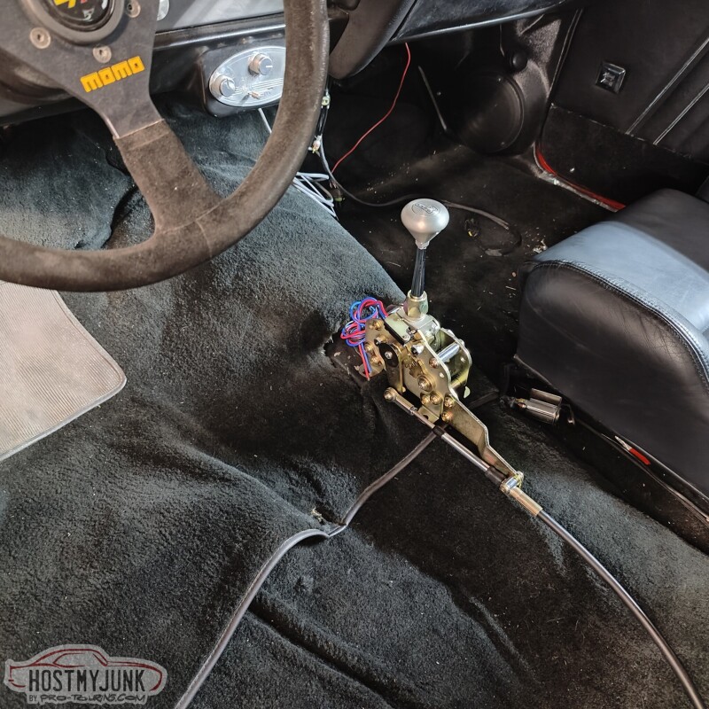
I also pulled the drive's side seat to start mocking up the shifter. What you don't see is that under the carpet I had removed the shifter hump that was installed 20 years ago to make room for the Richmond 6 speed shifter. With that hump gone (it was bolted in) the console that I plan to use actually sort of fits. I ordered a partial left side front floor patch panel that includes part of the transmission tunnel. We are going to use that to close off the hole and have the shape of the floor be how it was with an auto trans. Then the 70 Chevelle console that I got should fit a lot better.
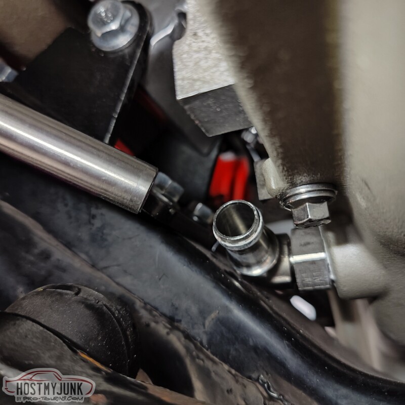
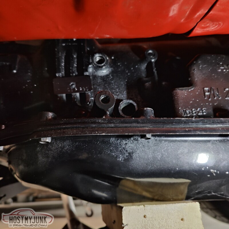
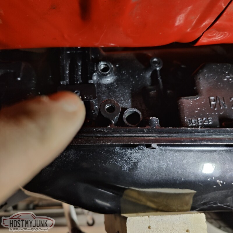
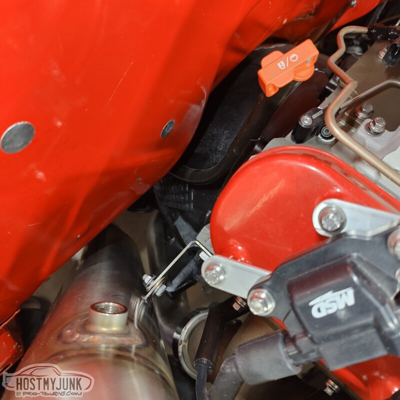
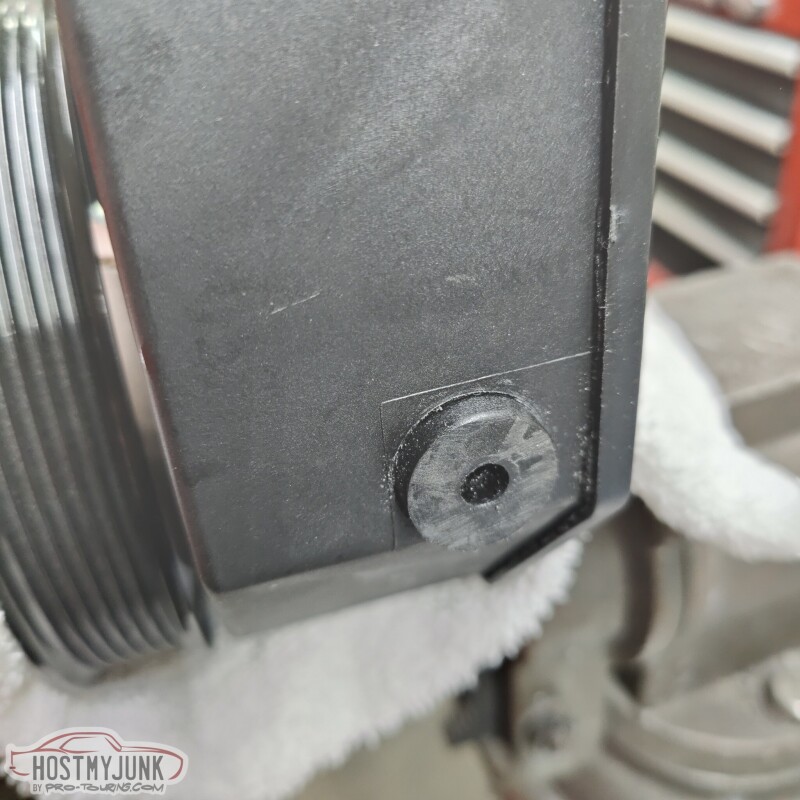
In order to do the power steering plumbing, this little nipple for the fluid return had to be cut off because it was pointing right at the steering box.
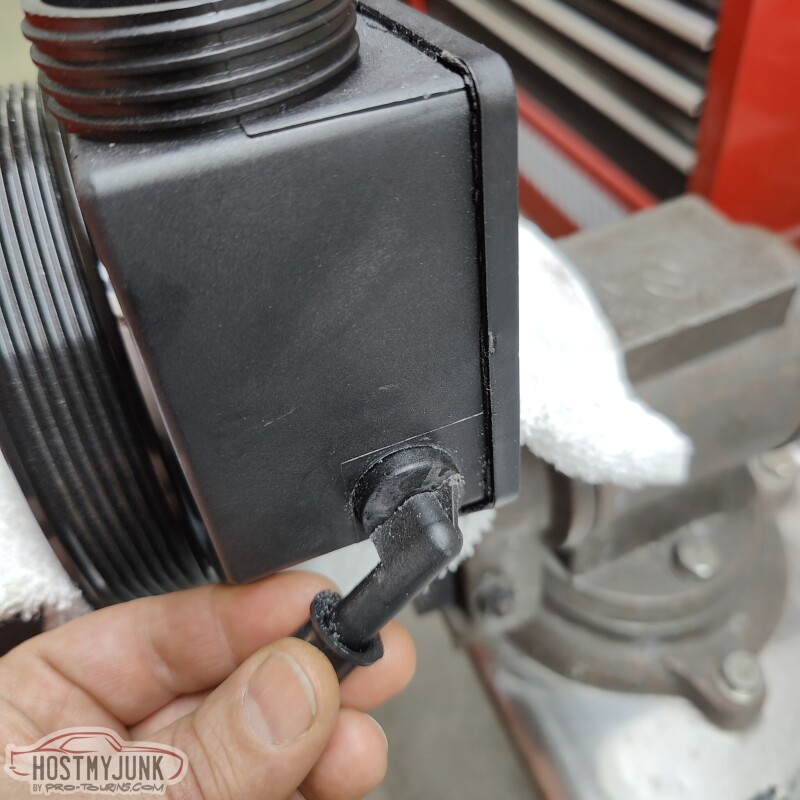
The hole is quite small, so we are going to install a 1/8" NPT to AN-6 fitting there.
Andrew
I also pulled the drive's side seat to start mocking up the shifter. What you don't see is that under the carpet I had removed the shifter hump that was installed 20 years ago to make room for the Richmond 6 speed shifter. With that hump gone (it was bolted in) the console that I plan to use actually sort of fits. I ordered a partial left side front floor patch panel that includes part of the transmission tunnel. We are going to use that to close off the hole and have the shape of the floor be how it was with an auto trans. Then the 70 Chevelle console that I got should fit a lot better.
In order to do the power steering plumbing, this little nipple for the fluid return had to be cut off because it was pointing right at the steering box.
The hole is quite small, so we are going to install a 1/8" NPT to AN-6 fitting there.
Andrew
Thread Starter
Joined: Mar 2003
Posts: 10,604
Likes: 1,881
From: Little Austin
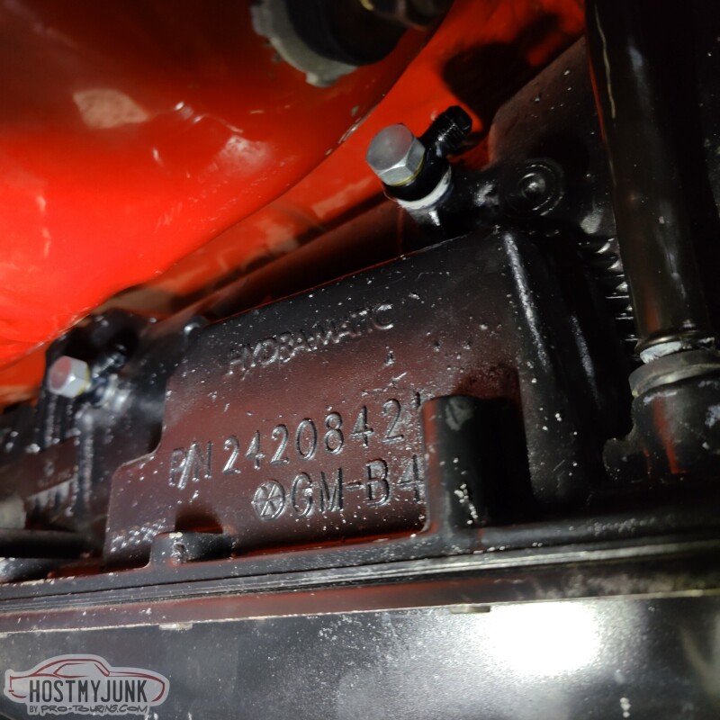
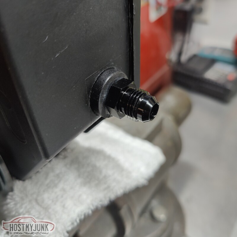
A quick trip to Star Performance produced the 1/8" NPT to AN-6 Male fitting, and the power steering return is now sorted.
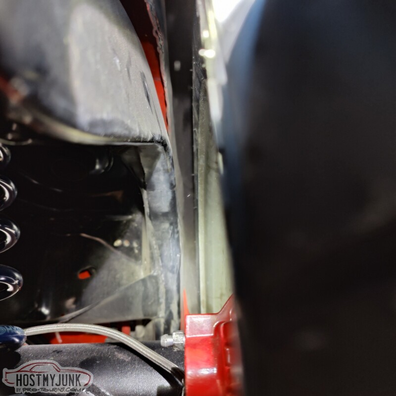
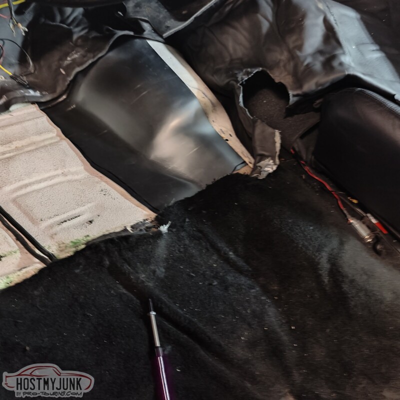
The next project to tackle was this hole in the side of the transmission tunnel.
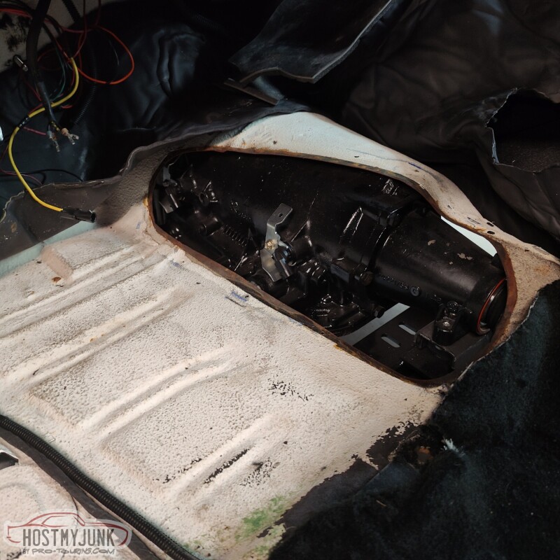
The hole used to have a cover that had a shifter hump in it to clear the shifter and linkage for the Richmond 6 speed that used to be in the car. With that transmission gone and the 4L80e in its place, a new cover needed to be made.
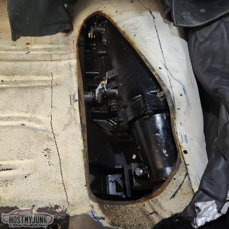
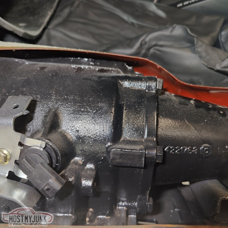
Here you can see how close the transmission is to the trans tunnel. My body bushings are 20 years old. They are not cracked, but I am sure they have settled some, which is contributing to the lack of clearance.
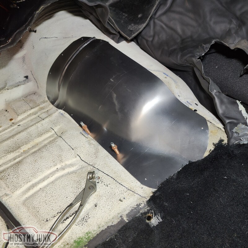
A quick Google search showed that partial floor pan patch panels were readily available. I called The Parts Place and they had one in stock and had it at my door in two days. You can see that part of the panel includes the needed piece to start making a new cover for the tunnel.
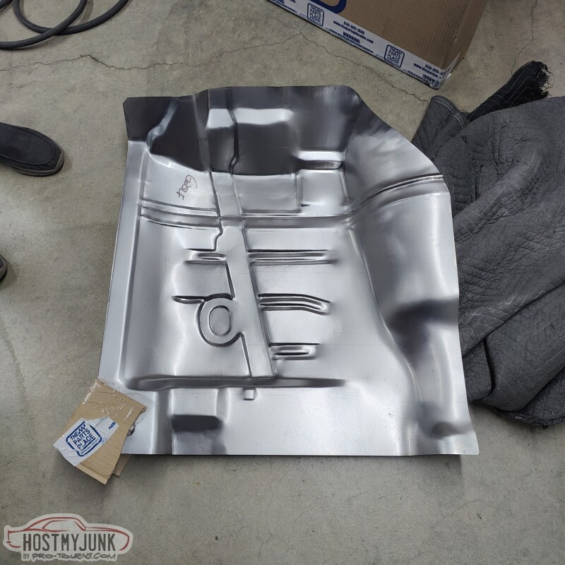
I trimmed it big to start...
Then trimmed it to the final shape...
and started to drill the necessary mounting holes.
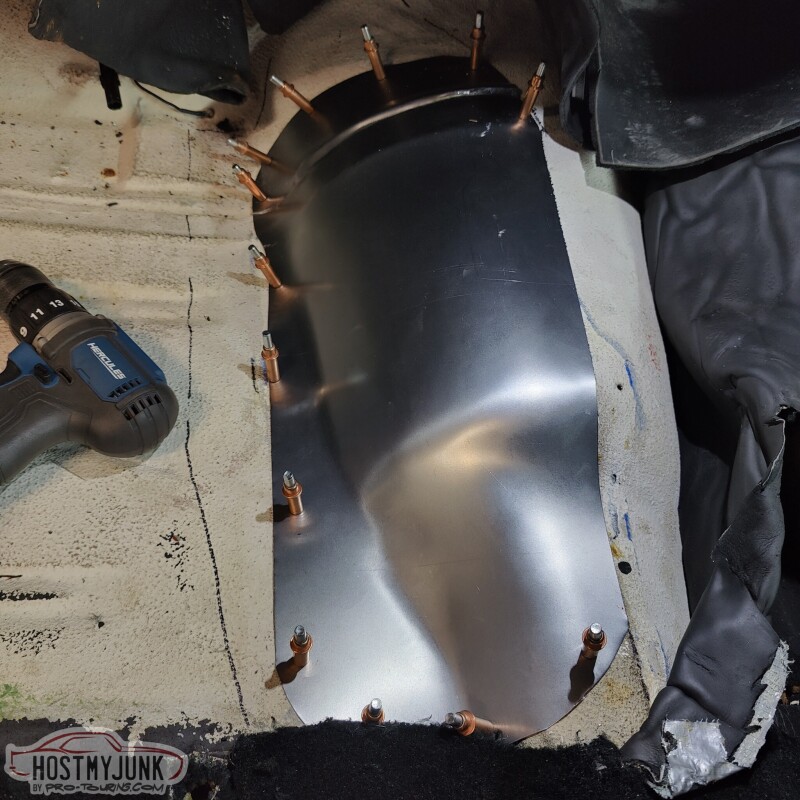
Turned out pretty good in the end, without having to do any custom metal shaping, which I don't have the skills to do anyway....
Andrew
The next project to tackle was this hole in the side of the transmission tunnel.
The hole used to have a cover that had a shifter hump in it to clear the shifter and linkage for the Richmond 6 speed that used to be in the car. With that transmission gone and the 4L80e in its place, a new cover needed to be made.
Here you can see how close the transmission is to the trans tunnel. My body bushings are 20 years old. They are not cracked, but I am sure they have settled some, which is contributing to the lack of clearance.
A quick Google search showed that partial floor pan patch panels were readily available. I called The Parts Place and they had one in stock and had it at my door in two days. You can see that part of the panel includes the needed piece to start making a new cover for the tunnel.
I trimmed it big to start...
Then trimmed it to the final shape...
and started to drill the necessary mounting holes.
Turned out pretty good in the end, without having to do any custom metal shaping, which I don't have the skills to do anyway....
Andrew

TECH Apprentice

Joined: Apr 2019
Posts: 301
Likes: 129
Progress is being made. Yesterday I sent off the up-pipe and the downpipe to HeaderShield to have them wrapped. Today I showed up at Vic's and saw that he had installed the firewall shield that we had been discussing. We will probably take the intake off and go all the way across as much as we can with it.
I also pulled the drive's side seat to start mocking up the shifter. What you don't see is that under the carpet I had removed the shifter hump that was installed 20 years ago to make room for the Richmond 6 speed shifter. With that hump gone (it was bolted in) the console that I plan to use actually sort of fits. I ordered a partial left side front floor patch panel that includes part of the transmission tunnel. We are going to use that to close off the hole and have the shape of the floor be how it was with an auto trans. Then the 70 Chevelle console that I got should fit a lot better.
In order to do the power steering plumbing, this little nipple for the fluid return had to be cut off because it was pointing right at the steering box.
The hole is quite small, so we are going to install a 1/8" NPT to AN-6 fitting there.
Andrew
I am still out in the air about whether or not I want to go turbo or turbo. That intake keeps me thinking turbo since that is partially the reason I want to go blower(not dealing with intercooler issues).
Thread Starter
Joined: Mar 2003
Posts: 10,604
Likes: 1,881
From: Little Austin
It is a self adhesive, reflective sheet that I got from @Summitracing but I don't recall the brand. I think it was made by Heat Shield Products. I looked through my order history but I must have gotten it a while ago as it is no longer available on my Summit account.
Andrew
Andrew
TECH Apprentice
Joined: Apr 2019
Posts: 301
Likes: 129
It is a self adhesive, reflective sheet that I got from @Summitracing but I don't recall the brand. I think it was made by Heat Shield Products. I looked through my order history but I must have gotten it a while ago as it is no longer available on my Summit account.
Andrew
Andrew
Can't wait to see more progress. Been following this a while, definitely awesome!