
First turbo build, 70 GTO...


I just vent to air, I like the WG to kind of be in line with the exhaust flow, why I place it where I do. I will have the car back on the lift today, tired of laying on my old back, lol. I want to ck my cold start anyway. I will see if possible, the WG exhaust could route under the frame to the downpipe. Im not gonna do it, but just see If it was an option.
I saw a Holley 300-245 on Market Place for sale, not sure if the same as yours, but just in case.
I saw a Holley 300-245 on Market Place for sale, not sure if the same as yours, but just in case.

HUH? What stinkies? The only time exhaust should be coming out that pipe is when you've reached max boost, at which point the car should be accelerating rapidly. If you're having stinkies in the car otherwise, then the WG is not fully closing. You might want to do it for noise, but then again, at max boost the exhaust is not exactly quiet.


On The Tree

Joined: Jul 2013
Posts: 193
Likes: 54
mine is dumped next to the manifold in the engine bay right now and it�s extremely loud. You know exactly when it opens. I have a fairly quiet exhaust though as well 4� with a diesel muffler. It�s definitely on my list to recirculate it to the down pipe this winter.
This is my 5th turbo car, and I have never really noticed the noise, prob more from the blowoff valve when you lift off the gas, mainly because it's in the engine comp. Now that I have it on the lift, looks like you could come off the WG, go under the lower control arm pivot area, then into the down pipe. Put a V band on each end.
Thread Starter
Joined: Mar 2003
Posts: 10,604
Likes: 1,881
From: Little Austin
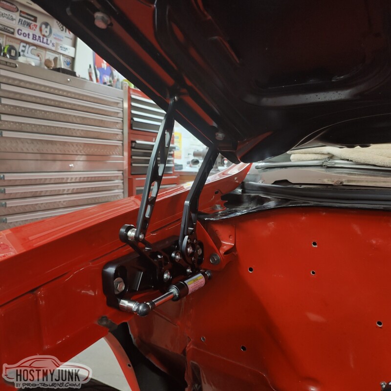
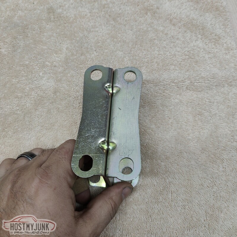
Before we finalized the intake, we thought it would be good to install the new Ring Brothers hinges. These are very well made and have plenty of adjustment to get the hood lined up well.
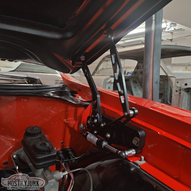
Installing them was a simple remove and replace operation and after a bit of fiddling with the adjustment, the hood was closing better than it ever has before. We did notice that these hinges don't allow the hood to open as much as the stock hinges. I guess this was mentioned on the Ring Brothers website, but I somehow missed it. I really don't think it will cause any issues...
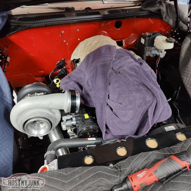
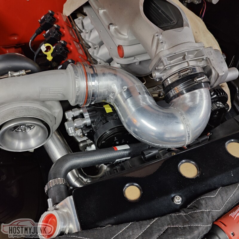
Now that the intake was finalized it was time to keep working on the charge pipe from the compressor outlet to the throttle body.
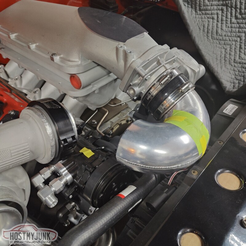
We ended up cutting the 180 degree bend that we had made previously so that half of it could be clocked independently.
This gave us a more clear path to the compressor, so all that is left is to add another 90 and a couple of small straight cuts to make it all fit.
It is a bit of a tortured path, but this is why we chose to stay with 4" piping to keep the pressure drop to a minimum. It is really no more elaborate than if there was an A2A intercooler in the front and we had to make all the associated pieces to work with that. I think this looks super clean too.
Happy New Year to Everyone and thanks for following along.
Andrew
Installing them was a simple remove and replace operation and after a bit of fiddling with the adjustment, the hood was closing better than it ever has before. We did notice that these hinges don't allow the hood to open as much as the stock hinges. I guess this was mentioned on the Ring Brothers website, but I somehow missed it. I really don't think it will cause any issues...
Now that the intake was finalized it was time to keep working on the charge pipe from the compressor outlet to the throttle body.
We ended up cutting the 180 degree bend that we had made previously so that half of it could be clocked independently.
This gave us a more clear path to the compressor, so all that is left is to add another 90 and a couple of small straight cuts to make it all fit.
It is a bit of a tortured path, but this is why we chose to stay with 4" piping to keep the pressure drop to a minimum. It is really no more elaborate than if there was an A2A intercooler in the front and we had to make all the associated pieces to work with that. I think this looks super clean too.
Happy New Year to Everyone and thanks for following along.
Andrew

This is the intake tube that I have:
https://www.intakehoses.com/rubber-e...gree-1639.html
I'm not sure what you're asking in the second part.
Andrew
https://www.intakehoses.com/rubber-e...gree-1639.html
I'm not sure what you're asking in the second part.
Andrew
Thanks for posting that link, just saved me hours of fabing one up.
Thread Starter
Joined: Mar 2003
Posts: 10,604
Likes: 1,881
From: Little Austin
Today we decided to take a little break from turbo stuff and figure out how to upgrade the brakes. Over the last year or so I have been seeing electronically assisted brakes on various cars and on a couple of YouTube channels that I watch. The technology seems really cool and by all accounts they work great.
I started by removing the manual MC and the old mount for the clutch MC. There is a little rust here and there, but remember, this car was "done" 20 years ago. That area will definitely get cleaned up.
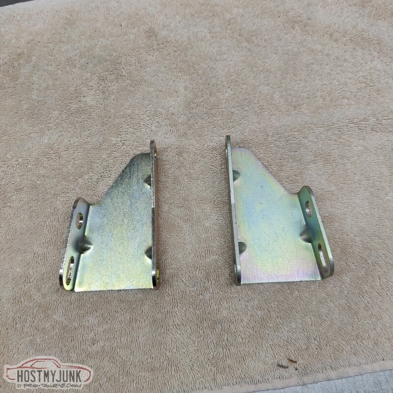
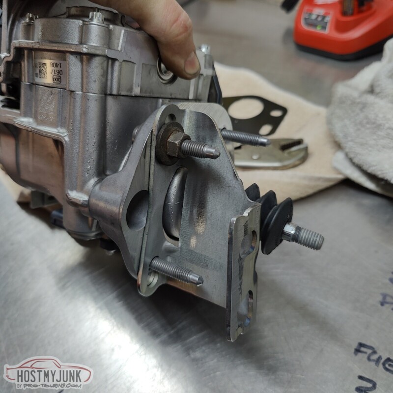
I figured a good place to start to be these brackets that I got them I was planning on doing vacuum power brakes. These are from DSE and it is their reduced angle bracket.
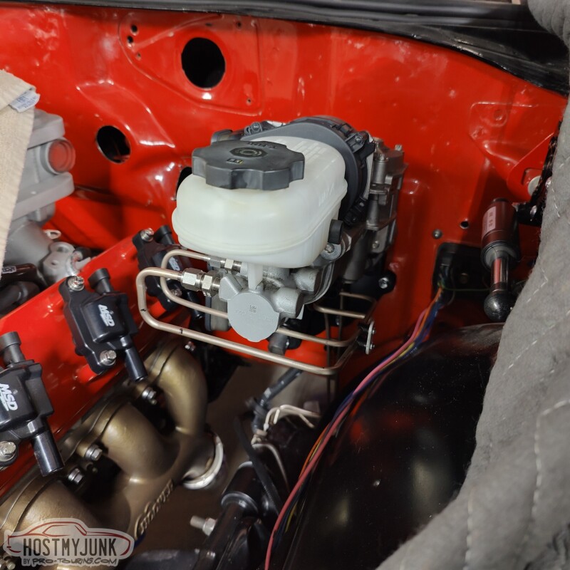
The is the Gen 1 Bosch iBooster unit that I got. It is from a 2010ish Tesla Model S with the adaptive cruise control. Bosch has a Gen 2 model of the iBooster available, but I don't like the looks of them and I am sure that none of the features of the new unit are even applicable to what we are doing here.
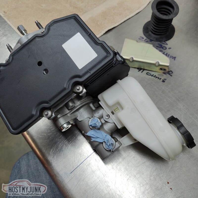
After a little welding, milling and hole sawing, we had the bracket modified to fit the iBooster.
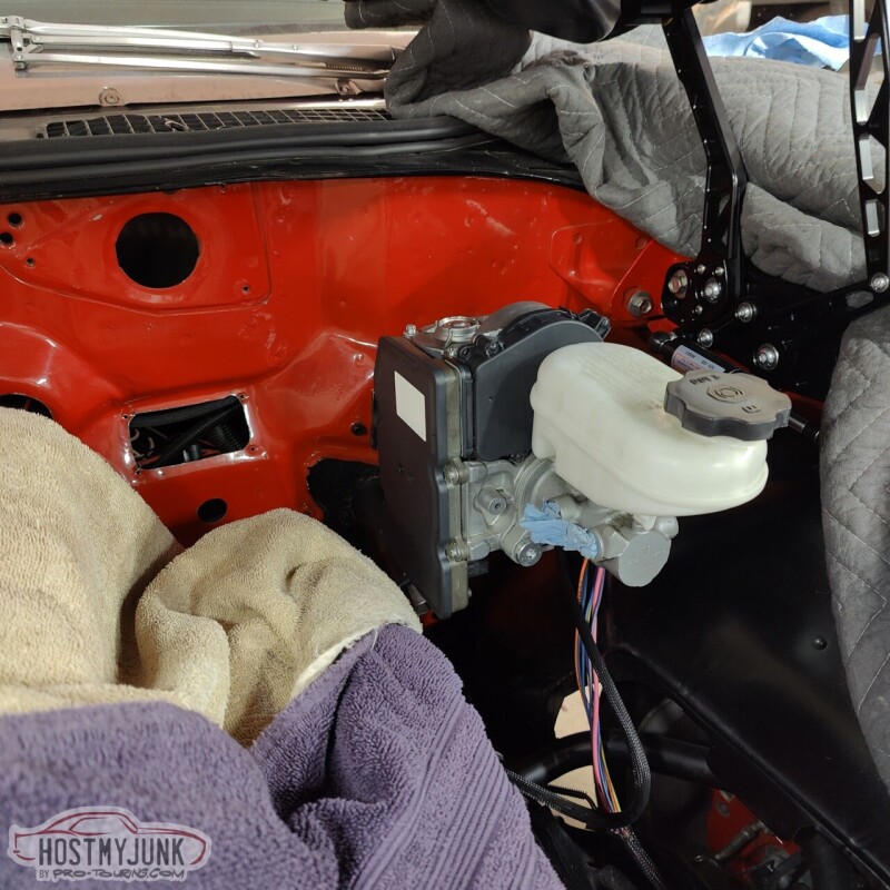
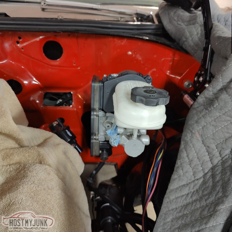
It is bolted to the firewall here, but there is still a lot to sort out.
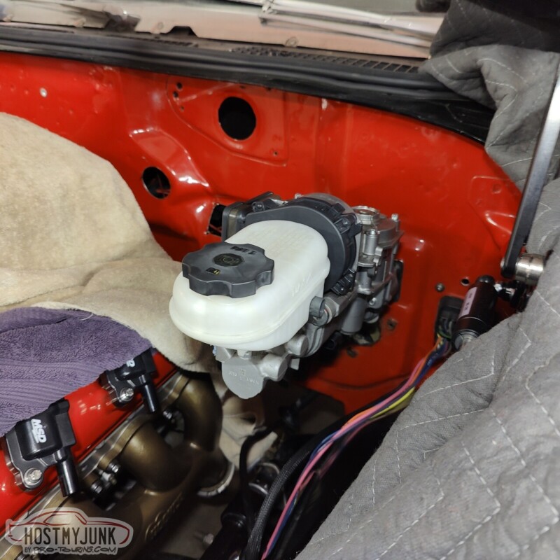
I am not really happy with how the pushrod alignment is looking at the moment. The unit might actually need to be tilted up at the front a little more, but I am already concerned about hood clearance. We will sort out the details the next time.
I really like the way these look. They add a little high-tech touch to the engine compartment.
Andrew
I started by removing the manual MC and the old mount for the clutch MC. There is a little rust here and there, but remember, this car was "done" 20 years ago. That area will definitely get cleaned up.
I figured a good place to start to be these brackets that I got them I was planning on doing vacuum power brakes. These are from DSE and it is their reduced angle bracket.
The is the Gen 1 Bosch iBooster unit that I got. It is from a 2010ish Tesla Model S with the adaptive cruise control. Bosch has a Gen 2 model of the iBooster available, but I don't like the looks of them and I am sure that none of the features of the new unit are even applicable to what we are doing here.
After a little welding, milling and hole sawing, we had the bracket modified to fit the iBooster.
It is bolted to the firewall here, but there is still a lot to sort out.
I am not really happy with how the pushrod alignment is looking at the moment. The unit might actually need to be tilted up at the front a little more, but I am already concerned about hood clearance. We will sort out the details the next time.
I really like the way these look. They add a little high-tech touch to the engine compartment.
Andrew
Thread Starter
Joined: Mar 2003
Posts: 10,604
Likes: 1,881
From: Little Austin
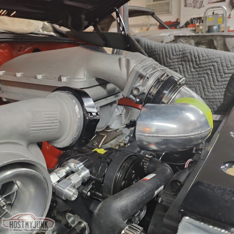
This seems like a pretty straightforward part to make, but it's quite intricate. There is very little space and we had to use a donut to get the radii tight enough to connect the dots.
There is a slight gap where the pipe meets the compressor discharge. This was done to accommodate any movement due to heat, etc...The Summit Racing clamp is made to account for this movement. All that is left is to finish a couple of welds, add the blow-off valve, which will go on the outside bend just before the throttle body, and smooth out whichever welds we can.
Andrew

Thread Starter
Joined: Mar 2003
Posts: 10,604
Likes: 1,881
From: Little Austin
Thanks John!
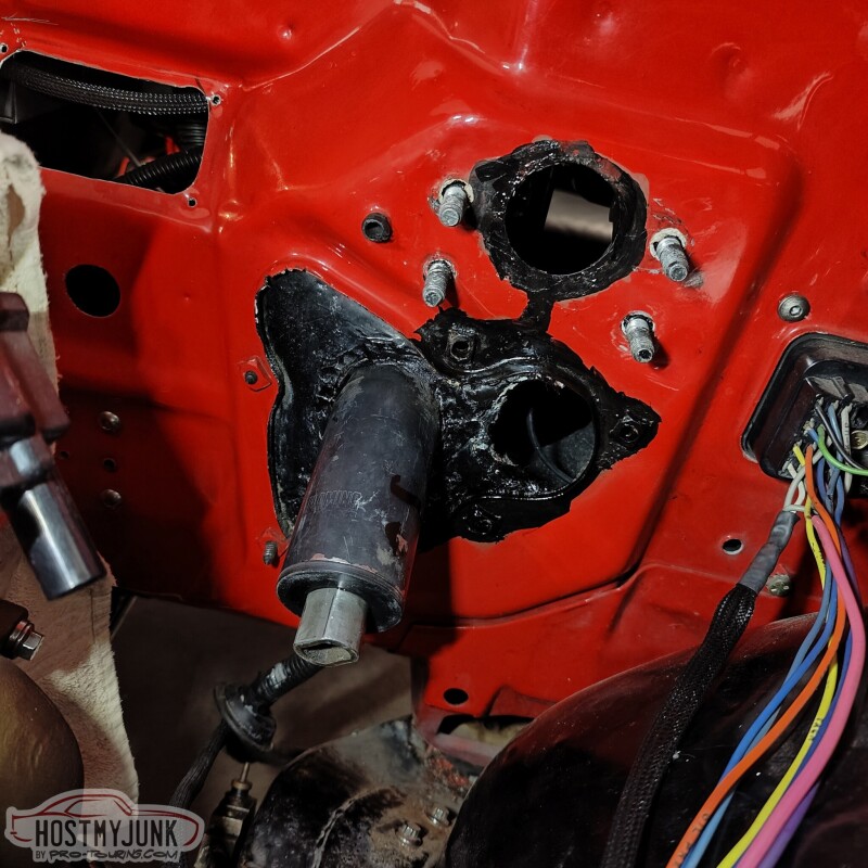
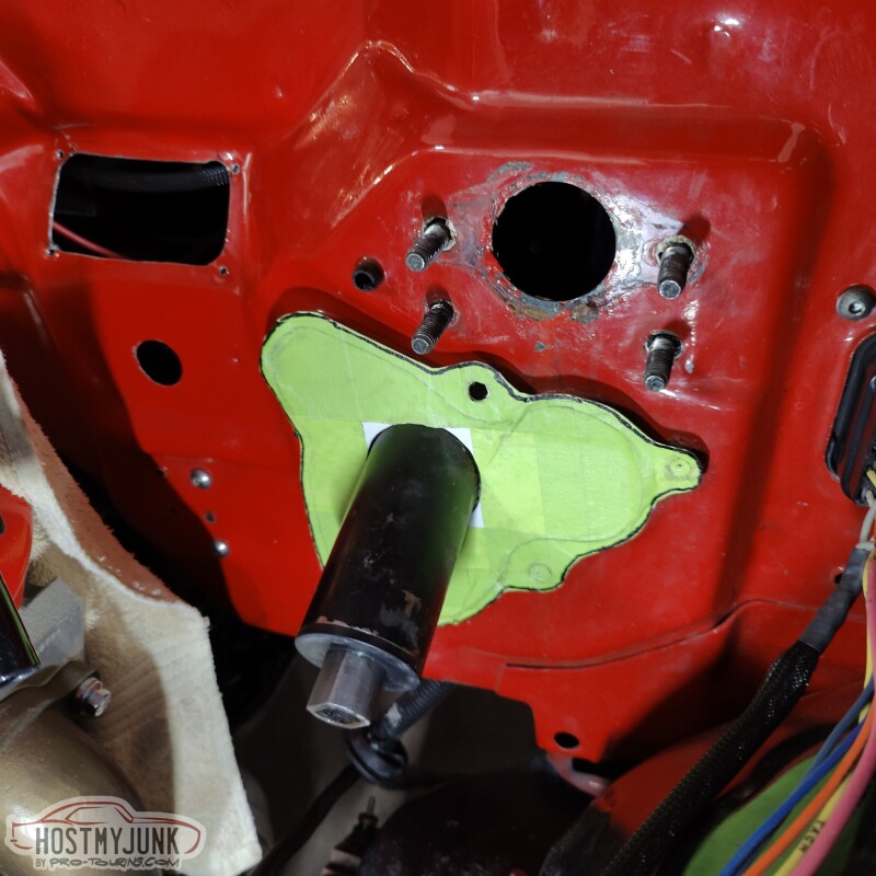
Today I had a few hours to spare, so I drove to Vic's house to make a little close-out panel that would go under the brake booster. In one of the previous pictures you can see the hole that was left after I removed the clutch MC mount. That hole needed to be covered up and I also needed to clean up some of the peeling paint and surface rust that was there.
I scraped the loose paint off and then scrubbed the surface with an abrasive pad. Then I sprayed some primer into a small cup and used a small brush to apply it and then did the same with some black paint. The point wasn't to make it look pretty, but to seal the exposed metal.
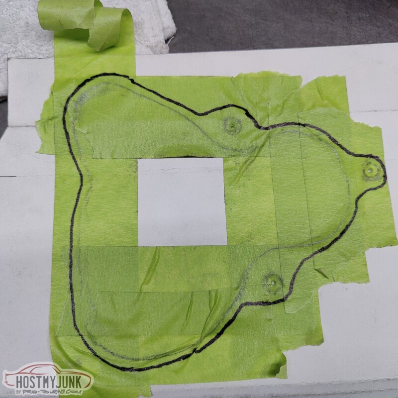
I then started to layer 2" masking tape over the whole area.
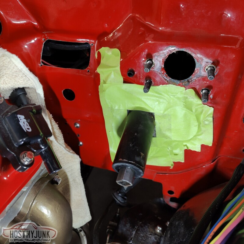
I used a pencil to trace out the outline of the patch that I wanted to cover and also marked out the 3 mounting holes.
I then transferred the masking tape template to some thin cardboard and used a sharpie to draw out the shape that would capture the mounting bolts and that would overlap the opening that I wanted to cover.
I cut the cardboard with some scissors and did a trial fit. Everything was looking pretty good.
I used the cardboard template to transfer the shape and the holes to a piece of 1/8" aluminum plate.
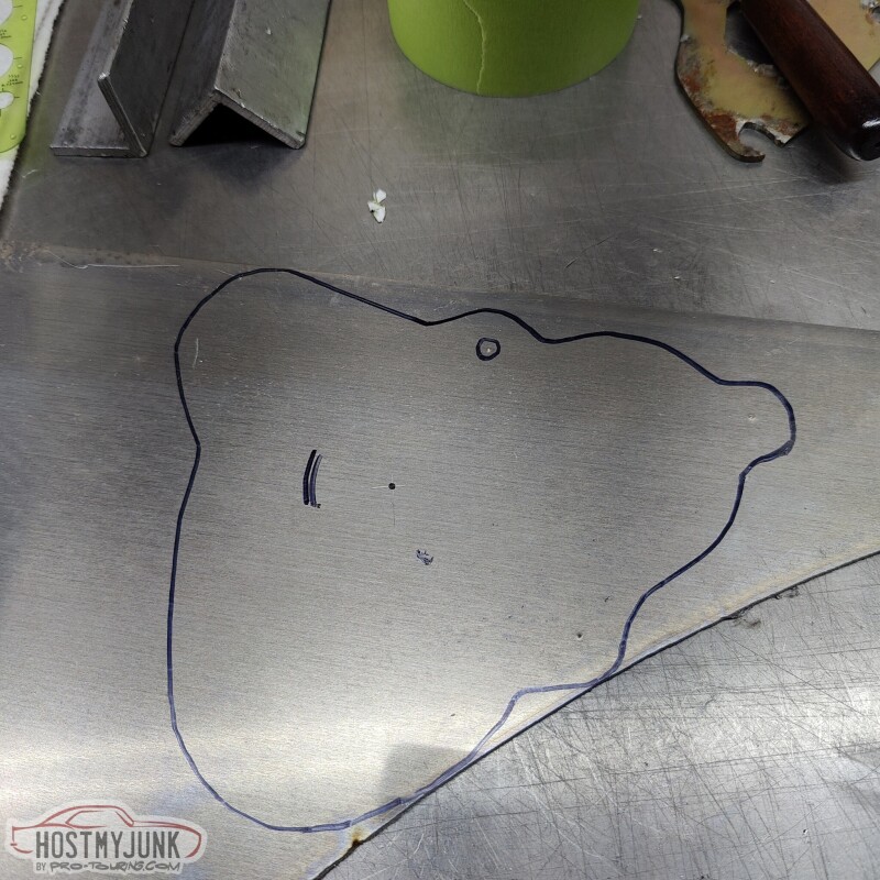
I cut the couch shape on a bandsaw and then used a belt sander the arrive at the final shape. I also used a 2" hole saw to make the hole.
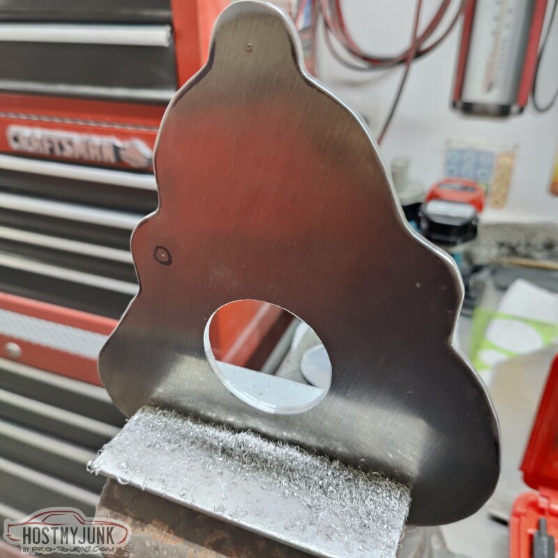
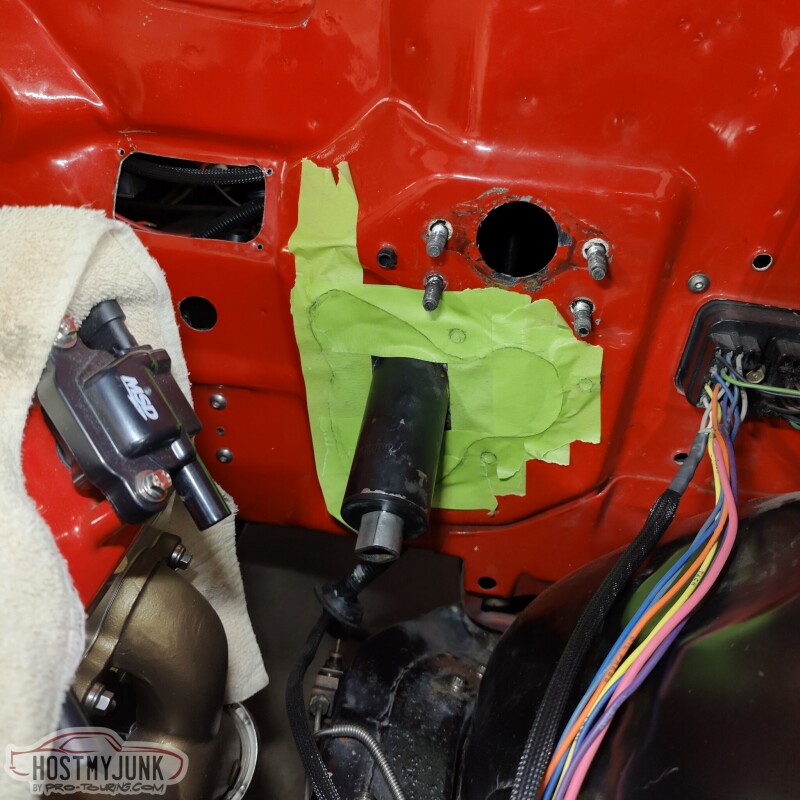
Since the column pokes through the plate at an angle, the opening had to be oval, not round, so I used a file to contour the opening until the panel fit flush against the firewall.
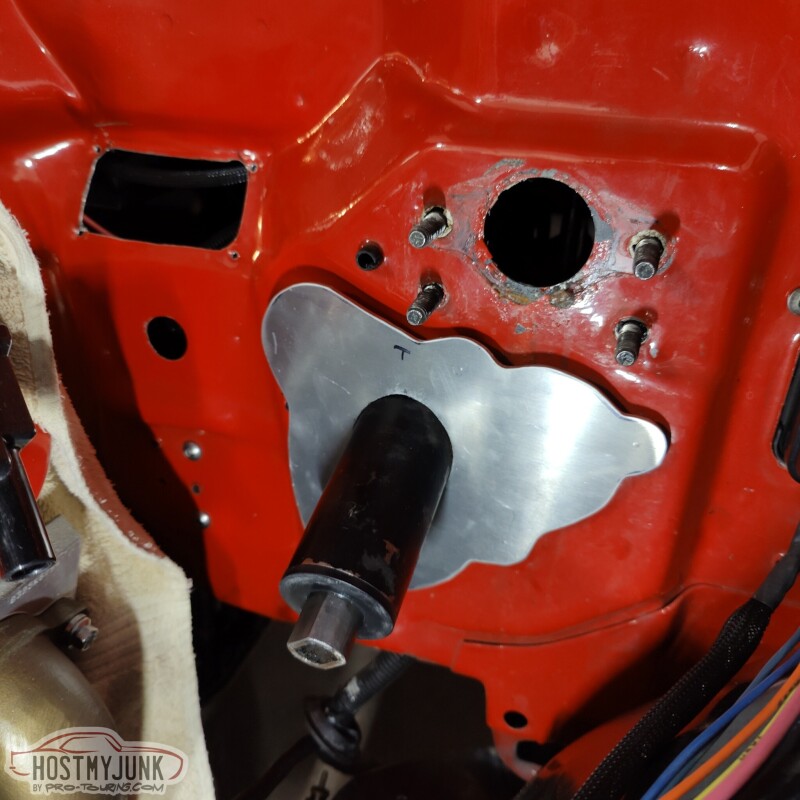
Then I drilled out the 3 mounting holes.
The panel fits really well. It will get painted black and I will use some window mount urethane to seal the plate against the firewall. This will keep water from collecting and keep that area clean and dry. Once the booster is installed, the panel won't really be visible, but I think it adds a finished touch to an area that looks a little raggedy before.
Andrew
Today I had a few hours to spare, so I drove to Vic's house to make a little close-out panel that would go under the brake booster. In one of the previous pictures you can see the hole that was left after I removed the clutch MC mount. That hole needed to be covered up and I also needed to clean up some of the peeling paint and surface rust that was there.
I scraped the loose paint off and then scrubbed the surface with an abrasive pad. Then I sprayed some primer into a small cup and used a small brush to apply it and then did the same with some black paint. The point wasn't to make it look pretty, but to seal the exposed metal.
I then started to layer 2" masking tape over the whole area.
I used a pencil to trace out the outline of the patch that I wanted to cover and also marked out the 3 mounting holes.
I then transferred the masking tape template to some thin cardboard and used a sharpie to draw out the shape that would capture the mounting bolts and that would overlap the opening that I wanted to cover.
I cut the cardboard with some scissors and did a trial fit. Everything was looking pretty good.
I used the cardboard template to transfer the shape and the holes to a piece of 1/8" aluminum plate.
I cut the couch shape on a bandsaw and then used a belt sander the arrive at the final shape. I also used a 2" hole saw to make the hole.
Since the column pokes through the plate at an angle, the opening had to be oval, not round, so I used a file to contour the opening until the panel fit flush against the firewall.
Then I drilled out the 3 mounting holes.
The panel fits really well. It will get painted black and I will use some window mount urethane to seal the plate against the firewall. This will keep water from collecting and keep that area clean and dry. Once the booster is installed, the panel won't really be visible, but I think it adds a finished touch to an area that looks a little raggedy before.
Andrew
Thread Starter
Joined: Mar 2003
Posts: 10,604
Likes: 1,881
From: Little Austin
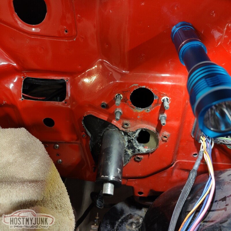
Today wasn't terribly productive. I managed to install the new Borgeson steering box. Overall it looked pretty similar to my ancient AGR steering box, with the exception of having 4 mounting ears instead of 3. My frame only has 3 mounts, so the 4th is just, there...
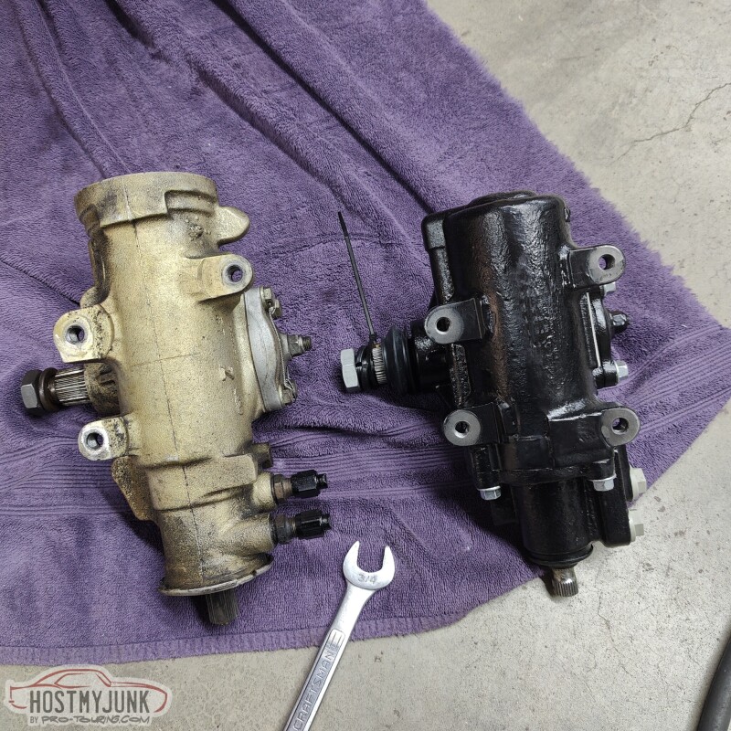
I was able to reuse the fittings from the old box on the new box. The Borgeson box uses metric fittings with o-rings, which were the same size as my old AGR box.
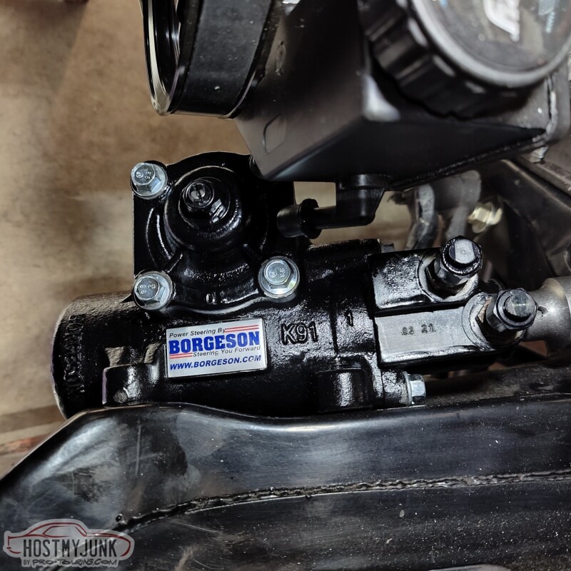
The Borgeson box also uses a slightly smaller input shaft.
Andrew
I was able to reuse the fittings from the old box on the new box. The Borgeson box uses metric fittings with o-rings, which were the same size as my old AGR box.
The Borgeson box also uses a slightly smaller input shaft.
Andrew

Thread Starter
Joined: Mar 2003
Posts: 10,604
Likes: 1,881
From: Little Austin
John was referring to the location of the steering arms relative to the kingpin angle. All GM A-bodies have the steering arms forward on the spindle (front steer). His Camaro has the steering arms towards the rear of the spindle (rear steer).
Andrew
Andrew
Thread Starter
Joined: Mar 2003
Posts: 10,604
Likes: 1,881
From: Little Austin
Before the next update, I want to send a shout out to a great vendor. It is not often that a company surpasses my expectations, but Stainless Bros definitely has.
This is how they packaged one half of the 4" v-band clams that I received from them.

Each v-band was in it's own box and the clamp itself was in its own sealed bag.
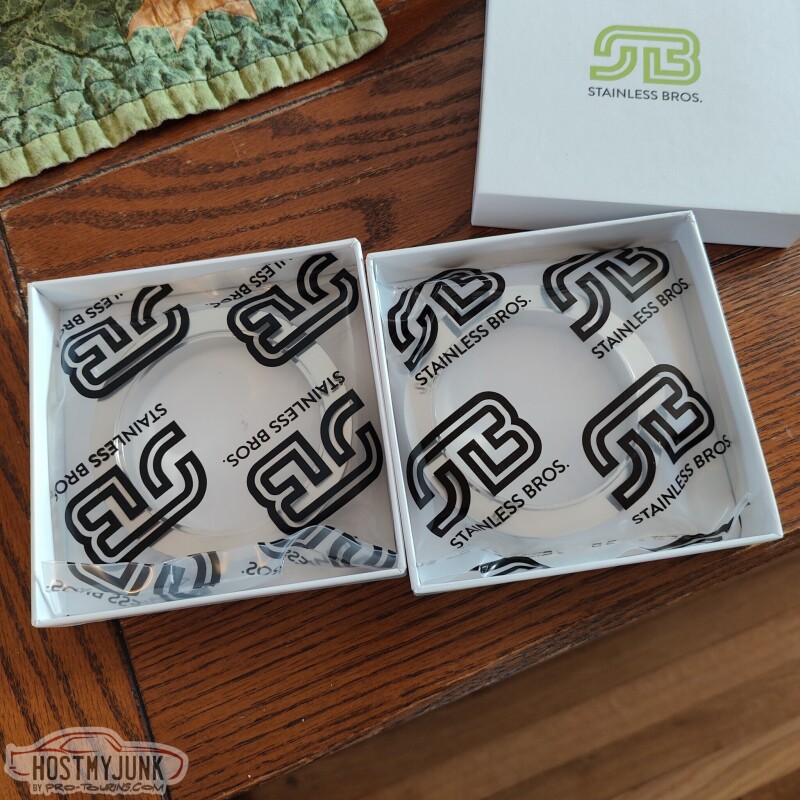
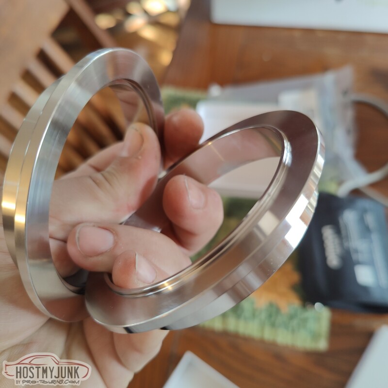
The v-bands themselves are like jewelry. Each half indexes into the other, which is a great feature that makes it easier to align the pipes.
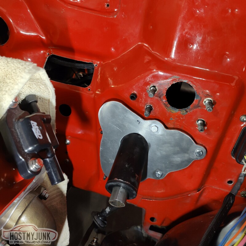
I was also able to make it out to my local Napa store and picked up a roll of 5/16" butyl tape. I used it so seal the back of the close-out panel that I made the other day.
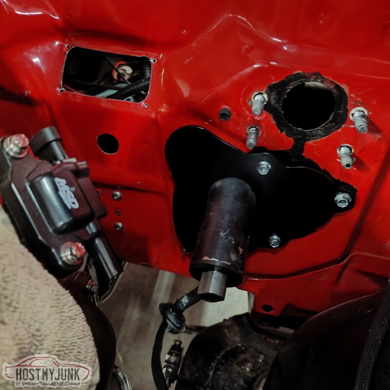
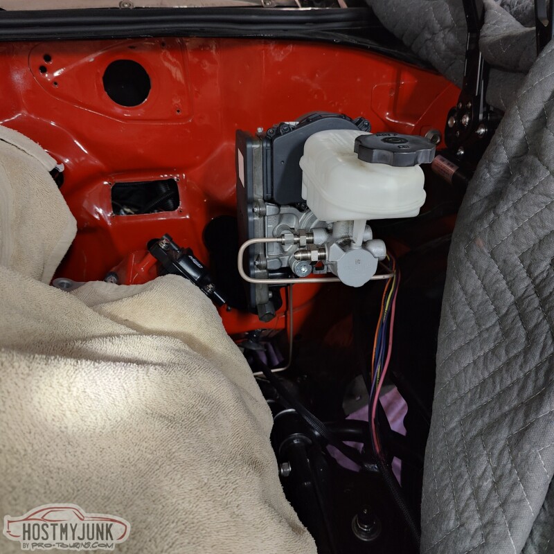
I was also able to use the boot that came from DSE. This is a boot they use with their low angle vacuum assisted booster.
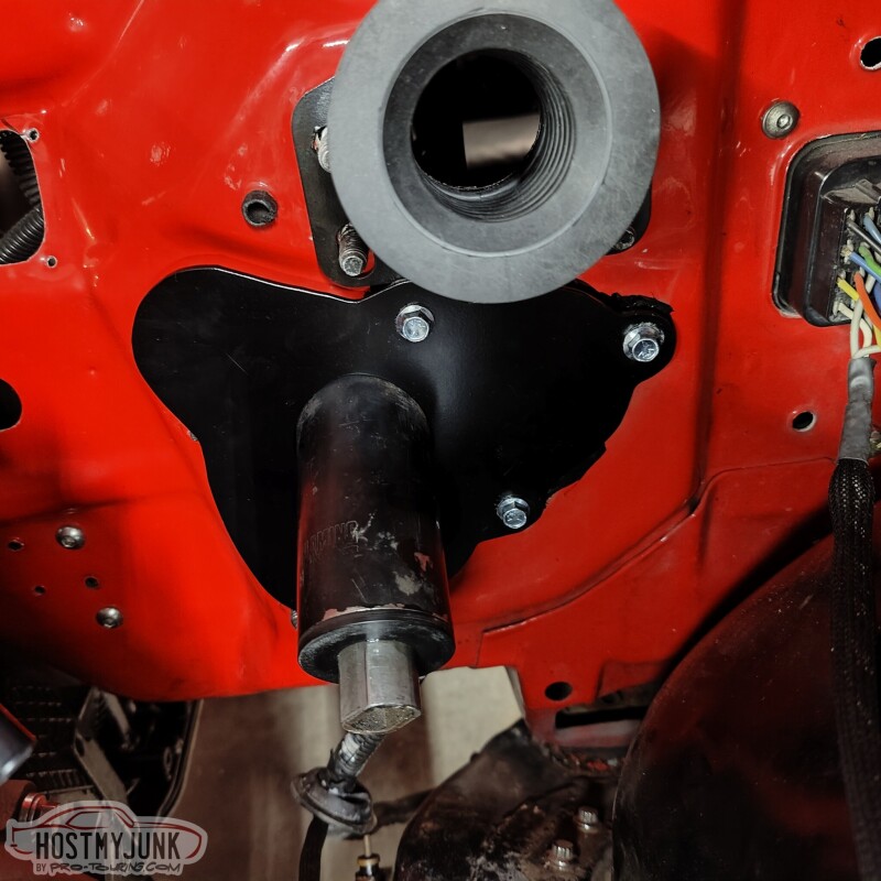
Once the iBooster is installed the plate isn't really visible.
I also started on the new brake lines. I am using 3/16" NiCopp for the front brakes and 1/4" NiCopp for the rear brakes. The 12mm flare to AN adapters are from Earl's. I am not really happy with how far they stick out, but I am not sure what there is to do about it.
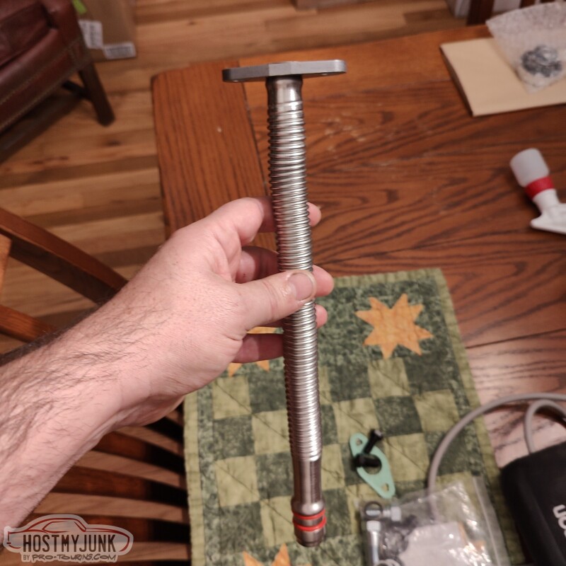
I also got this Cummins turbo drain as a starting point for my drain. More on that in a future update.
Andrew
This is how they packaged one half of the 4" v-band clams that I received from them.
Each v-band was in it's own box and the clamp itself was in its own sealed bag.
The v-bands themselves are like jewelry. Each half indexes into the other, which is a great feature that makes it easier to align the pipes.
I was also able to make it out to my local Napa store and picked up a roll of 5/16" butyl tape. I used it so seal the back of the close-out panel that I made the other day.
I was also able to use the boot that came from DSE. This is a boot they use with their low angle vacuum assisted booster.
Once the iBooster is installed the plate isn't really visible.
I also started on the new brake lines. I am using 3/16" NiCopp for the front brakes and 1/4" NiCopp for the rear brakes. The 12mm flare to AN adapters are from Earl's. I am not really happy with how far they stick out, but I am not sure what there is to do about it.
I also got this Cummins turbo drain as a starting point for my drain. More on that in a future update.
Andrew
Thread Starter
Joined: Mar 2003
Posts: 10,604
Likes: 1,881
From: Little Austin
I spent a little time at Vic's today working on various odds and ends.
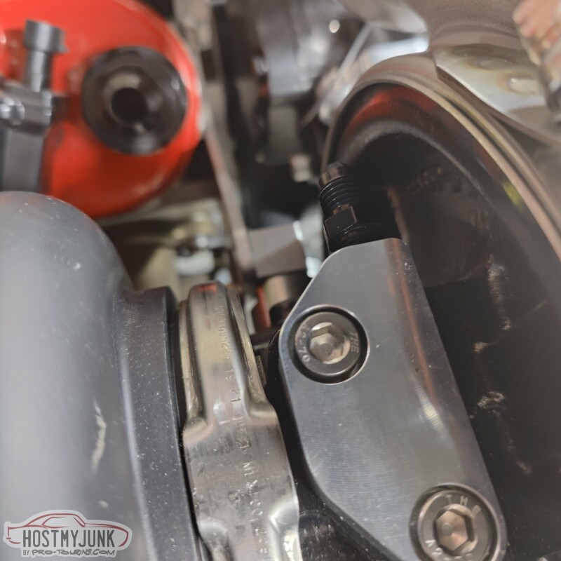
This is a clever little part from Motion Raceworks. It's an oil inlet block that bolts to the top of the oil feed hole and seals with an o-ring. It then points the oil feed line straight out the side. This will connect to the oil feed line, which at the moment terminates at the front of the passenger side head.
A few days back Vic also made this fantastic mount for the Dominator ECU. It bolts in place of the glove box and will allow me easy access to the ECU connectors. Ignore the duct tape. I will be placing an order with Vintage Air soon to clean up the under-dash ducting in anticipation of having working AC in the car.
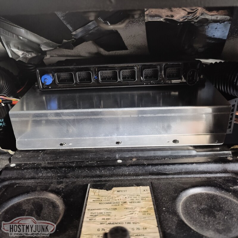
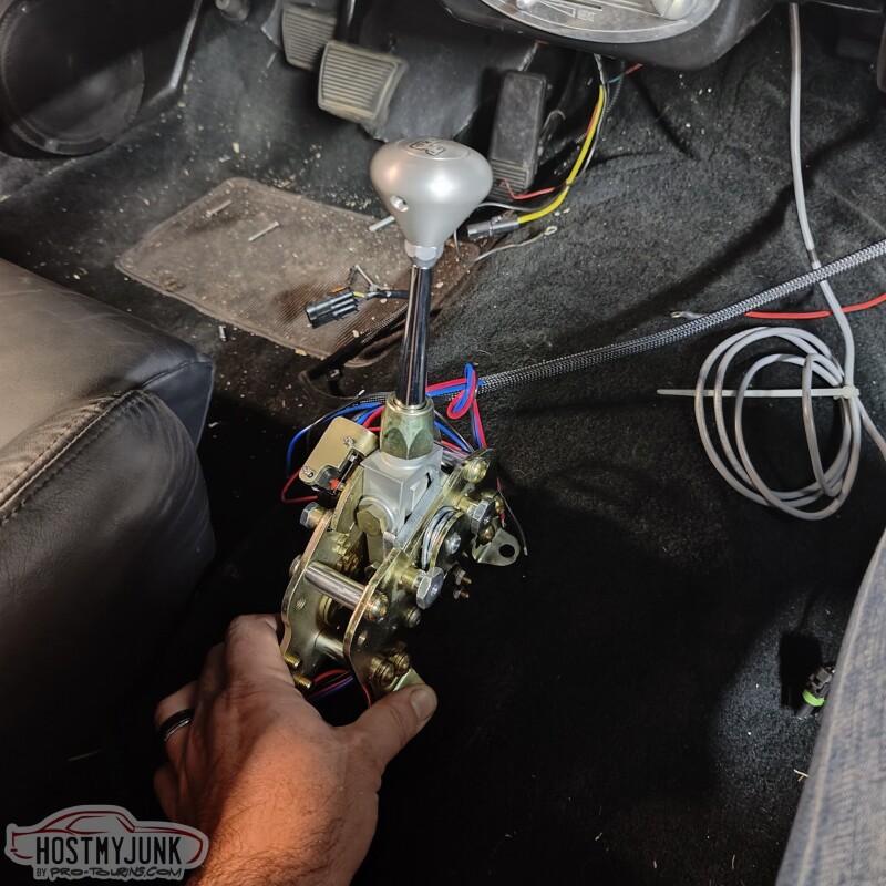
I also brought the shifter to see how it might fit inside the car. In the picture I have it sitting over the hole where my manual shifter was located. It is slightly offset to the driver's side. I am not really sure about the shifter placement yet.
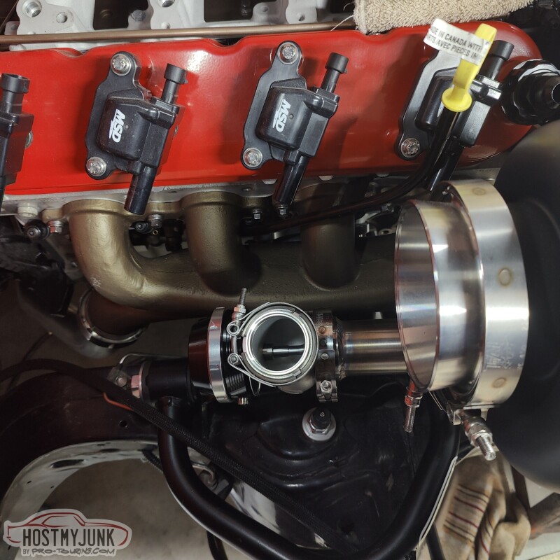
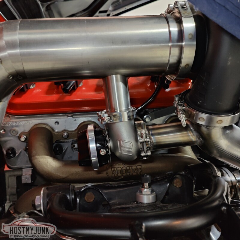
Vic worked out the final placement of the waste gate and started on the fabrication of the needed plumbing.
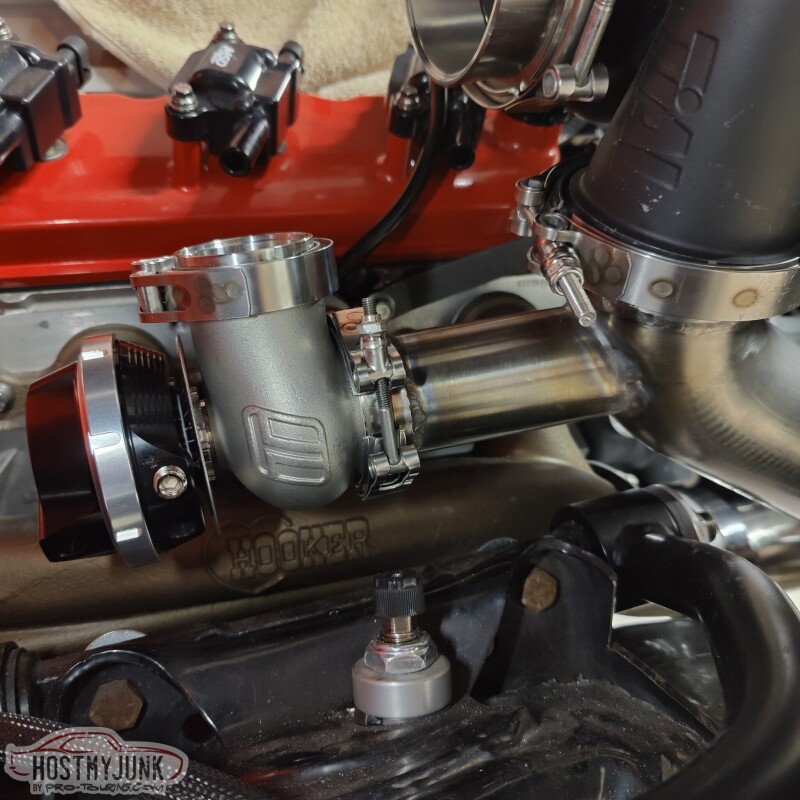
It should have good priority flow in this location and provide an easy path to route the exhaust from the waste gate back into the downpipe.
Andrew
This is a clever little part from Motion Raceworks. It's an oil inlet block that bolts to the top of the oil feed hole and seals with an o-ring. It then points the oil feed line straight out the side. This will connect to the oil feed line, which at the moment terminates at the front of the passenger side head.
A few days back Vic also made this fantastic mount for the Dominator ECU. It bolts in place of the glove box and will allow me easy access to the ECU connectors. Ignore the duct tape. I will be placing an order with Vintage Air soon to clean up the under-dash ducting in anticipation of having working AC in the car.
I also brought the shifter to see how it might fit inside the car. In the picture I have it sitting over the hole where my manual shifter was located. It is slightly offset to the driver's side. I am not really sure about the shifter placement yet.
Vic worked out the final placement of the waste gate and started on the fabrication of the needed plumbing.
It should have good priority flow in this location and provide an easy path to route the exhaust from the waste gate back into the downpipe.
Andrew
Thread Starter
Joined: Mar 2003
Posts: 10,604
Likes: 1,881
From: Little Austin
Finally I can say I did a few things on the car, mostly by myself...LOL
Yesterday I received the last few parts that I needed to finish the new brake lines from the MC to the distribution block.
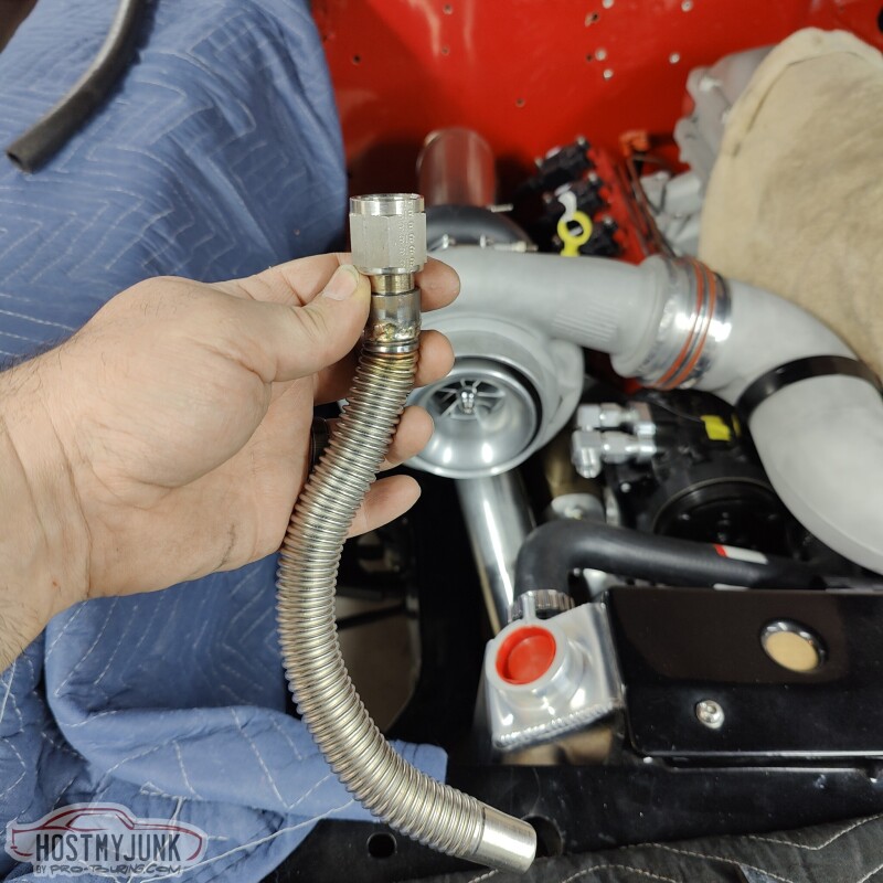
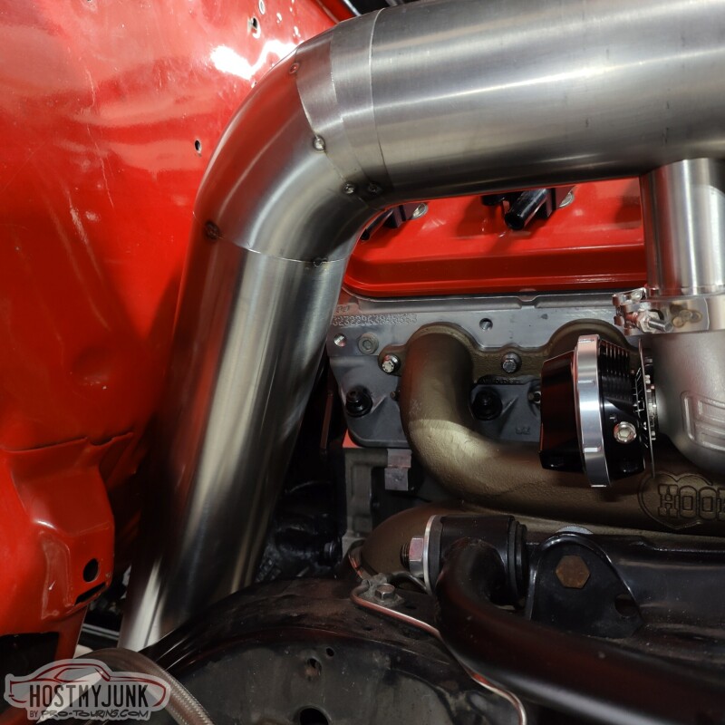
I also welded on this oil drain tube. Vic made a couple of adapters on the lathe and I welded it together. The welds are horrible, but it should hold. Because of how everything is situated, the drain has to take a slight jog to the passenger side immediately after coming out of the turbo. This is a turbo drain for a Cummins something or other. It is fairly flexible and is made out of stainless steel, so it is relatively easy to work with.
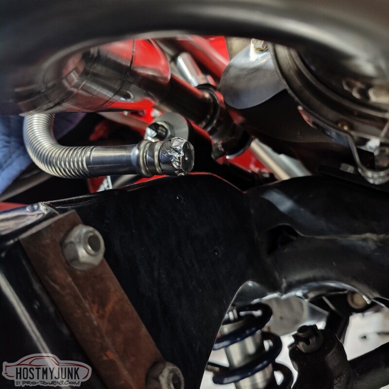
Once it makes the jog to the left is has to sweep right, under the up-pipe and under the exhaust manifold, then towards the drain in the side of the oil pan. I will extend this tube so it is all metal under the hottest pipes and there will be a short section of hose connecting the drain to the oil pan.
The waste gate discharge is tacked to the downpipe.
The downpipe itself is also tacked in place.
There is also a 4" v-band at the end of the downpipe that connects to this pipe that shoots the exhaust straight back.
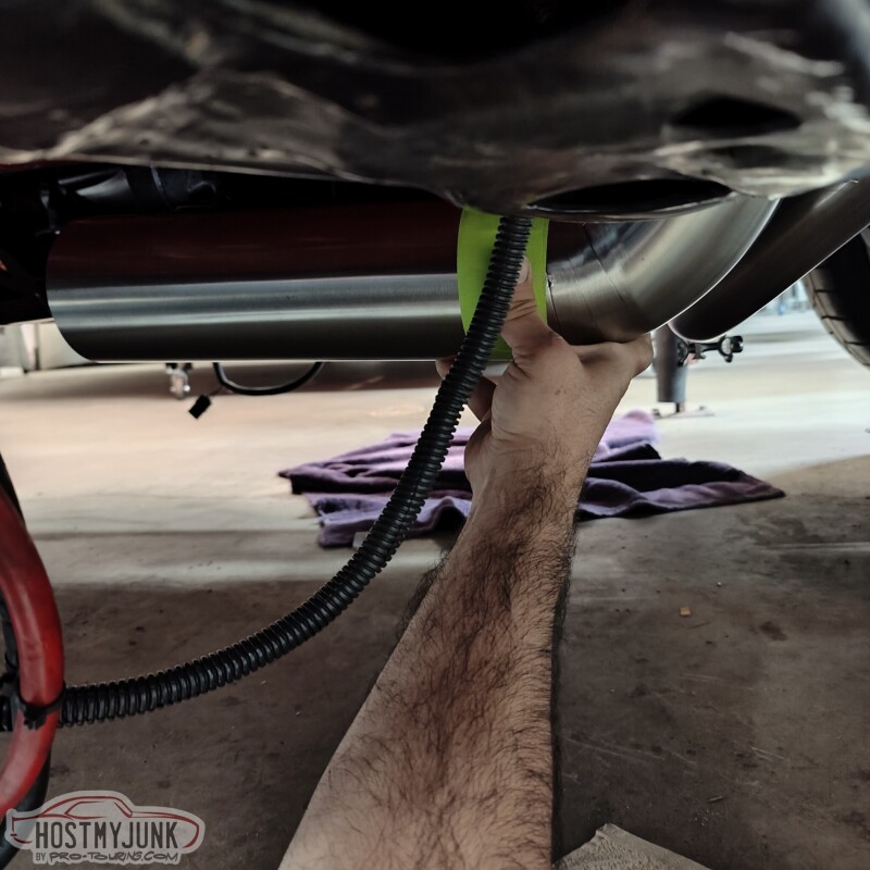
I am not sure yet what's going to happen with the exhaust once it is past the transmission crossmember.
Andrew
Yesterday I received the last few parts that I needed to finish the new brake lines from the MC to the distribution block.
I also welded on this oil drain tube. Vic made a couple of adapters on the lathe and I welded it together. The welds are horrible, but it should hold. Because of how everything is situated, the drain has to take a slight jog to the passenger side immediately after coming out of the turbo. This is a turbo drain for a Cummins something or other. It is fairly flexible and is made out of stainless steel, so it is relatively easy to work with.
Once it makes the jog to the left is has to sweep right, under the up-pipe and under the exhaust manifold, then towards the drain in the side of the oil pan. I will extend this tube so it is all metal under the hottest pipes and there will be a short section of hose connecting the drain to the oil pan.
The waste gate discharge is tacked to the downpipe.
The downpipe itself is also tacked in place.
There is also a 4" v-band at the end of the downpipe that connects to this pipe that shoots the exhaust straight back.
I am not sure yet what's going to happen with the exhaust once it is past the transmission crossmember.
Andrew