
First turbo build, 70 GTO...

LS1Tech Sponsor


Joined: Jan 2008
Posts: 2,230
Likes: 1,515
From: Ohio, Georgia, Nevada, Texas
@02redchevy,
We offer a plethora of self-adhesive heat barrier products with options in our own brand. Feel free to shoot us a PM for any further assistance!
We offer a plethora of self-adhesive heat barrier products with options in our own brand. Feel free to shoot us a PM for any further assistance!

Thread Starter


Joined: Mar 2003
Posts: 10,604
Likes: 1,881
From: Little Austin
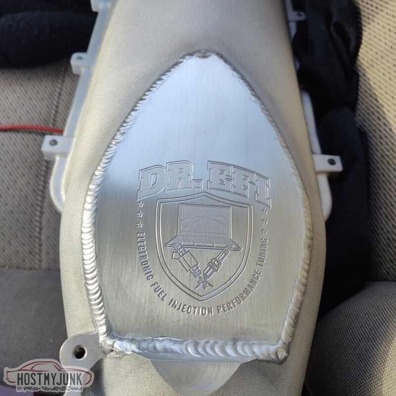
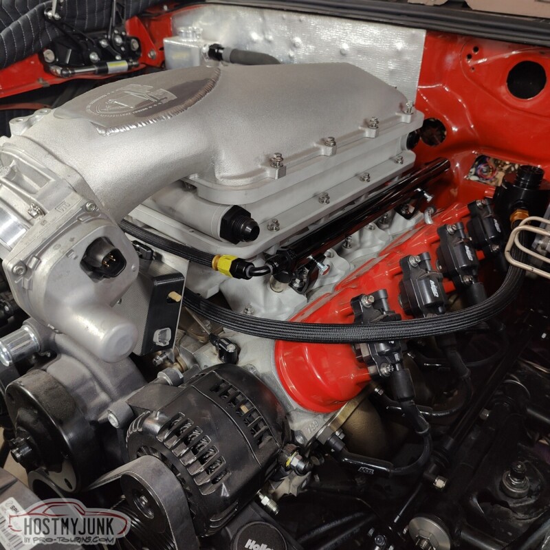
I took my intake to Hot Rod Express, where they welded the engraved manifold cover plate to the Holley intake lid.
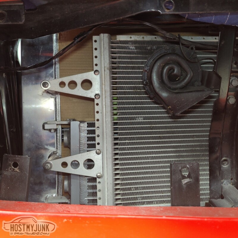
Today was the day that I wanted to get the heat exchanger mounted and start thinking about running the plumbing (so much plumbing in this car!!!) the A2W intercooler system. When I originally asked Vic to mount the heat exchanger to the radiator, I really had no idea how things would be plumbed. I had him mount the heat exchanger with the inlet and outlet (dual pass) on the driver's side. Clearly this is not going to work.
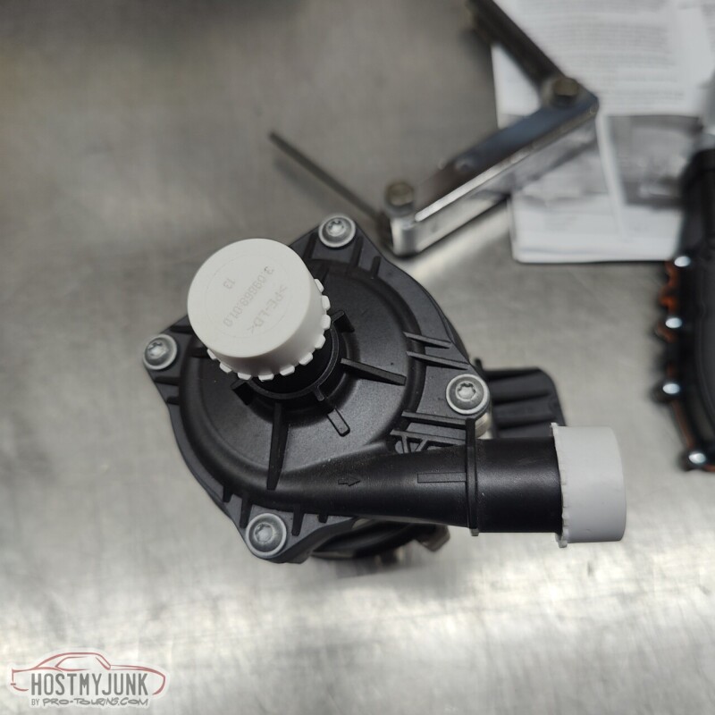
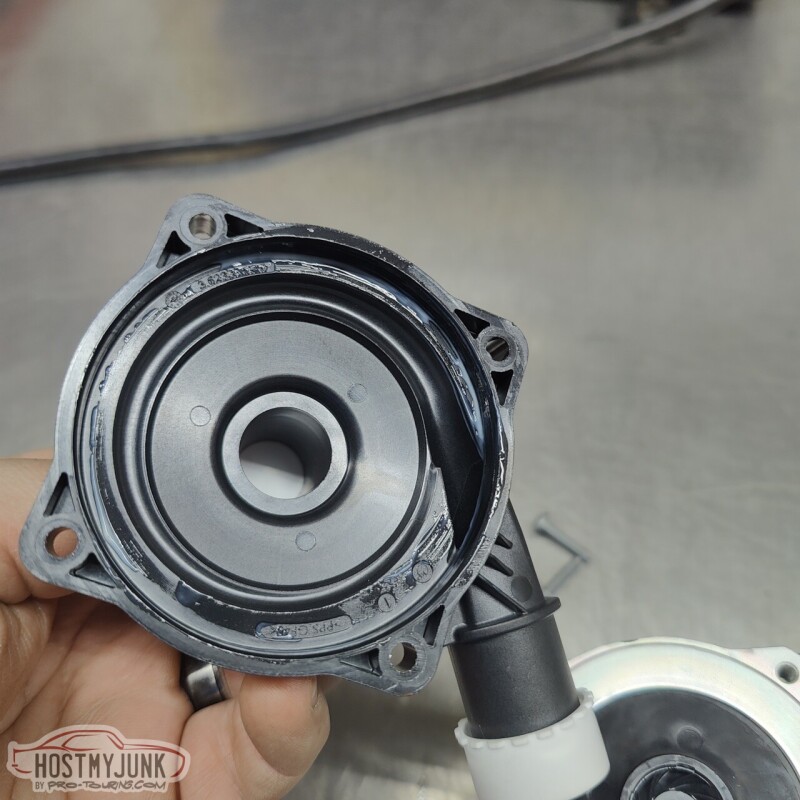
With the intercooler, fill tank, and circulation pump in place, it was clear that the best option would be to have the input and outlet on the passenger side. Before digging into that further I wanted to make sure that the circulation pump fittings would be oriented in the correct direction. I emailed Tobias at Tecomotive and he quickly responded that the pump inlet and outlet cover can be clocked in any of the 4 positions relative to the pump body.
I unscrewed the top and it sure doesn't look very fancy in here, but this pump is supposed to move A LOT of water.
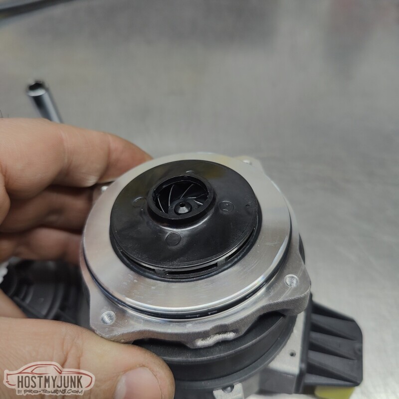
Not much to see here....
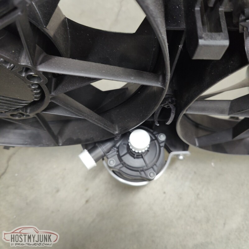
I positioned the pump body in such a way that the connector was close to the fan shroud so that the wires for the pump could be routed along the bottom of the shroud.
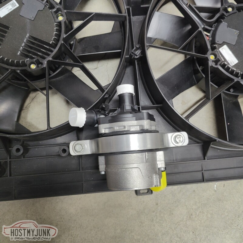
I clocked the top so the outlet would face the passenger side (the top is the inlet).
I also pulled both grill inserts so it would be easier to work in front of the radiator. As I was going along, I always had to make sure that I could get to everything without having to pull the grills, because once the radiator is installed, there is no way to access the grill hardware.
Here you can see that the heat exchanger was flipped (the drain is now at the top and can't be used). We couldn't rotate the heat exchanger because that would have required a complete reworking of the mounts and I did not want to do all that. I can live without a drain.
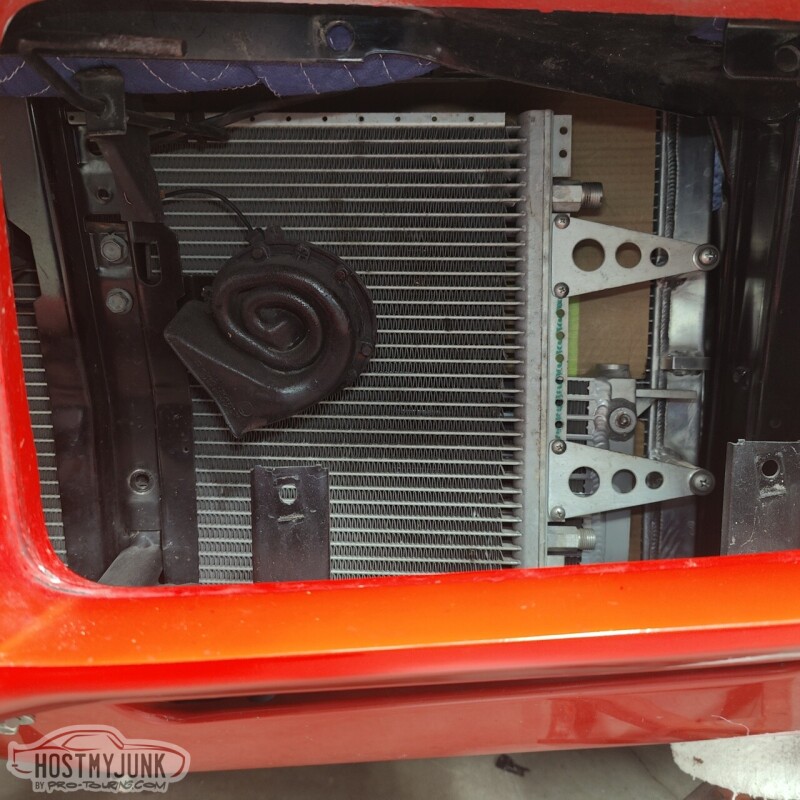
There is a lot more room on the passenger side for plumbing because the radiator core is slightly offset to the driver's side (note the larger tank on the passenger side).
With that orientation locked in, we moved to the bench where some minor fiddling had to be done to make the mounts work.
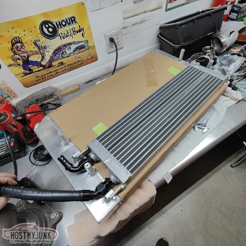
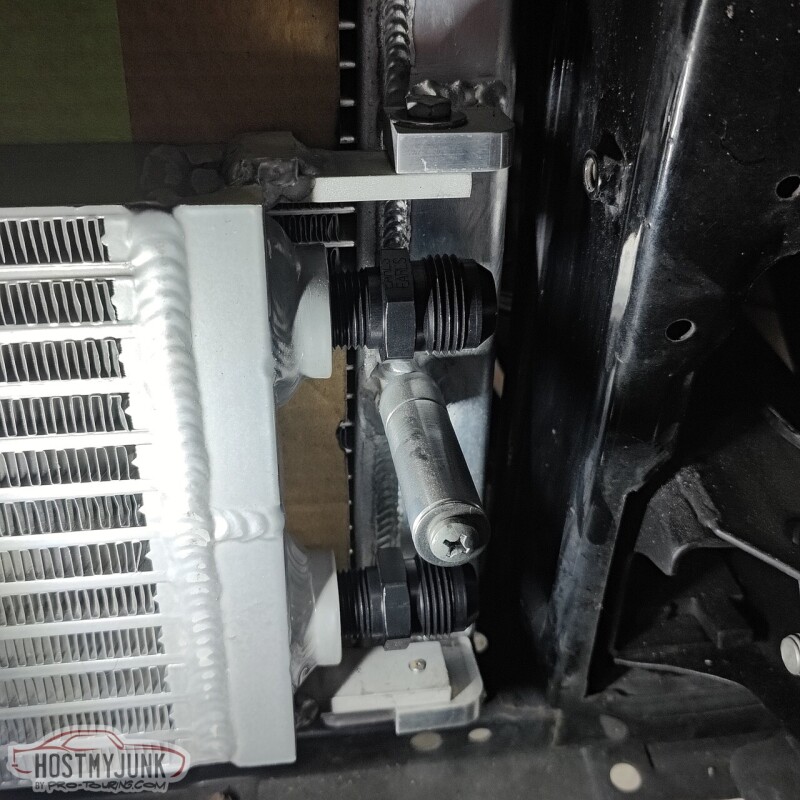
Both the inlet and outlet hoses fit pretty well using 90 degree fittings. With the fans removed and the radiator top tilted back, there is enough room to access these fittings from the top.
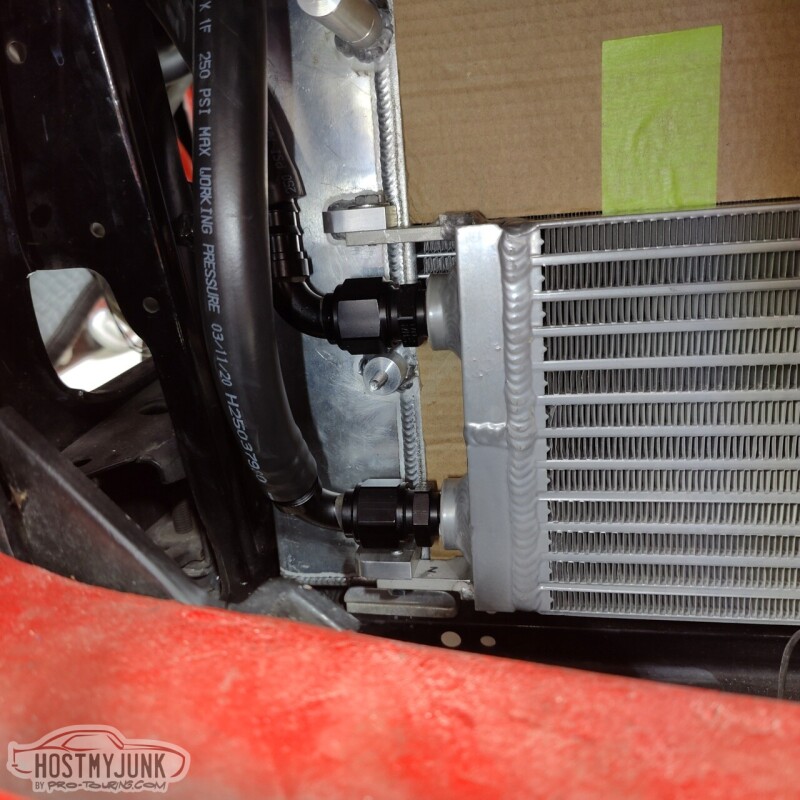
I also trimmed the core support slightly so that the hoses can pass in front of the radiator. You can also see the Low Doller Motorsports temperature/pressure combo sensor in the cooling system.
I still have to finalize the exact hose routing, but this is pretty good progress.
Andrew
Today was the day that I wanted to get the heat exchanger mounted and start thinking about running the plumbing (so much plumbing in this car!!!) the A2W intercooler system. When I originally asked Vic to mount the heat exchanger to the radiator, I really had no idea how things would be plumbed. I had him mount the heat exchanger with the inlet and outlet (dual pass) on the driver's side. Clearly this is not going to work.
With the intercooler, fill tank, and circulation pump in place, it was clear that the best option would be to have the input and outlet on the passenger side. Before digging into that further I wanted to make sure that the circulation pump fittings would be oriented in the correct direction. I emailed Tobias at Tecomotive and he quickly responded that the pump inlet and outlet cover can be clocked in any of the 4 positions relative to the pump body.
I unscrewed the top and it sure doesn't look very fancy in here, but this pump is supposed to move A LOT of water.
Not much to see here....
I positioned the pump body in such a way that the connector was close to the fan shroud so that the wires for the pump could be routed along the bottom of the shroud.
I clocked the top so the outlet would face the passenger side (the top is the inlet).
I also pulled both grill inserts so it would be easier to work in front of the radiator. As I was going along, I always had to make sure that I could get to everything without having to pull the grills, because once the radiator is installed, there is no way to access the grill hardware.
Here you can see that the heat exchanger was flipped (the drain is now at the top and can't be used). We couldn't rotate the heat exchanger because that would have required a complete reworking of the mounts and I did not want to do all that. I can live without a drain.
There is a lot more room on the passenger side for plumbing because the radiator core is slightly offset to the driver's side (note the larger tank on the passenger side).
With that orientation locked in, we moved to the bench where some minor fiddling had to be done to make the mounts work.
Both the inlet and outlet hoses fit pretty well using 90 degree fittings. With the fans removed and the radiator top tilted back, there is enough room to access these fittings from the top.
I also trimmed the core support slightly so that the hoses can pass in front of the radiator. You can also see the Low Doller Motorsports temperature/pressure combo sensor in the cooling system.
I still have to finalize the exact hose routing, but this is pretty good progress.
Andrew
Thread Starter
Joined: Mar 2003
Posts: 10,604
Likes: 1,881
From: Little Austin
I had mocked up the shifter a while back and it turned out that the 4 foot cable that was included with the Lokar shifter was not going to be long enough. So I ordered a 6 foot cable (which honestly could be 7 feet) from Summit and after it was defrosted in the Texas warehouse, I received it yesterday.
So it was time to put the big boy pants on and poke some holes to mount the shifter. I positioned it in such a way that with the shifter in Drive, I could, very naturally, put my hand on the shift level and slide it to the right and use the forward and backwards tap shift feature.
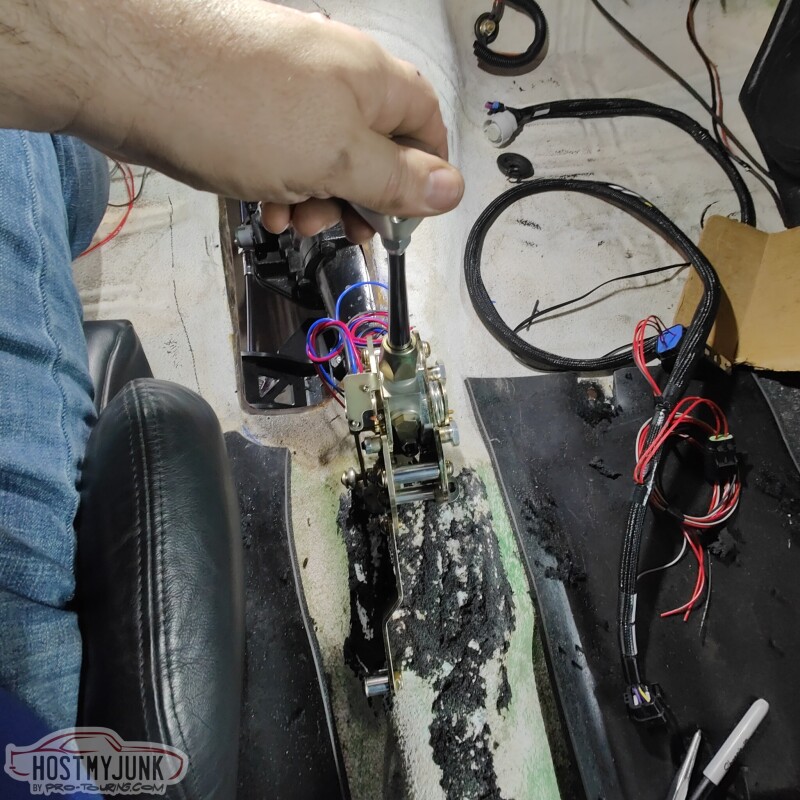
I drilled the first hole and shockingly it lined up perfectly where I intended it to go. I mounted the shifter and marked the other hole.
I used nut-serts (riv-nuts) inside the hole and temporarily mounted the shifter.
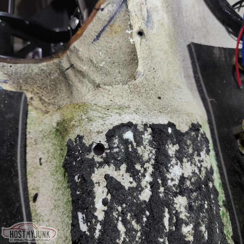
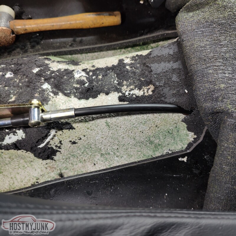
I did a little more measuring and drilled a hole in the floor for the shifter cable. ICT Billet posted a teaser on their Instagram about their new shift cable pass-through and I have been bugging them about it for weeks. I am hoping it will be available soon so I can use it to seal the hole.
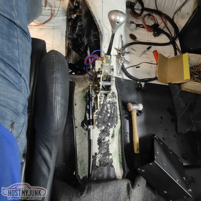
For the front of the shifter, Vic whipped up a simple bracket and we (yes, I welded one side and he the other...thanks you...) welded it to the floor.
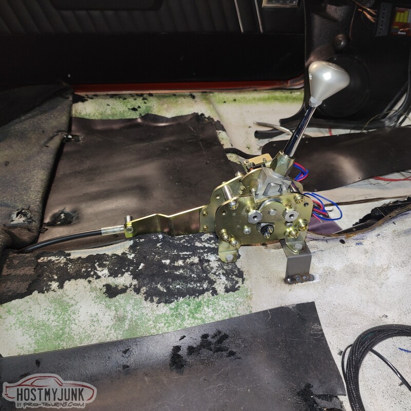
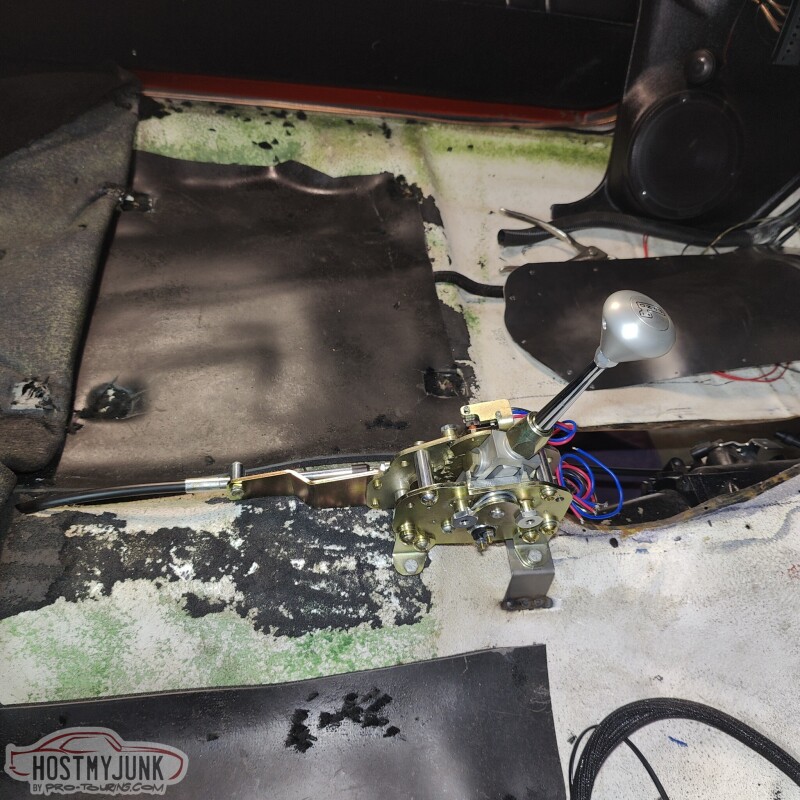
The shifter feels pretty good, but there are some minor adjustments that need to be made still.
Andrew
So it was time to put the big boy pants on and poke some holes to mount the shifter. I positioned it in such a way that with the shifter in Drive, I could, very naturally, put my hand on the shift level and slide it to the right and use the forward and backwards tap shift feature.
I drilled the first hole and shockingly it lined up perfectly where I intended it to go. I mounted the shifter and marked the other hole.
I used nut-serts (riv-nuts) inside the hole and temporarily mounted the shifter.
I did a little more measuring and drilled a hole in the floor for the shifter cable. ICT Billet posted a teaser on their Instagram about their new shift cable pass-through and I have been bugging them about it for weeks. I am hoping it will be available soon so I can use it to seal the hole.
For the front of the shifter, Vic whipped up a simple bracket and we (yes, I welded one side and he the other...thanks you...) welded it to the floor.
The shifter feels pretty good, but there are some minor adjustments that need to be made still.
Andrew
Thread Starter
Joined: Mar 2003
Posts: 10,604
Likes: 1,881
From: Little Austin
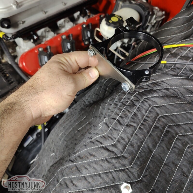
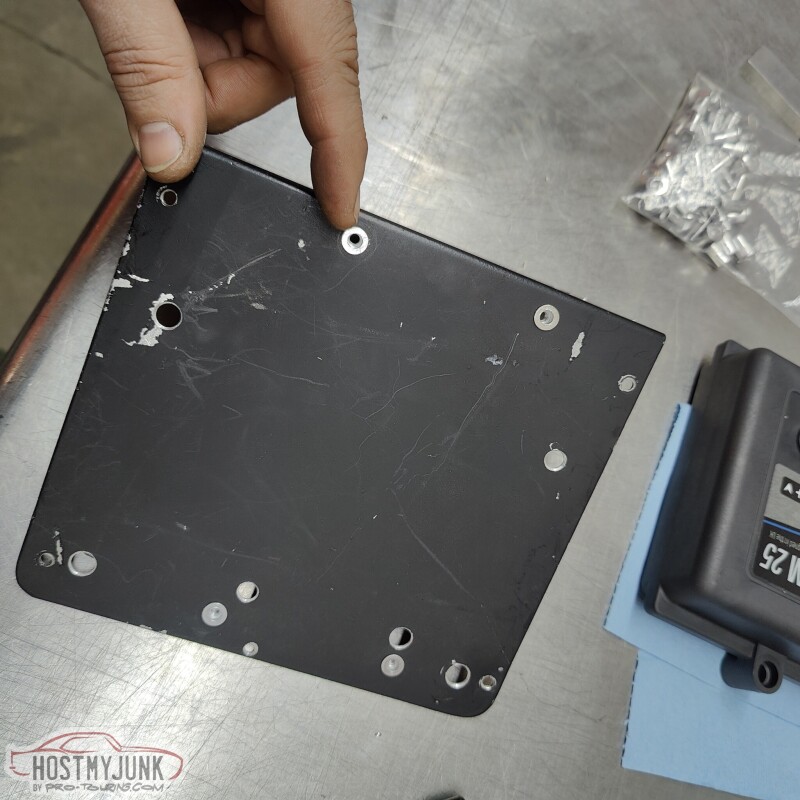
My friend Blake designed and 3D priced a cover the the boost solenoids.
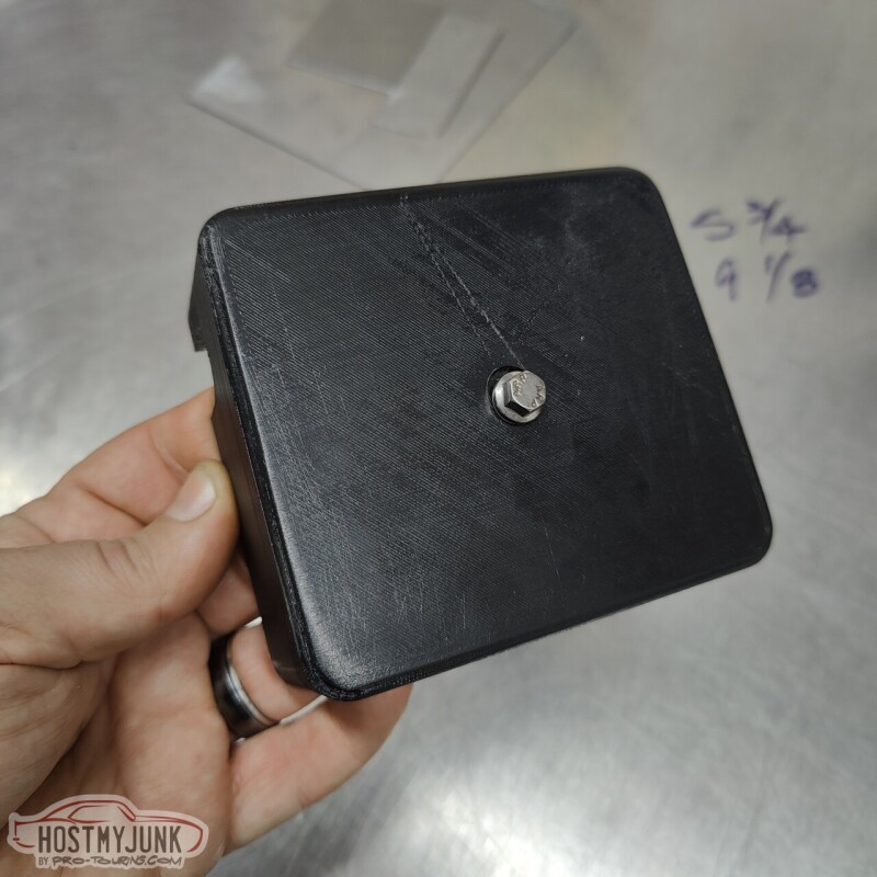
He included a cut-out on the side so that I can mount a Deutsch 4 connector bulkhead fitting, instead of the two connectors that were on the solenoids before.
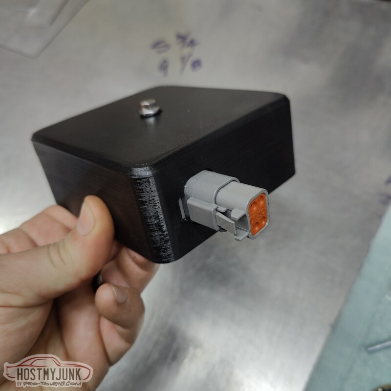
Both Vic and I liked the raw 3D printed look of the sides, but the top was not as pretty. So Vic applied some vinyl to the top.
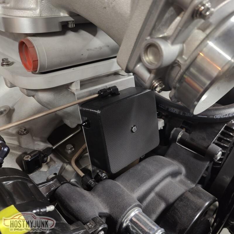
The mounting plate itself is pretty thin, so in order to tap a hole for the hold down bolt, I drilled a small hole and used a punch to gradually enlarge the hole. This folds the soft aluminum out and gives more material to tap, making it as good as a captive nut.
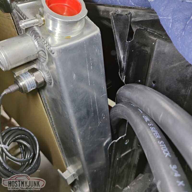
I also made the hose that gos from the fill tank to the top of the heat exchanger.
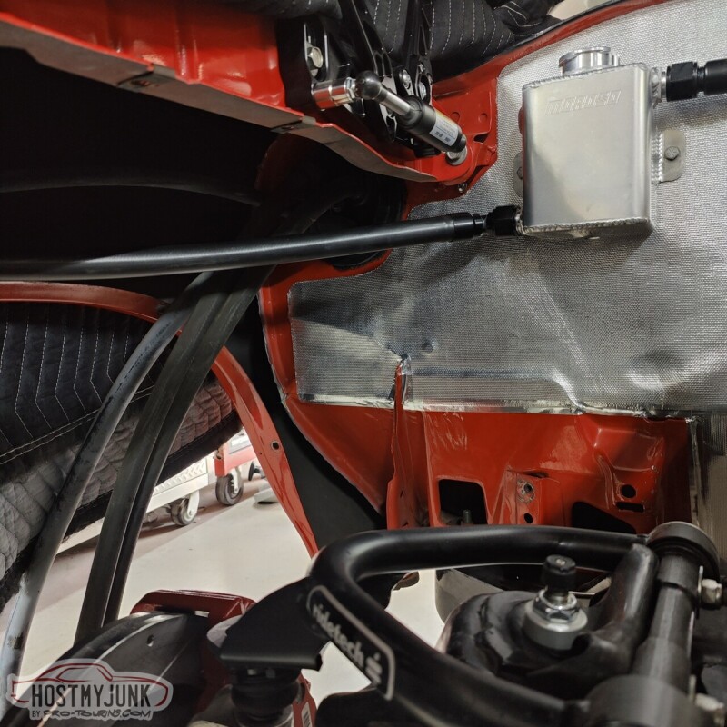
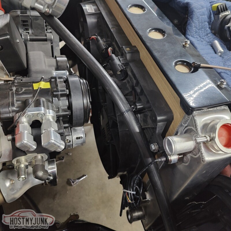
Hear are the two heat exchanger lines where they slip between the core support and the radiator.
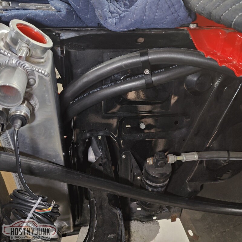
The hose from the bottom of the heat exchanger loops towards the fender, then comes over the fan, and then down into the top of the pump.
I also took the turbo off so that I could rattle can the turbo support bracket.
Andrew
He included a cut-out on the side so that I can mount a Deutsch 4 connector bulkhead fitting, instead of the two connectors that were on the solenoids before.
Both Vic and I liked the raw 3D printed look of the sides, but the top was not as pretty. So Vic applied some vinyl to the top.
The mounting plate itself is pretty thin, so in order to tap a hole for the hold down bolt, I drilled a small hole and used a punch to gradually enlarge the hole. This folds the soft aluminum out and gives more material to tap, making it as good as a captive nut.
I also made the hose that gos from the fill tank to the top of the heat exchanger.
Hear are the two heat exchanger lines where they slip between the core support and the radiator.
The hose from the bottom of the heat exchanger loops towards the fender, then comes over the fan, and then down into the top of the pump.
I also took the turbo off so that I could rattle can the turbo support bracket.
Andrew
Thread Starter
Joined: Mar 2003
Posts: 10,604
Likes: 1,881
From: Little Austin
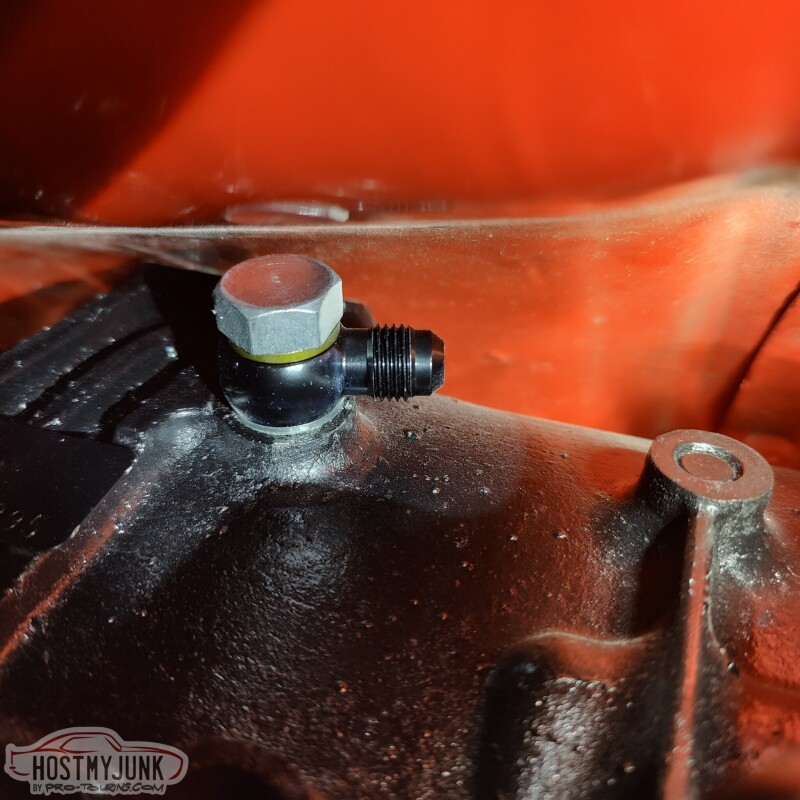
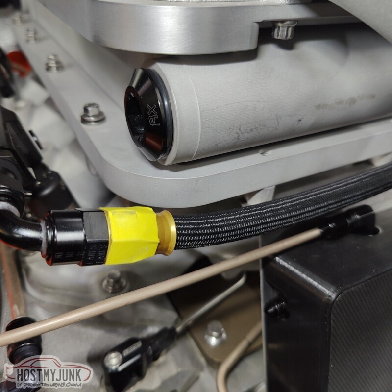
Today was another plumbing day. This time it was time to plumb the transmission cooler. Here is a little tip when working with push-lock style hose.
Add a union to the fitting and snug it down. This does two things:
1. If using a 45 or 90 degree fitting it keeps the nipple from trying to move around.
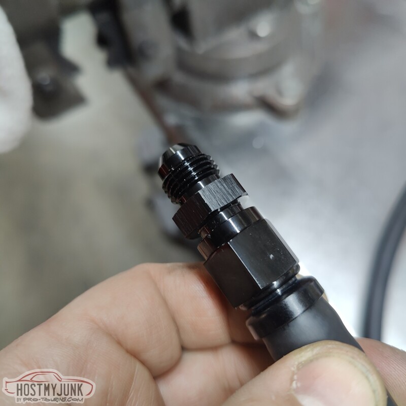
2. When putting the fitting in the vise to hold it, it keeps the the nut from crushing and becoming out of round.
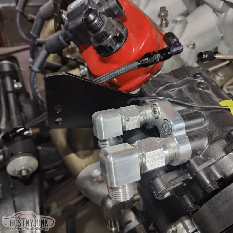
This is the rear fitting on the transmission. The picture actually makes it look like there is a lot of clearance, but in reality it is very tight.
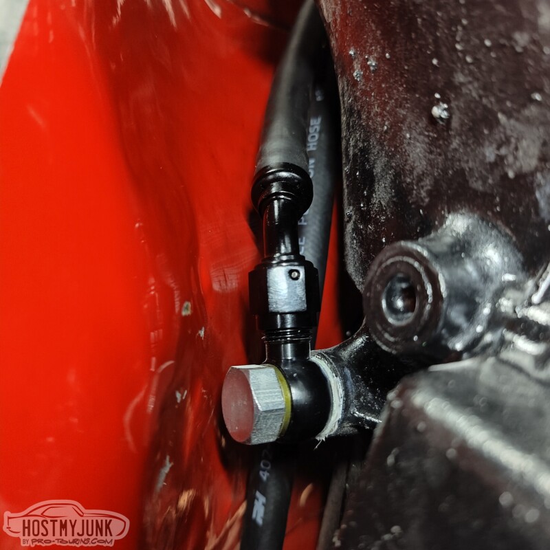
I managed to get the hose end started, but I will probably have to get creative with getting it tight. I think a Crow's foot should get it done.
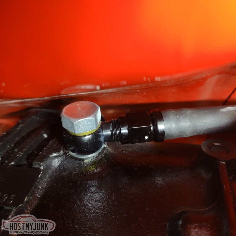
The front port wasn't too bad. I used a 45 degree fitting on this hose. Removing the trans dipstick made access easier.
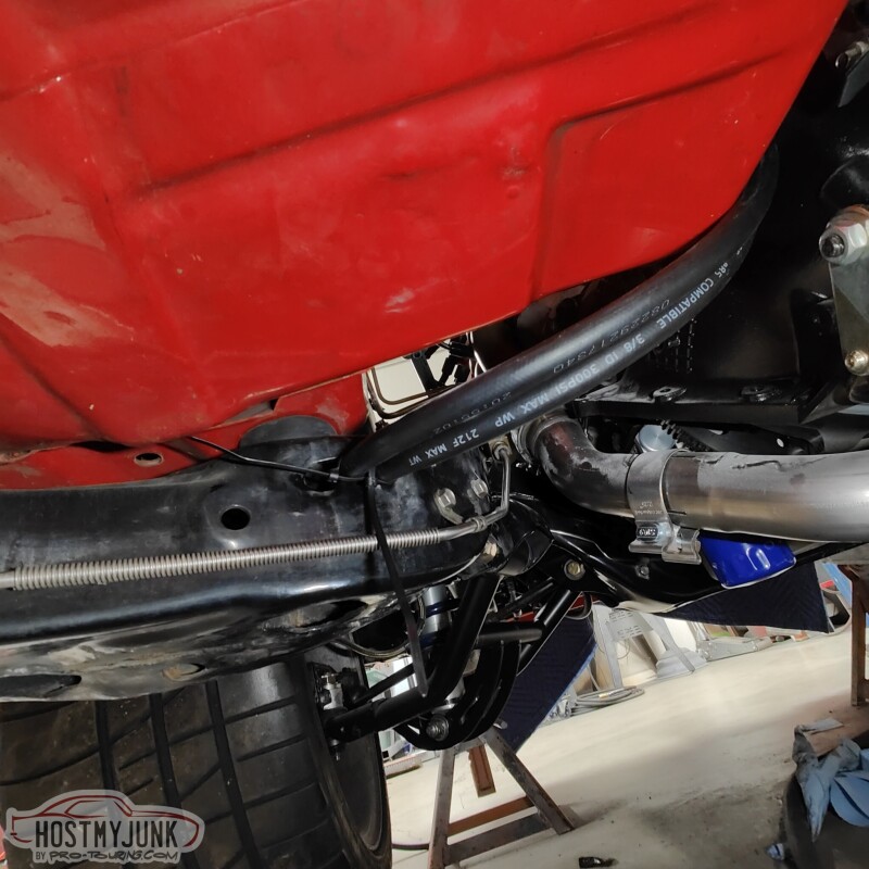
The hoses make a gently sweep over the bell housing area of the transmission, over to the driver's side, where they slip into a slot in the frame. This slot is where the factory hard lines were routed through the frame and out the front crossmember, by the steering box.
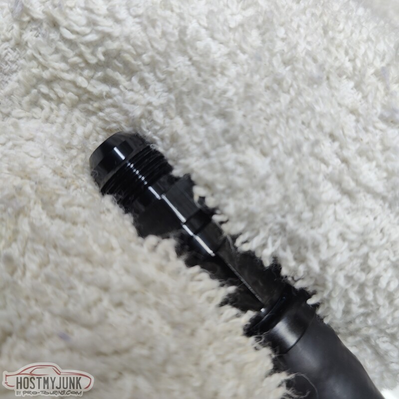
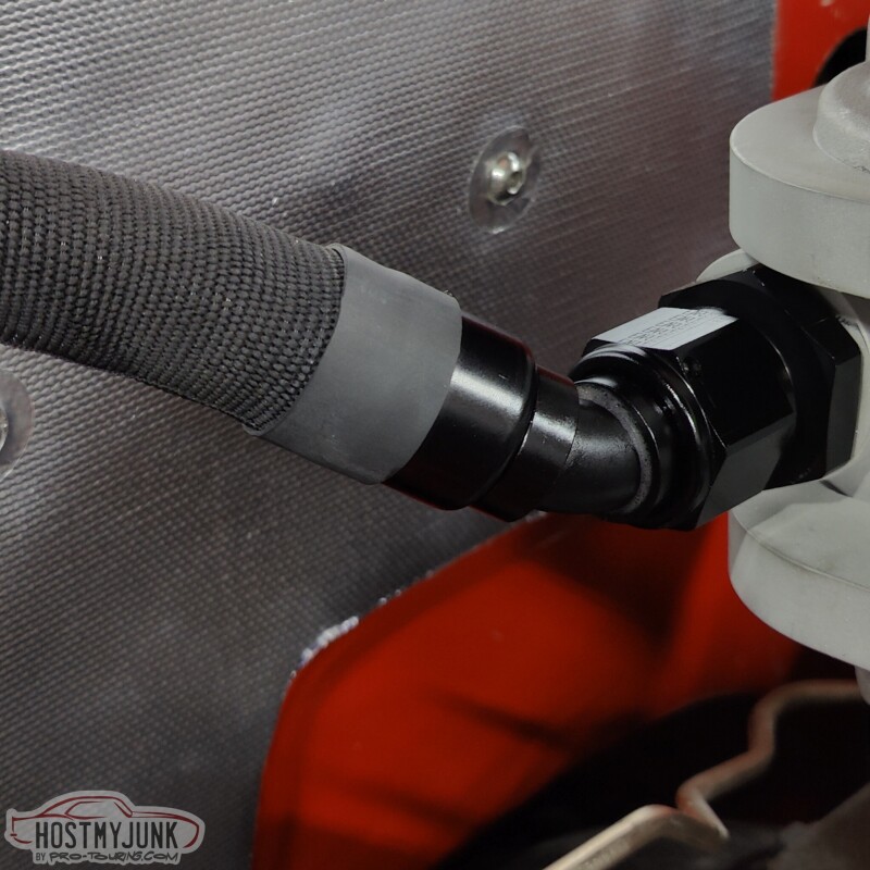
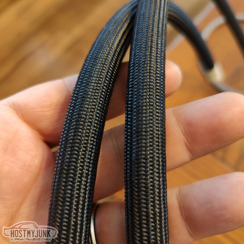
I also experimented with some covering material for the intercooler plumbing. This is a fabric heat shrink material.
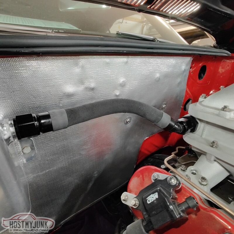
The ends are finished with heat shrink. This is a close-up to show the pattern and texture.
Andrew
Add a union to the fitting and snug it down. This does two things:
1. If using a 45 or 90 degree fitting it keeps the nipple from trying to move around.
2. When putting the fitting in the vise to hold it, it keeps the the nut from crushing and becoming out of round.
This is the rear fitting on the transmission. The picture actually makes it look like there is a lot of clearance, but in reality it is very tight.
I managed to get the hose end started, but I will probably have to get creative with getting it tight. I think a Crow's foot should get it done.
The front port wasn't too bad. I used a 45 degree fitting on this hose. Removing the trans dipstick made access easier.
The hoses make a gently sweep over the bell housing area of the transmission, over to the driver's side, where they slip into a slot in the frame. This slot is where the factory hard lines were routed through the frame and out the front crossmember, by the steering box.
I also experimented with some covering material for the intercooler plumbing. This is a fabric heat shrink material.
The ends are finished with heat shrink. This is a close-up to show the pattern and texture.
Andrew
Thread Starter
Joined: Mar 2003
Posts: 10,604
Likes: 1,881
From: Little Austin
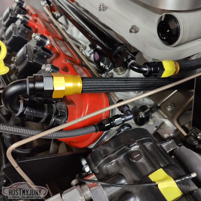
This is Earl's Ultra Pro hose and it is by far the nicest hose I have ever worked with. It is super flexible, light weight, and looks fantastic. Sadly, for some reason, Earl's no longer sells this hose in sizes smaller than AN-10. I had a 6 foot section of AN-6 hose that I had purchased a while back.
So I decided to use it to make some of the needed hoses under the hood. This is the fuel rail crossover that links the two rails together in the front.
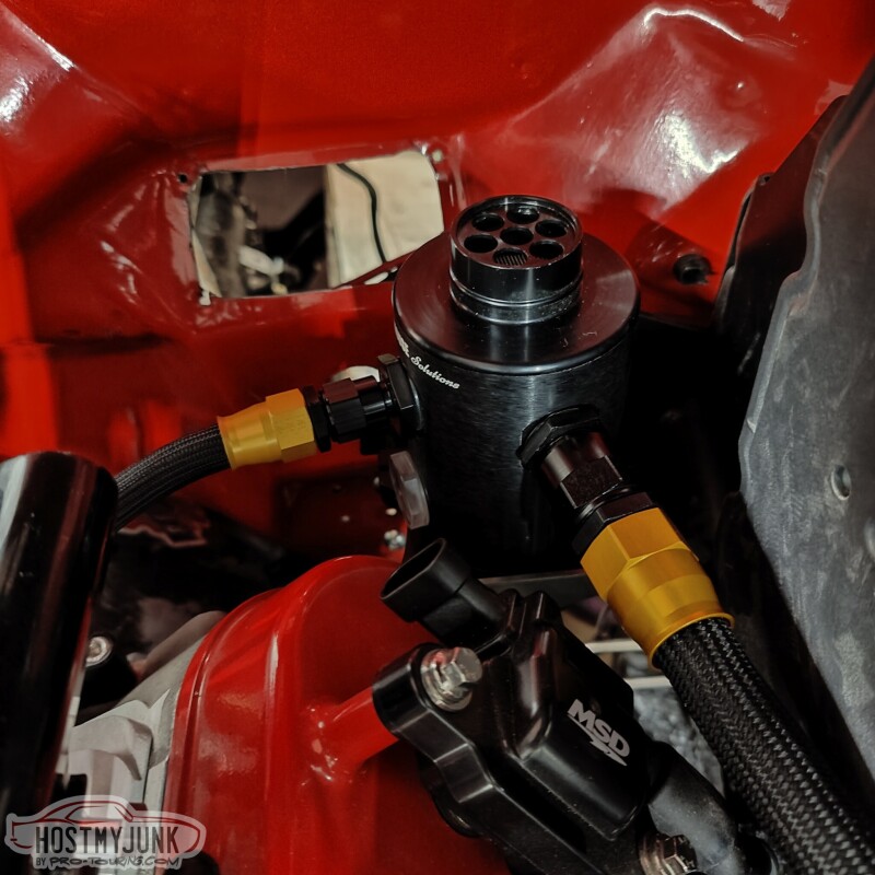
The original plan was to have the Mighty Mouse catch can mounted to the master cylinder mount. However, with the Bosch iBooster in place, that was no longer an option. I got on the MM website and saw they had a basic mount that was designed to bolt to the head.
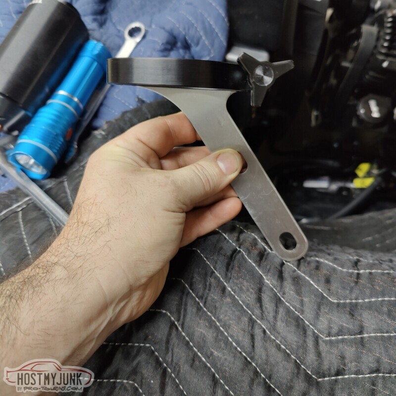
Mounting it to the front of the heads was not an option. The passenger side has the turbo and the driver's side has the alternator. I could have modified this mount to work on the driver's side front, but instead, I chose to flip it around and mount it to the back of the driver's head.
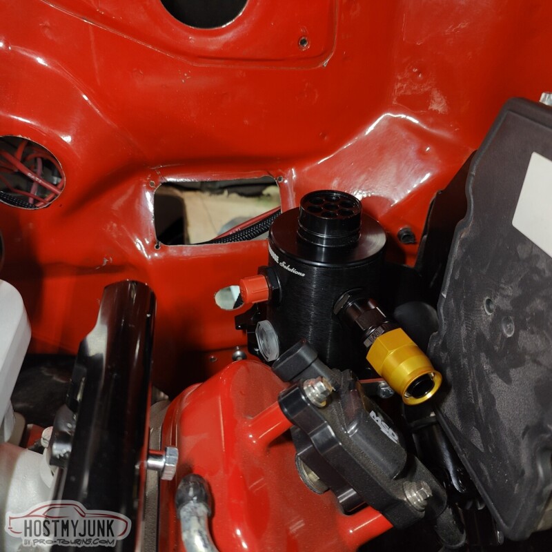
It fit perfectly in the back.
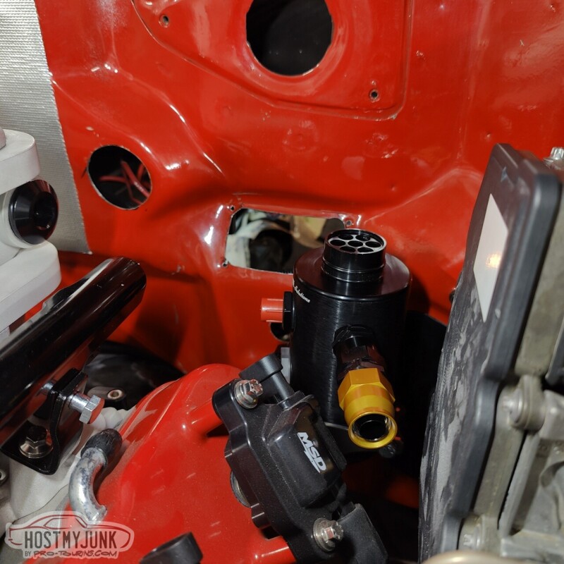
It places it approximately in the same location as the MC mount. There is plenty of clearance all around the can and the mount.
I got this 150 degree fitting and some Earl's Ultra Pro hose in AN-10.
The hose then gently bonds to the catch can.
And in the front, it passes under the plate that holds the boost solenoids.
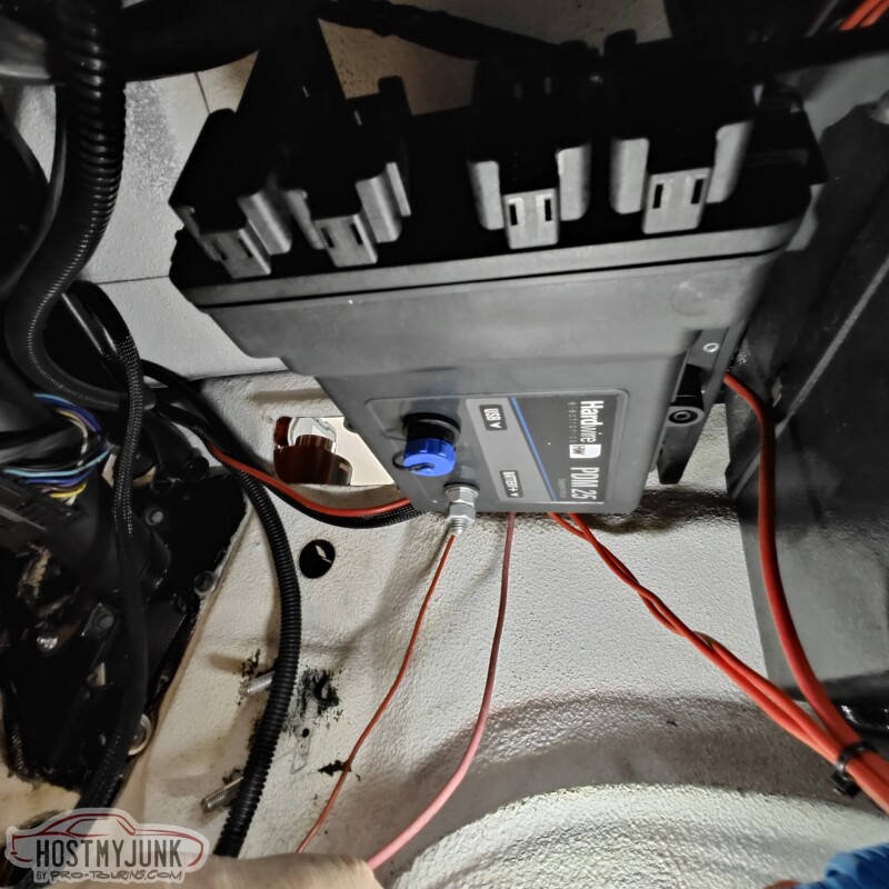
Lastly, this arrived.....
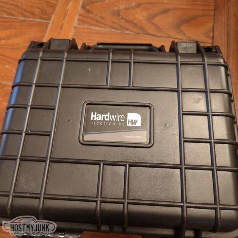
This is the Hardwire Electronics 25 channel PDM.
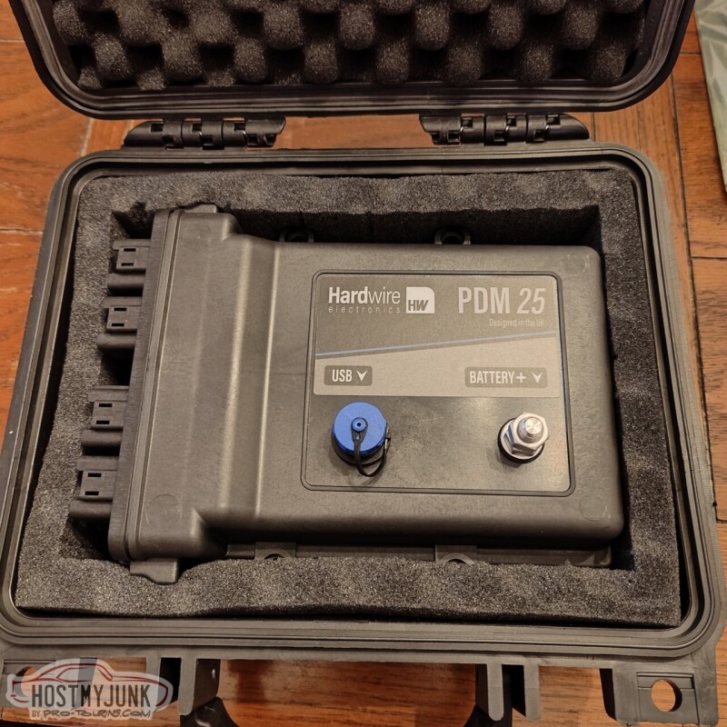
I saw these guys at the PRI show and was very intrigued by the product. This has way more channels than I need for the moment, but I may eventually have it handling the power distribution for the whole car. For now, the original harness will take care of all the interior and exterior lighting and the power windows. The Hardwire PDM will be use for the EFI, AC, and any other system under the dash.
The Hardwire PDM also supports the Holley 3rd Party CAN protocol (AKA the Racepak protocol), so I be able to do some neat things. More to come on that much later when I start on the wiring.
Andrew
So I decided to use it to make some of the needed hoses under the hood. This is the fuel rail crossover that links the two rails together in the front.
The original plan was to have the Mighty Mouse catch can mounted to the master cylinder mount. However, with the Bosch iBooster in place, that was no longer an option. I got on the MM website and saw they had a basic mount that was designed to bolt to the head.
Mounting it to the front of the heads was not an option. The passenger side has the turbo and the driver's side has the alternator. I could have modified this mount to work on the driver's side front, but instead, I chose to flip it around and mount it to the back of the driver's head.
It fit perfectly in the back.
It places it approximately in the same location as the MC mount. There is plenty of clearance all around the can and the mount.
I got this 150 degree fitting and some Earl's Ultra Pro hose in AN-10.
The hose then gently bonds to the catch can.
And in the front, it passes under the plate that holds the boost solenoids.
Lastly, this arrived.....
This is the Hardwire Electronics 25 channel PDM.
I saw these guys at the PRI show and was very intrigued by the product. This has way more channels than I need for the moment, but I may eventually have it handling the power distribution for the whole car. For now, the original harness will take care of all the interior and exterior lighting and the power windows. The Hardwire PDM will be use for the EFI, AC, and any other system under the dash.
The Hardwire PDM also supports the Holley 3rd Party CAN protocol (AKA the Racepak protocol), so I be able to do some neat things. More to come on that much later when I start on the wiring.
Andrew


Thread Starter
Joined: Mar 2003
Posts: 10,604
Likes: 1,881
From: Little Austin
Thread Starter
Joined: Mar 2003
Posts: 10,604
Likes: 1,881
From: Little Austin
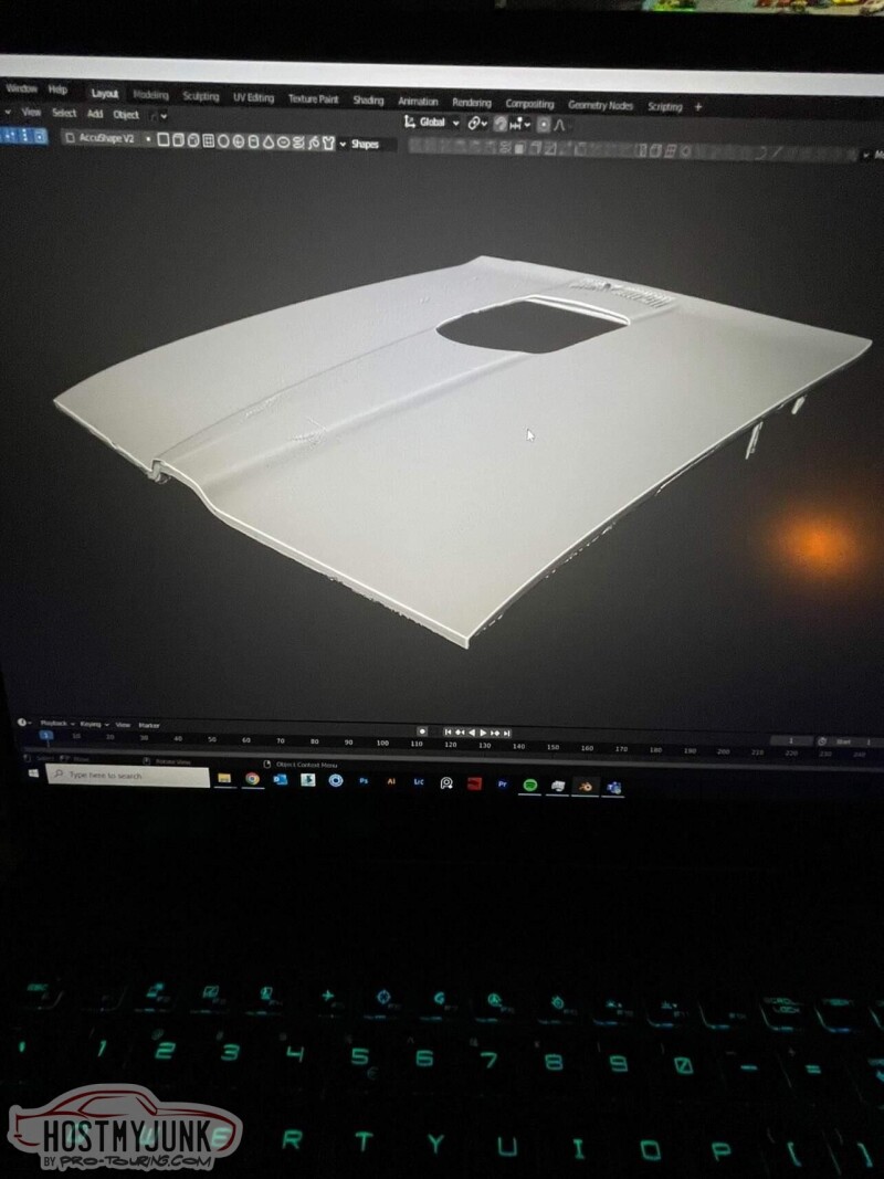
The hood 3D scan turned out really well. I had a chance to work with Kris Horton with the tuning on his Chevelle and he has been working on a rendering of my GTO. He will use the hood scan to refine the rendering and also come up with various ideas about how to deal with the hole in the hood.
Next on the list was finding a suitable location for the Hardwire PDM. My under-dash structure is not like a typical A-body because 20 years ago a frame was built to hold the VA AC unit. Part of this fram structure was also a little shelf where the old Holley Commander 950 ECU used to live.
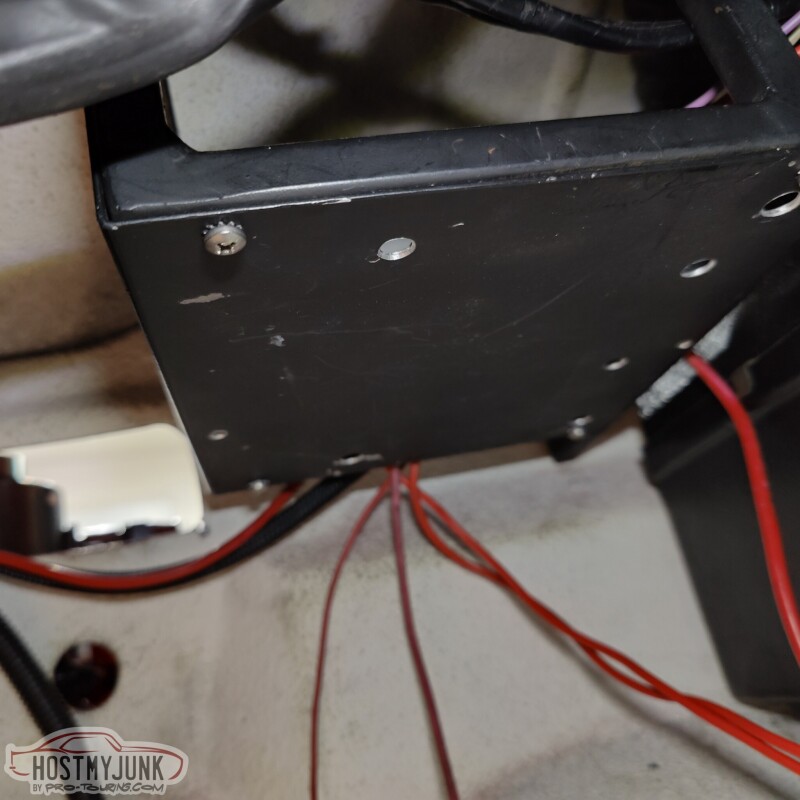
I figured that attaching the PDM under the shelf would be the perfect, central location.
I added some #8 rivnuts to the plate...
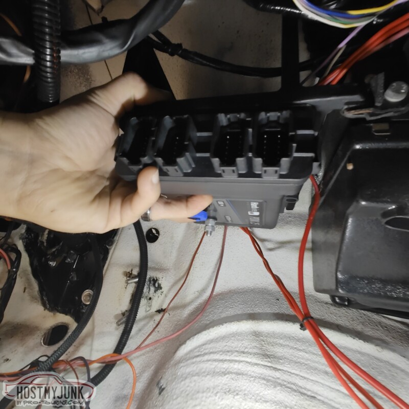
With the PDM bolted down in place...
It is slightly below the level of where the old ash tray used to be, but it is much more inconspicuous than what the pictures indicate. It is tucked up under the dash, while still having all of the connectors easily accessible.
More plumbing....I made the short hose that goes from the catch can to the back of the intake manifold.
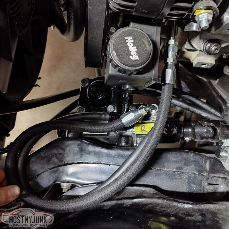
Lastly, I made a short hose for the power steering pressure side.
Andrew
Next on the list was finding a suitable location for the Hardwire PDM. My under-dash structure is not like a typical A-body because 20 years ago a frame was built to hold the VA AC unit. Part of this fram structure was also a little shelf where the old Holley Commander 950 ECU used to live.
I figured that attaching the PDM under the shelf would be the perfect, central location.
I added some #8 rivnuts to the plate...
With the PDM bolted down in place...
It is slightly below the level of where the old ash tray used to be, but it is much more inconspicuous than what the pictures indicate. It is tucked up under the dash, while still having all of the connectors easily accessible.
More plumbing....I made the short hose that goes from the catch can to the back of the intake manifold.
Lastly, I made a short hose for the power steering pressure side.
Andrew

TECH Apprentice

Joined: Apr 2019
Posts: 301
Likes: 129
@02redchevy,
We offer a plethora of self-adhesive heat barrier products with options in our own brand. Feel free to shoot us a PM for any further assistance!
We offer a plethora of self-adhesive heat barrier products with options in our own brand. Feel free to shoot us a PM for any further assistance!

https://www.summitracing.com/parts/dei-050549
Also, if you want to send me some to try out I can hahaha


Thread Starter
Joined: Mar 2003
Posts: 10,604
Likes: 1,881
From: Little Austin
TechFlex makes many different products. The one I used is this:
https://www.wirecare.com/category/he...ric-heavy-duty
Andrew
https://www.wirecare.com/category/he...ric-heavy-duty
Andrew
TECH Apprentice
Joined: Apr 2019
Posts: 301
Likes: 129
TechFlex makes many different products. The one I used is this:
https://www.wirecare.com/category/he...ric-heavy-duty
Andrew
https://www.wirecare.com/category/he...ric-heavy-duty
Andrew
I am half tempted to unwrap my terminator harness and rewrap it in that.
Thread Starter
Joined: Mar 2003
Posts: 10,604
Likes: 1,881
From: Little Austin
Thread Starter
Joined: Mar 2003
Posts: 10,604
Likes: 1,881
From: Little Austin
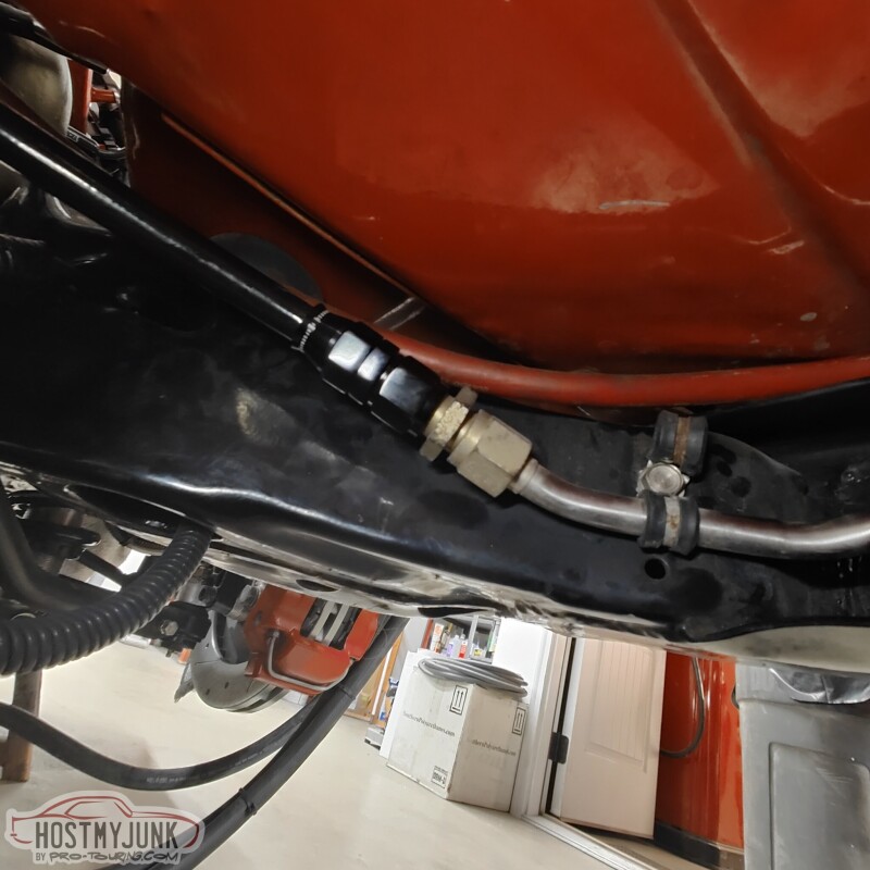
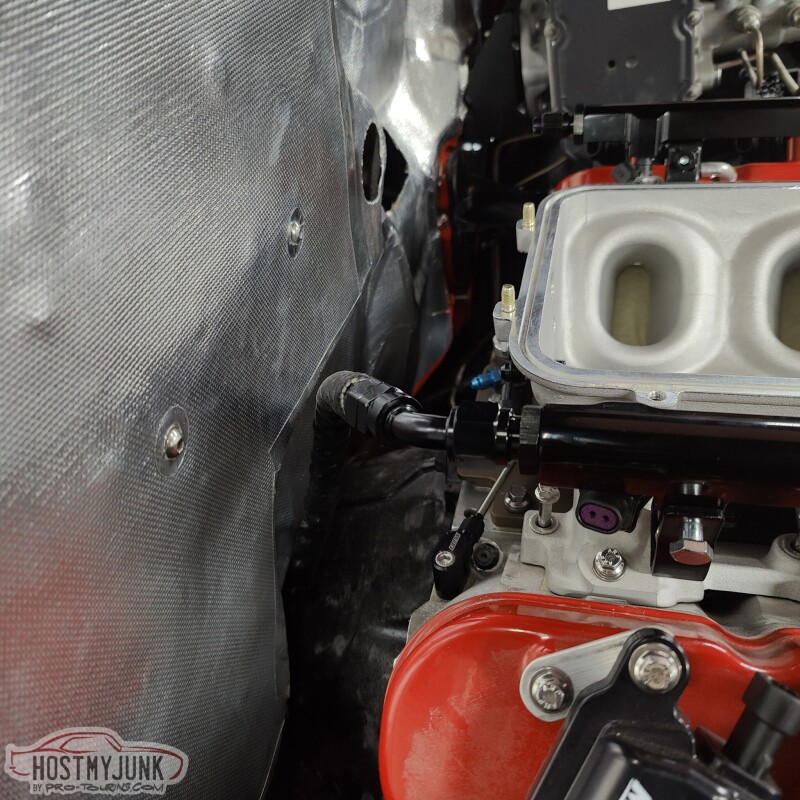
When I originally built the car, twenty years ago, I had the foresight to install a 1/2" stainless fuel hardline that runs from the back, along the frame rail, and exits here at the front of the frame. It already had a AN-8 male fitting on the end.
I have been sourcing some of my plumbing supplies here locally from Star Performance. This PTFE hose is branded under the Red Horse brand of hoses and fittings.
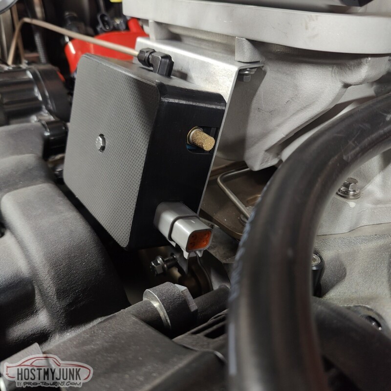
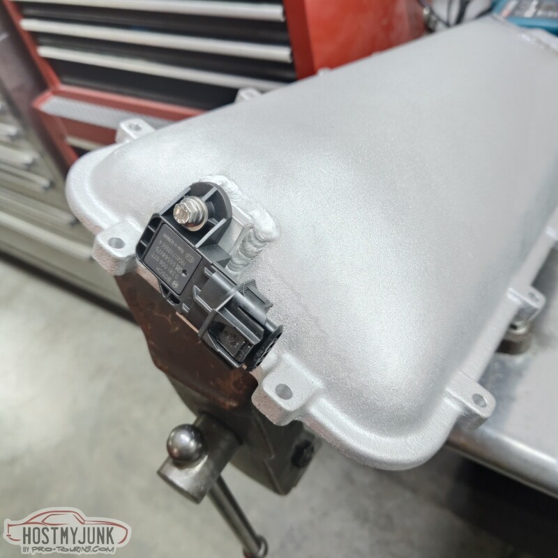
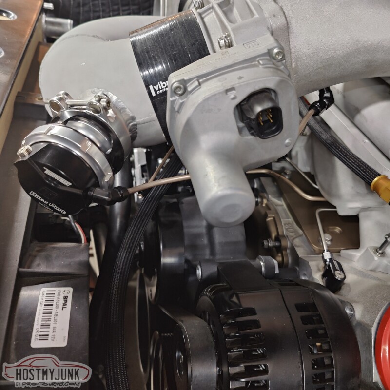
Vic and I also made a little mount for the TMAP sensor that is above the Tick intercooler. This way I can datalog both air temperature and boost pressure above and below the intercooler, so I can see how well it is working.
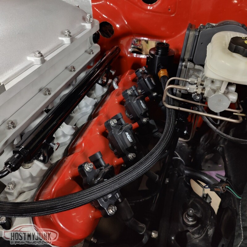
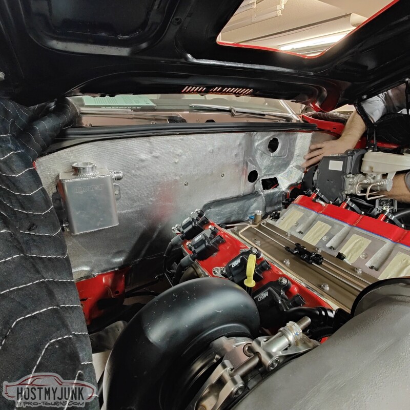
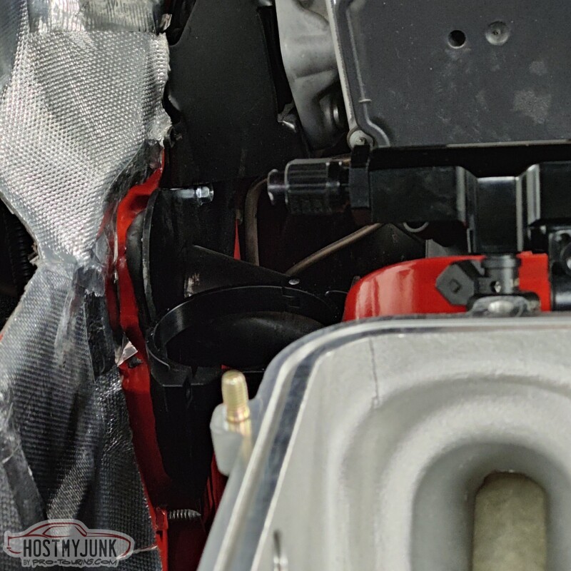
Vic also cut out the rest of the panels to cover the firewall. I really like the overall look. It looks clean and adds a layer of heat insulations.
Back to the fuel system. I was originally going to bring the -8 hose from the frame rail, to the back of the intake and have a Y-bock and 2 -6 hoses to the rails. This was proving to be kind of a pain in the a$$, so I made my life easier...
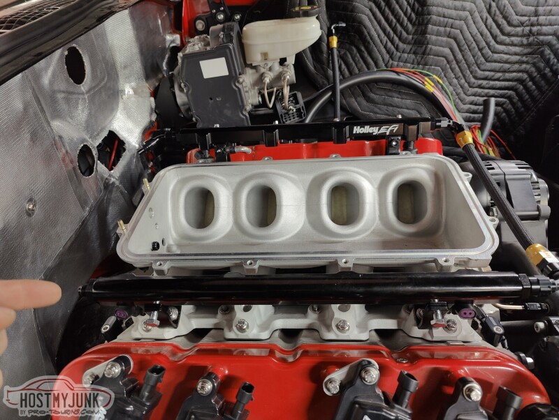
The -8 hose from the frame rail feeds into the passenger side fuel rail.
There is a cross-over hose at the front and the rear of the driver's side fuel rail is capped off.
I also bent up a little NiCopp tube for the blow-off valve.
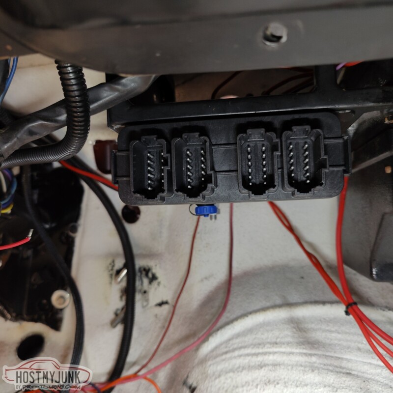
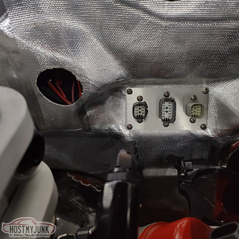
This is the plate that I had made earlier. These connectors will be for the injectors and coil harnesses.
Andrew
I have been sourcing some of my plumbing supplies here locally from Star Performance. This PTFE hose is branded under the Red Horse brand of hoses and fittings.
Vic and I also made a little mount for the TMAP sensor that is above the Tick intercooler. This way I can datalog both air temperature and boost pressure above and below the intercooler, so I can see how well it is working.
Vic also cut out the rest of the panels to cover the firewall. I really like the overall look. It looks clean and adds a layer of heat insulations.
Back to the fuel system. I was originally going to bring the -8 hose from the frame rail, to the back of the intake and have a Y-bock and 2 -6 hoses to the rails. This was proving to be kind of a pain in the a$$, so I made my life easier...
The -8 hose from the frame rail feeds into the passenger side fuel rail.
There is a cross-over hose at the front and the rear of the driver's side fuel rail is capped off.
I also bent up a little NiCopp tube for the blow-off valve.
This is the plate that I had made earlier. These connectors will be for the injectors and coil harnesses.
Andrew
Thread Starter
Joined: Mar 2003
Posts: 10,604
Likes: 1,881
From: Little Austin
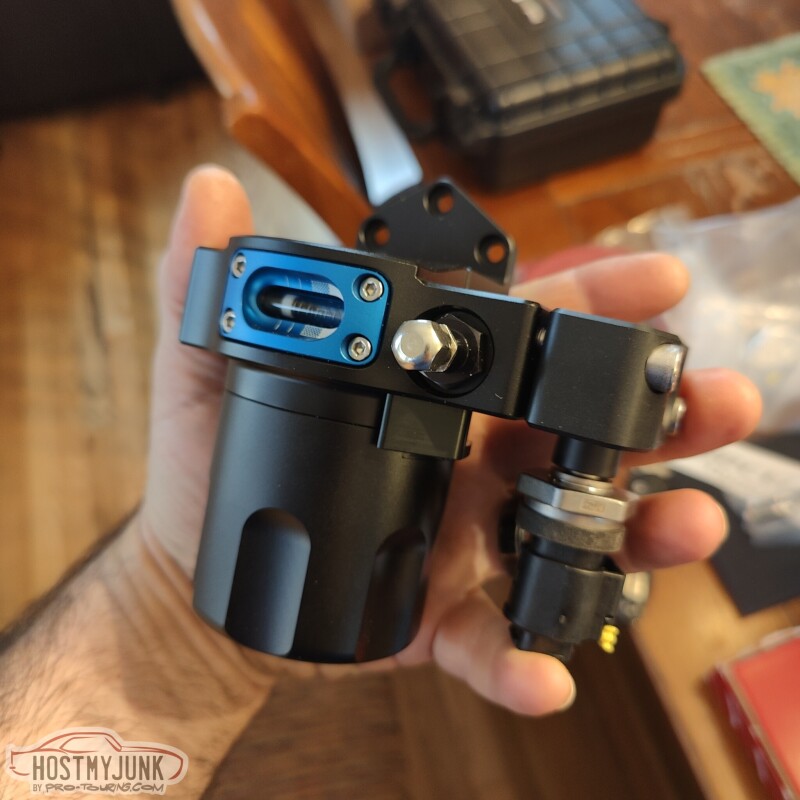
With the fuel plumbing finished up under the hood, it was time to figure out what needed to be done in the back. I recently ordered some wiring supplies from www.milspecwiring.com, and as I browsed their website, I got suckered in by this little piece of jewelry. It is the Injector Dynamics ID750 fuel filter. I got mine with the optional Bosch Motorsports fuel pressure/temp sensor. The little Schrader valve port will be repurposed to plumb the pressure relief valve that was recommended by Carl at Vaporworx.
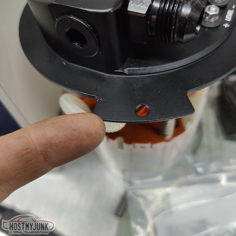
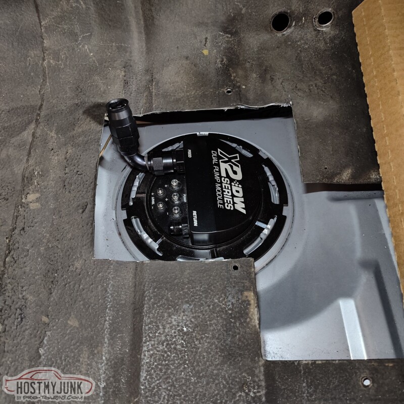
The DeatschWerks 5th Gen Camaro pump module that I am using has this alignment tab that is used in the OEM application to properly clock the pump. Since mine is going into a Rick's RestoMod tank, I did not need this tab, so it was cut off.
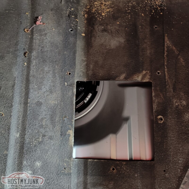
Once the tank was installed in the car, it was obvious that the access hole that was there before was not going to work.
I am also thinking that the fuel filter, flex fuel sensor, and the pressure relief valve will be plumbed inside the trunk. There is just not a lot of room under the car. I know it is "risky" (whatever that means) but that is how I am going to do it.
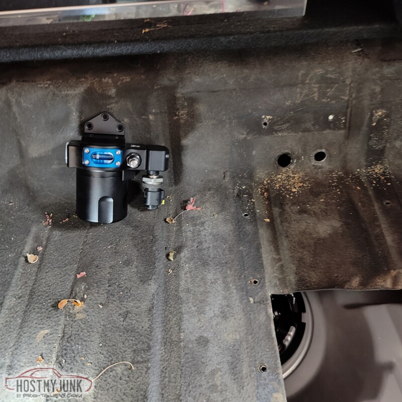
I got the whizzwheelofdeath out and made a new hole in the trunk. All of this will get cleaned up with a nice cover panel.
Andrew
The DeatschWerks 5th Gen Camaro pump module that I am using has this alignment tab that is used in the OEM application to properly clock the pump. Since mine is going into a Rick's RestoMod tank, I did not need this tab, so it was cut off.
Once the tank was installed in the car, it was obvious that the access hole that was there before was not going to work.
I am also thinking that the fuel filter, flex fuel sensor, and the pressure relief valve will be plumbed inside the trunk. There is just not a lot of room under the car. I know it is "risky" (whatever that means) but that is how I am going to do it.
I got the whizzwheelofdeath out and made a new hole in the trunk. All of this will get cleaned up with a nice cover panel.
Andrew
Thread Starter
Joined: Mar 2003
Posts: 10,604
Likes: 1,881
From: Little Austin
I don't know how I feel about this yet, but that's what I got so far.
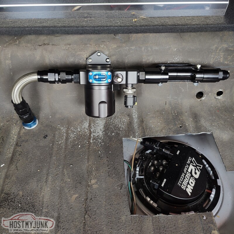
The fuel line comes to of the pump, under the trunk floor, through a bulkhead fitting, then to the fuel filter and the flex fuel sensor holder.
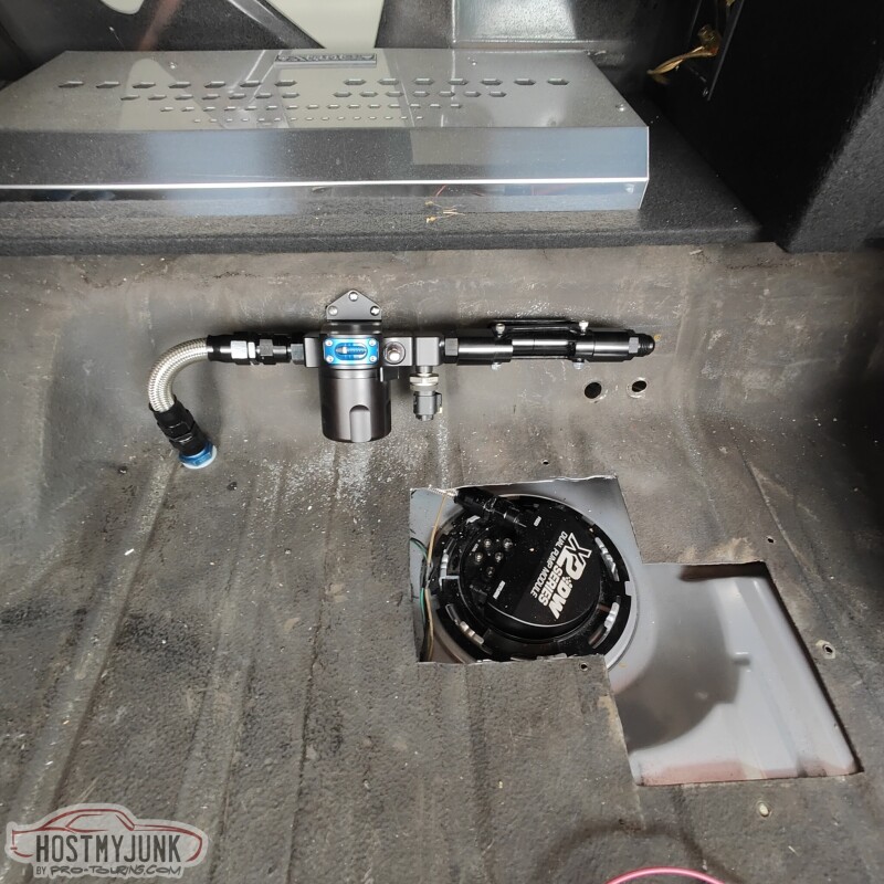
The upside to this arrangement is that servicing the fuel filter, flex fuel sensor, and the wiring would be very simple and easy.
Andrew
The fuel line comes to of the pump, under the trunk floor, through a bulkhead fitting, then to the fuel filter and the flex fuel sensor holder.
The upside to this arrangement is that servicing the fuel filter, flex fuel sensor, and the wiring would be very simple and easy.
Andrew