
First turbo build, 70 GTO...

Thread Starter

Joined: Mar 2003
Posts: 10,604
Likes: 1,881
From: Little Austin
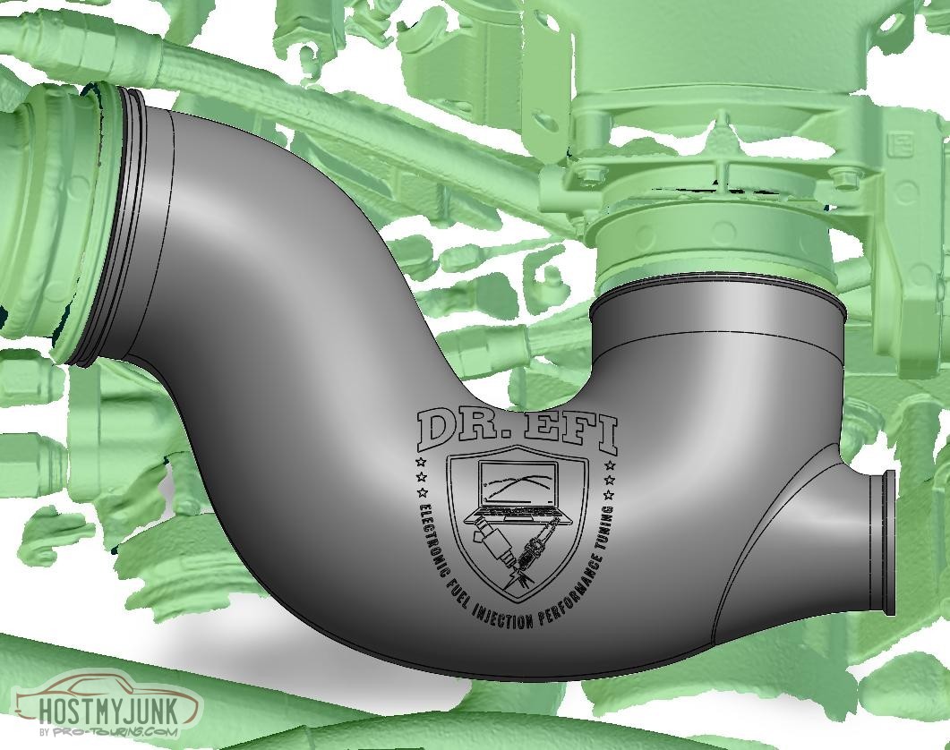
A generous fillet was added around the BOV mount and here is the final part:
I ordered a prototype printed in PLA and it was less than $100 shipped. The aluminum part should come in under $600.
Andrew
I ordered a prototype printed in PLA and it was less than $100 shipped. The aluminum part should come in under $600.
Andrew


Thread Starter
Joined: Mar 2003
Posts: 10,604
Likes: 1,881
From: Little Austin
The reason that I have not cleaned it up yet is because I need to scan the top of the intake fully so that I can have something designed that will hold the shaker scoop to the top of the engine.
Andrew
Thread Starter
Joined: Mar 2003
Posts: 10,604
Likes: 1,881
From: Little Austin
Thread Starter
Joined: Mar 2003
Posts: 10,604
Likes: 1,881
From: Little Austin
Here is the updates design. The BOV location was moved, the logo was moved, and there wall thickness on the little nipple by the compressor exit was increased (not visible).
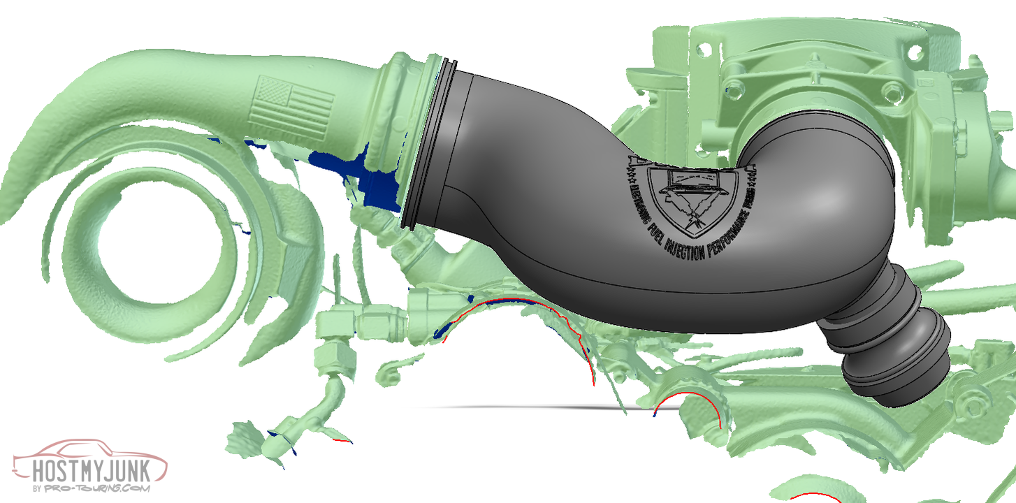
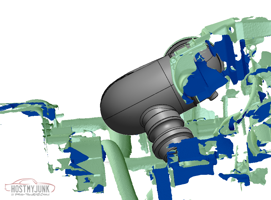
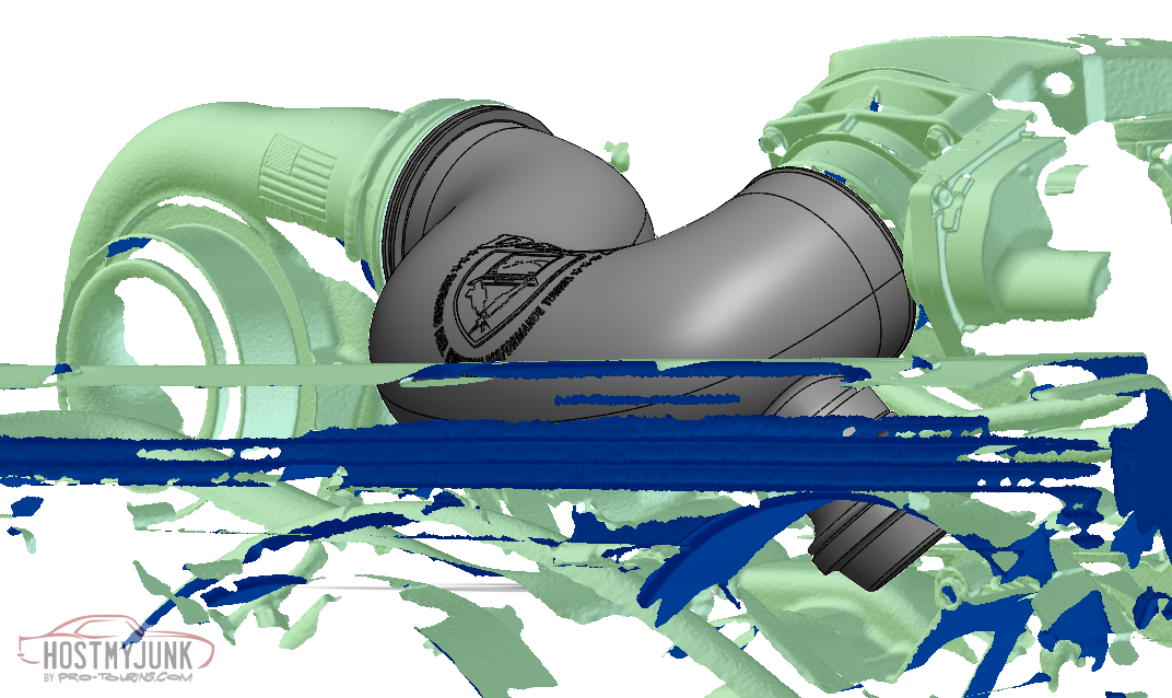
Andrew
Andrew

What was the reason for relocating the BOV?
did you use CFD to determine the second location was better? Seems like you don’t really do anything in a haphazard way. So, there must have been a compelling reason.
did you use CFD to determine the second location was better? Seems like you don’t really do anything in a haphazard way. So, there must have been a compelling reason.
Thread Starter
Joined: Mar 2003
Posts: 10,604
Likes: 1,881
From: Little Austin
Andrew
Thread Starter
Joined: Mar 2003
Posts: 10,604
Likes: 1,881
From: Little Austin
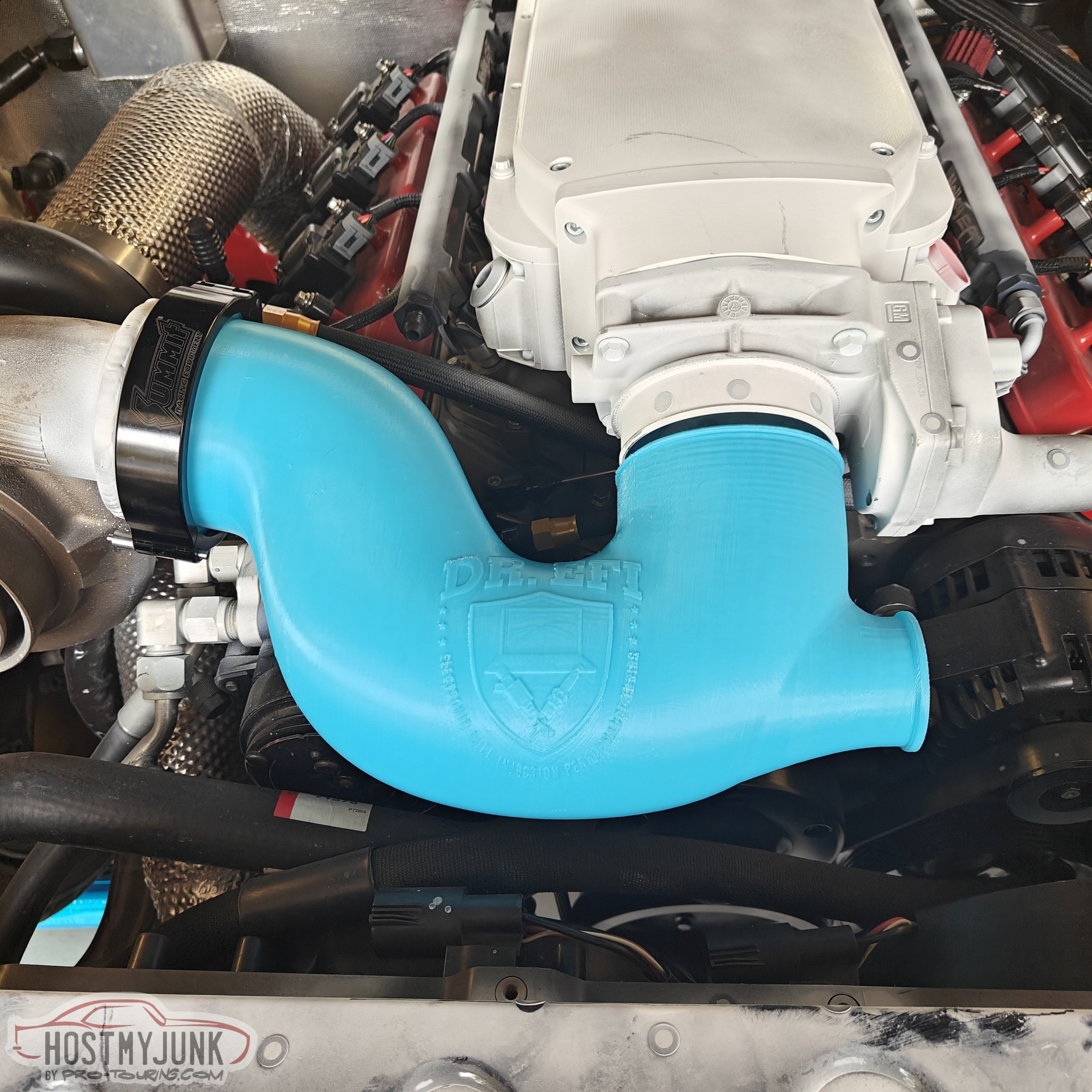
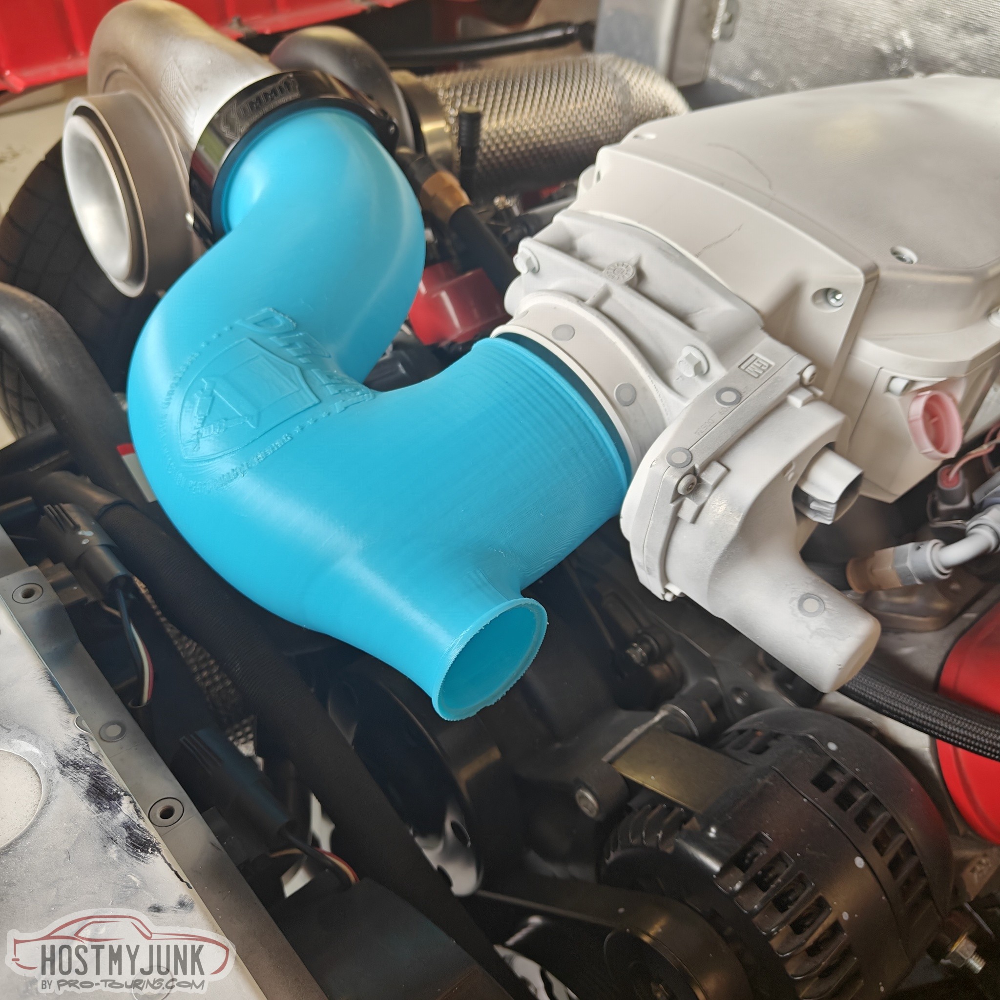
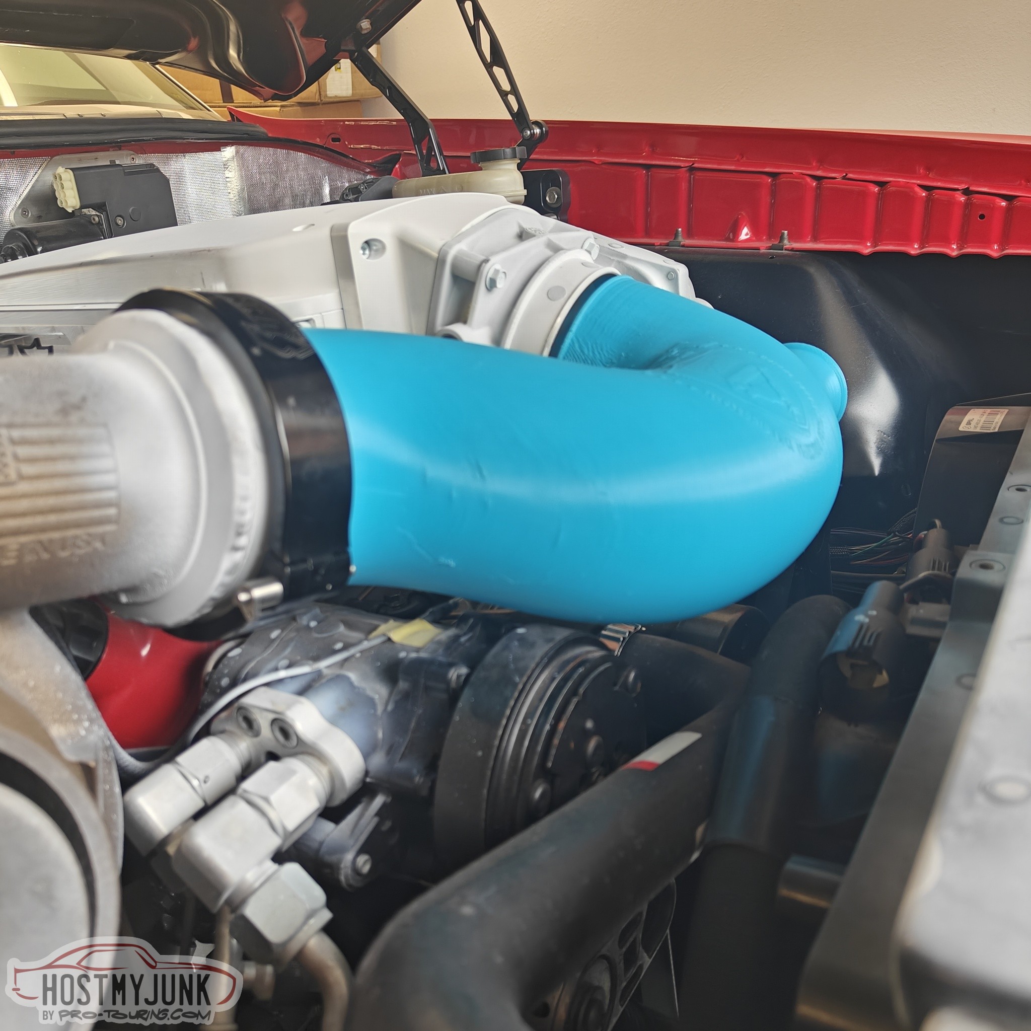
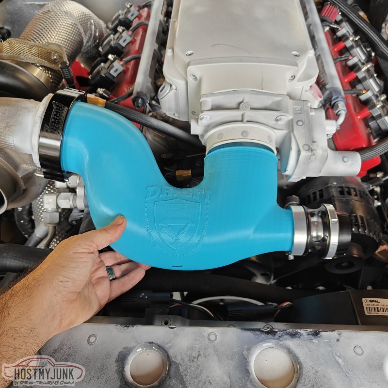
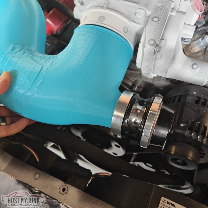
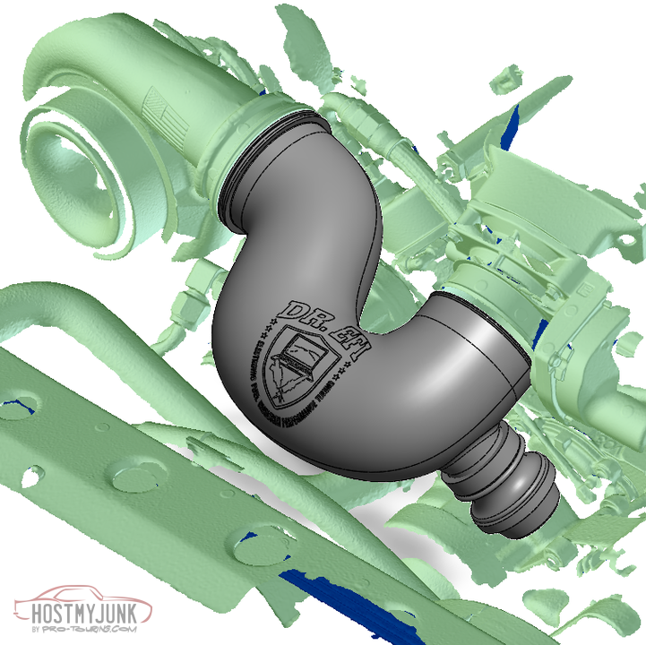
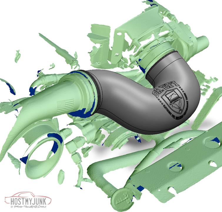
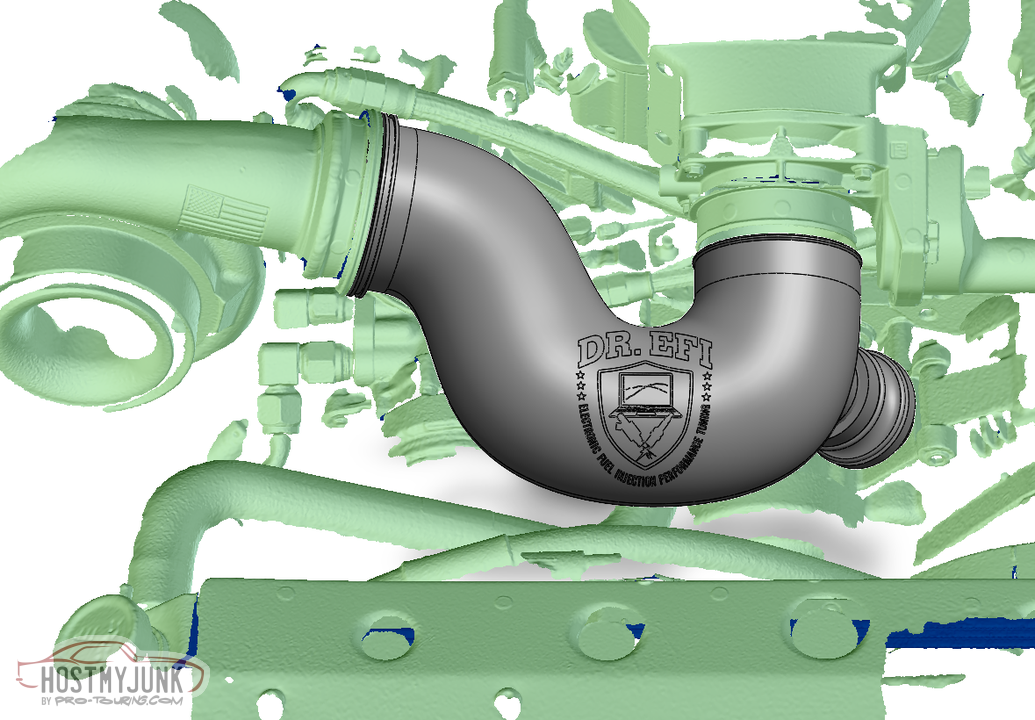
Here is the second prototype printed in carbon reinforced PETG.
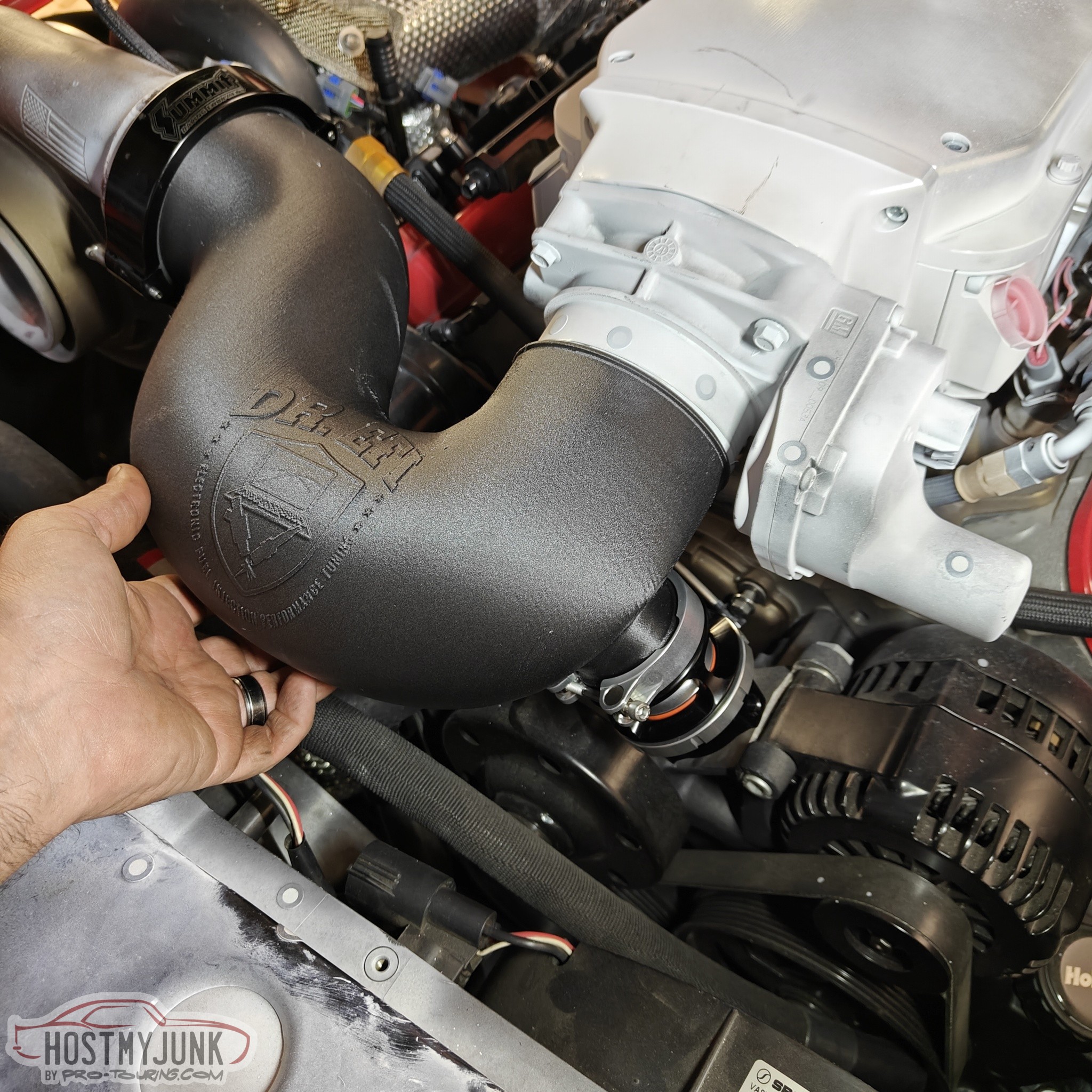
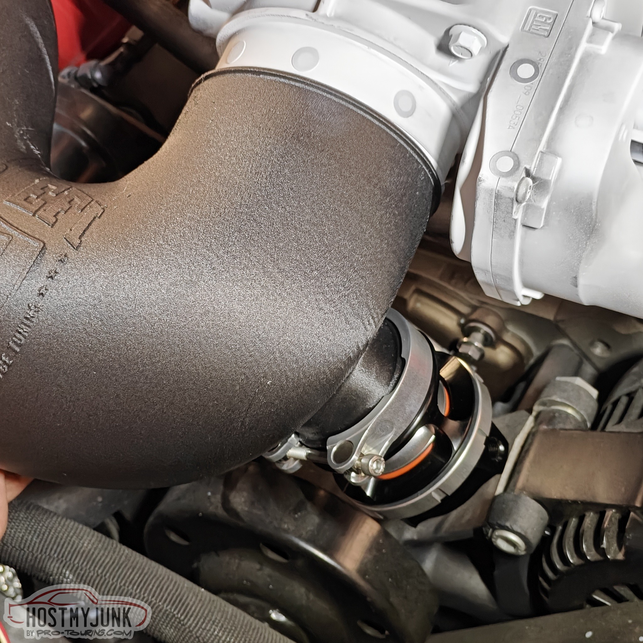
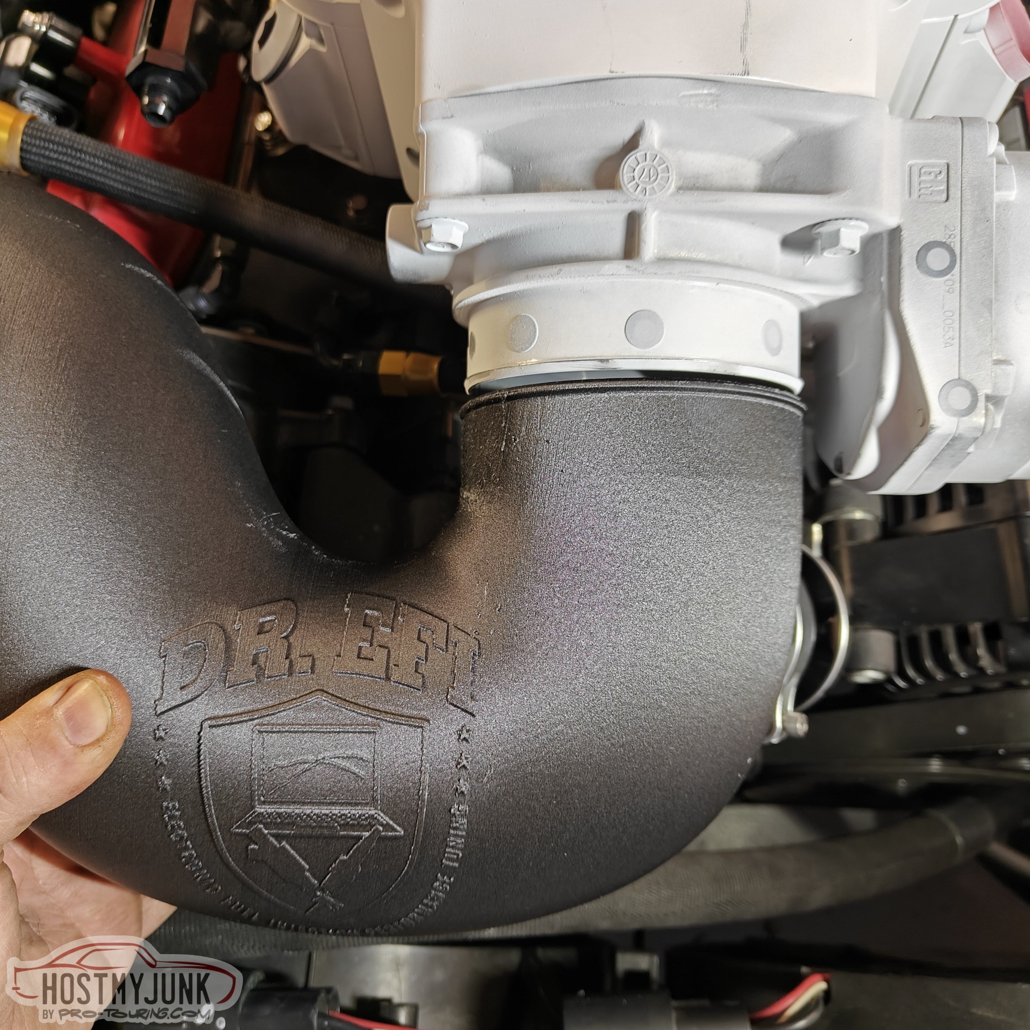
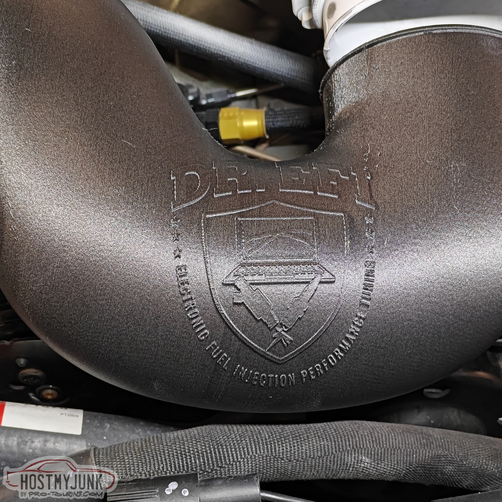
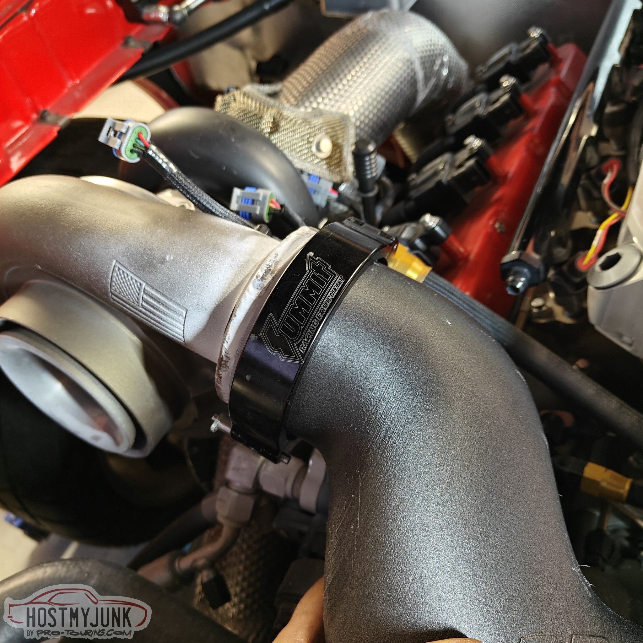
I like the new BOV placement and the slightly repositioned logo.
The next step is to have the final version printed in aluminum.
Andrew
I like the new BOV placement and the slightly repositioned logo.
The next step is to have the final version printed in aluminum.
Andrew
That is so freaking cool Andrew.
Just showed this to my 14-year-old son who's big into 3D printing, he's asking who did the printing for you if you don't mind me asking?
Why not just run the one made?
My son seems to think it'd be plenty strong for what you're doing and shed heat better than aluminum.
Just showed this to my 14-year-old son who's big into 3D printing, he's asking who did the printing for you if you don't mind me asking?
Why not just run the one made?
My son seems to think it'd be plenty strong for what you're doing and shed heat better than aluminum.
Thread Starter
Joined: Mar 2003
Posts: 10,604
Likes: 1,881
From: Little Austin
That is so freaking cool Andrew.
Just showed this to my 14-year-old son who's big into 3D printing, he's asking who did the printing for you if you don't mind me asking?
Why not just run the one made?
My son seems to think it'd be plenty strong for what you're doing and shed heat better than aluminum.
Just showed this to my 14-year-old son who's big into 3D printing, he's asking who did the printing for you if you don't mind me asking?
Why not just run the one made?
My son seems to think it'd be plenty strong for what you're doing and shed heat better than aluminum.
I seriously doubt that the CF PETG would hold up to boost and heat. Keep in mind that the air coming out of the turbo is going to be about 250 degrees F at 20psi, plus all of the ambient heat in the engine bay. I just ordered the aluminum part.
Andrew
Last edited by Project GatTagO; Nov 15, 2024 at 02:21 PM.


I used a broker called CraftCloud.
I seriously doubt that the CF PETG would hold up to boost and heat. Keep in mind that the air coming out of the turbo is going to be about 250 degrees F at 20psi, plus all of the ambient heat in the engine bay. I just ordered the aluminum part.
Andrew
I seriously doubt that the CF PETG would hold up to boost and heat. Keep in mind that the air coming out of the turbo is going to be about 250 degrees F at 20psi, plus all of the ambient heat in the engine bay. I just ordered the aluminum part.
Andrew
edit-- I have seen quite a few strength tests on CF infused filaments, and they are not much if any stronger with CF than without. They mostly seem to just look cooler.
Thread Starter
Joined: Mar 2003
Posts: 10,604
Likes: 1,881
From: Little Austin
PETG would almost certainly fail under those temps and pressure, but PC or nylon would probably hold up fine, and weigh less than aluminum. That being said, I would 100% go with aluminum given the option. I would love to see fluid flow models, but your revised BOV location almost has to be less disruptive to airflow than the original location.
edit-- I have seen quite a few strength tests on CF infused filaments, and they are not much if any stronger with CF than without. They mostly seem to just look cooler.
edit-- I have seen quite a few strength tests on CF infused filaments, and they are not much if any stronger with CF than without. They mostly seem to just look cooler.
If weight was an absolute concern, various methods could be used make this part out of pre-preg carbon fiber, but that would end up costing more than the 3D printed aluminum part.
Andrew

TECH Addict


Joined: Oct 2002
Posts: 2,782
Likes: 95
From: Mefis
Dumb question, how do you deal with expansion?
I'd have to imagine the turbo manifold will grow/shift/move with heat. Probably not much, but it's gotta, right?
Or maybe I have no clue how that stuff works. Either way, it's really cool.
I'd have to imagine the turbo manifold will grow/shift/move with heat. Probably not much, but it's gotta, right?
Or maybe I have no clue how that stuff works. Either way, it's really cool.
Thread Starter
Joined: Mar 2003
Posts: 10,604
Likes: 1,881
From: Little Austin
Andrew
Andrew, this is really looking cool. Thanks for sharing all the intricacies of this build with us.
Did you know Nick Williams makes a DBW throttle body with a dual seal connector as well? While a silicone coupler will work, and certainly be cheaper, the cool factor might increase… if that’s even possible! lol
Did you know Nick Williams makes a DBW throttle body with a dual seal connector as well? While a silicone coupler will work, and certainly be cheaper, the cool factor might increase… if that’s even possible! lol