


Dual Walbro Wiring Install
I wanted to show people exactly how the wiring should be set up when installing dual fuel pumps with relays. I am using a Hobbs switch to kick the second pump on when I get into boost.
I bought a dual relay with wires setup from summit. Its a VPA #80238. I like this setup because it has both relays attached together and a plug that connect them both with wires coming out of it. These relays are 30 AMP SPDT relays.
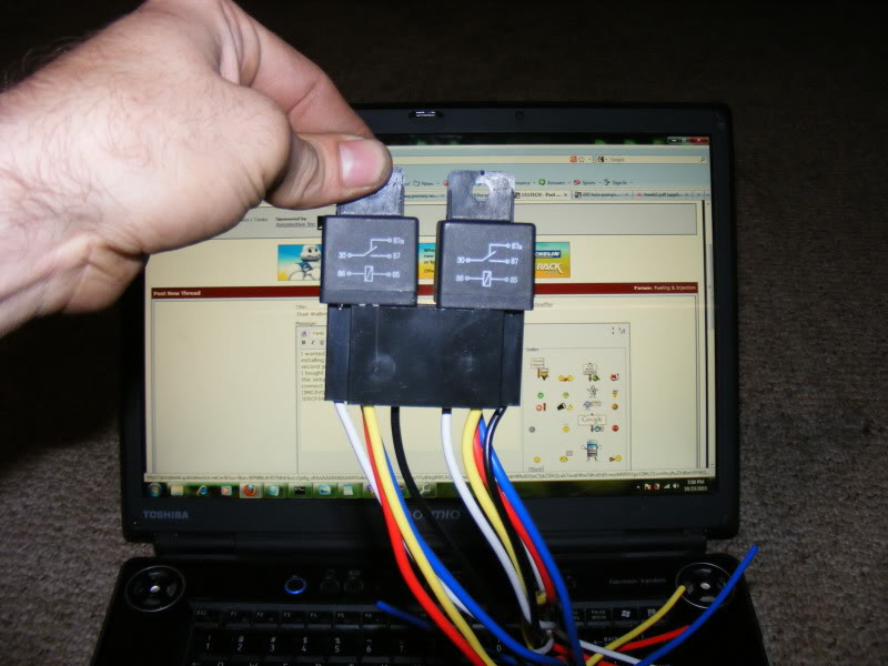
Here is the diagram on my relays in case you have a different relay you can decypher it

On these relays here are the numbers on the relay and the color wire for each number
87 red
87a yellow
85 black
86 white
30 blue
Now here is how you will wire it up.
------------------------------
Left Relay (Primary pump relay)
Black - Ground
White - PCM
Red - Battery
Blue - Pump
------------------------------
Right Relay (Secondary pump relay)
Black - Hobbs Switch
White - PCM
Red - Battery
Blue - Pump
You wont use the yellow wire for anything, you can snip it if you like
Here is a picture of the stock wiring harness that connects to the fuel pump
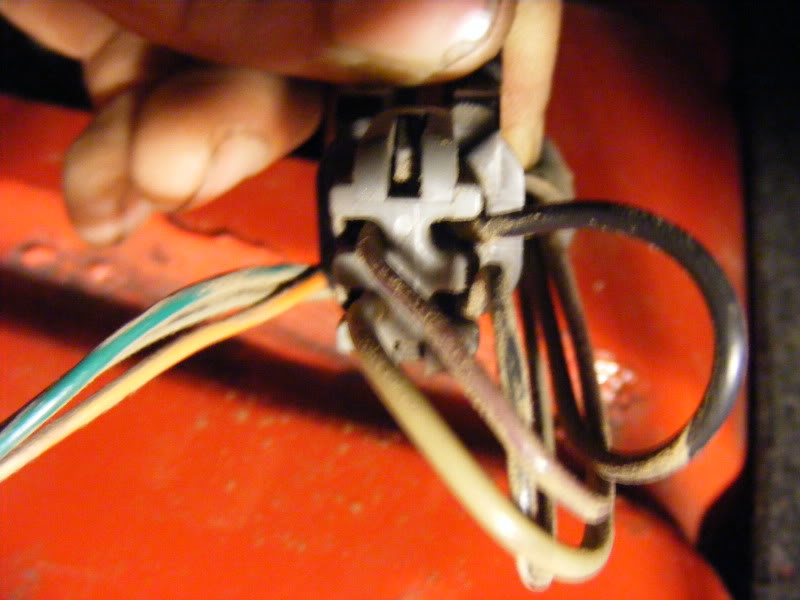
Use the tan wire for the signal wire to energize the relay for your main pump,The black wire was the ground. The other 2 wires are for the fuel level sending unit.
Primary pump wiring--
You will use the tan power wire(From the factory harness) for the signal wire(PCM) and ground your black wire. You will then hook the red wire to your battery power and run the blue wire to your pump. Take your ground wire from your pump and connect it to a good ground somewhere outside the tank.
Secondary pump wiring--
You will use the tan power wire(From the factory harness) for the signal wire(PCM) and connect your black wire to the hobbs switch(This completes the connection to ground when you get into boost). You will then hook the your red wire to your battery power and run the blue wire to your pump. Take your ground wire from your pump and connect it to a good ground somewhere outside the tank.
I would run 10 gauge wire from the battery to your relays, and connect both of your power wires from the relays into your 10 gauge battery power.
I bought a dual relay with wires setup from summit. Its a VPA #80238. I like this setup because it has both relays attached together and a plug that connect them both with wires coming out of it. These relays are 30 AMP SPDT relays.
Here is the diagram on my relays in case you have a different relay you can decypher it
On these relays here are the numbers on the relay and the color wire for each number
87 red
87a yellow
85 black
86 white
30 blue
Now here is how you will wire it up.
------------------------------
Left Relay (Primary pump relay)
Black - Ground
White - PCM
Red - Battery
Blue - Pump
------------------------------
Right Relay (Secondary pump relay)
Black - Hobbs Switch
White - PCM
Red - Battery
Blue - Pump
You wont use the yellow wire for anything, you can snip it if you like
Here is a picture of the stock wiring harness that connects to the fuel pump
Use the tan wire for the signal wire to energize the relay for your main pump,The black wire was the ground. The other 2 wires are for the fuel level sending unit.
Primary pump wiring--
You will use the tan power wire(From the factory harness) for the signal wire(PCM) and ground your black wire. You will then hook the red wire to your battery power and run the blue wire to your pump. Take your ground wire from your pump and connect it to a good ground somewhere outside the tank.
Secondary pump wiring--
You will use the tan power wire(From the factory harness) for the signal wire(PCM) and connect your black wire to the hobbs switch(This completes the connection to ground when you get into boost). You will then hook the your red wire to your battery power and run the blue wire to your pump. Take your ground wire from your pump and connect it to a good ground somewhere outside the tank.
I would run 10 gauge wire from the battery to your relays, and connect both of your power wires from the relays into your 10 gauge battery power.
Last edited by sschoeffler; Oct 23, 2010 at 10:45 PM.
Now what I am wondering is where the heck I can get teflon coated 10awg wire. The 10awg wire I have is PVC coated and from what I hear it will not hold up to the gasoline inside the tank. Also I was testing my hobbs switch and it did not work. So I called up summit racing where I bought it from and come to find out it was not a hobbs switch. It was a Vortech fuel injection pressure switch. so now I am looking for a switch that I can use as my hobbs switch. Does anyone have a part # for that adjustable pressure switch that some folks use? It needs to be a normally open pressure switch, and I would start it out at about 2psi.
Yes the hobbs switch has 2 connectors on it, one goes to ground and 1 goes to the relay. It is normally open, so when the car goes into boost and you add pressure to that hobbs switch it is going to close "complete" the circuit. So just because the hot wire(PCM wire) that is on the relay doesnt mean that relay is energized. It will not energize until that relay is grounded. That relay will ground and complete the circuit when the hobbs switch is activated by boost which will then trigger the second fuel pump.
Trending Topics
Editing this post to explain how it all works.
Here is how a relay works. You will have 2 leads on the relay, see the bottom of the relay I took a picture of number 86 and number 85. Those are your coil wires. When power is applied to those 2 leads the contactors inside of the relay will close and complete a connection between numbers 30 and 87. But that connection is will not conduct any electricity until that coil is energized. Now I have coils 30 and 87 are the hot wires to power the fuel pump. One side is connected to the battery and the other side is connected to the fuel pump. The hot wire is the positive wire.
The hot wire that normally powered the stock fuel pump is going to be the hot wire on the coil side of the relays. Now you can ground the other side of that coil to a the body or you can use the black wire that come from your stock harness doesnt matter. The only reason we are using a relay is so we can beef up the wiring that goes to the primary pump. You could bypass the primary relay if you wanted to just use stock wiring and plug connector. You will however have to splice into that tan wire to activate your secondary fuel pump. These aftermarket pumps really should have a thicker gauge wire going to them than what is wired on the stock harness so thats why I suggest putting a relay on this pump as well.
Now to power the secondary pump. We are going to to connect those 2 leads 86 and 87 which are your coil wires. Take one of them, doesnt matter which one you use, but one of them will be hot. You will use your factory trigger to turn on the fuel pump, Note that just because that wire is hooked up doesnt mean that it is automatically going to be powered. Think of it like this, Touch your tongue to a 9 volt battery, just one post of it, it will not do anything, now do it with the other post, nothing happens, but complete the connection and touch both with your tongue and you will get a zap. The coil on that relay will operate the same way. So anyway you have 1 lead hoked up to your regular fuel pump wire the other end has to be grounded somewhere, wire it to the hobbs switch. Now that hobbs switch(or pressure switch if you will) will not complete the circuit until it senses positive pressure from the boost. Once it receives enough pressure (whatever your pressure switch is rated at to close the circuit) it will close the close the circuit and complete the connection to the ground.
Take the ground wire from both fuel pumps(The pumps themselves) and ground them to the chassis of the car.
So to wrap it all up, when the coils are energized, the connection from your positive power source is completed which is from the battery to the fuel pump itself. Ground both of the pumps to the body. When boost activates the hobbs switch it completes the connection to the second fuel pump and energizes it as well. When you get out of boost the hobbs switch breaks the connection to the ground(That goes to the coil on the relay) and the secondary fuel pump is deactivated.
Stephen
Last edited by sschoeffler; Oct 25, 2010 at 10:45 PM.
LS1 Tech Stories
The Best V8 Stories One Small Block at Time

Gas Monkey Built a 6-Wheel Ferrari Testarossa With a Corvette LT4 Engine
Verdad Gallardo
7 Most Reliable High-Performance Engines GM Has Ever Built
Verdad Gallardo
Amazing '71 Camaro Restomod Is Modern Muscle Car Under the Skin
Verdad Gallardo
6 Common C5 Corvette Failures and What's Involved In Repairing Them
Pouria Savadkouei
Retro Modern Bandit Pontiac Trans AM Comes With Burt Reynolds' Autograph
Verdad Gallardo
Top 10 Greatest Cadillac V Series Performance Models Ever, Ranked
Pouria Savadkouei
Top 10 Most Powerful Chevy Trucks Ever Made!

Hennessey's New Supercharged Silverado ZR2 Has 700 HP
Verdad Gallardo
Coachbuilt N2A Anteros Is an LS2-Powered C6 Corvette In Italian Clothes
Verdad Gallardo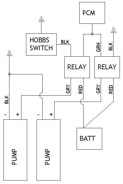
On The Tree
Joined: Jun 2005
Posts: 105
Likes: 0
From: Wyoming
I have an idea. I'm not sure how reliable a hobbs switch is, but I would hate for it to not work. And with dual walbros being as quiet as stock it would be hard to hear if your second pump is running, especially under wot. So i was thinking of mounting a light in a heater vent or something to let you know the switch is sending ground to the pump.
If I've read everything correctly the hobbs sends a ground to the relay. You could just wire up the light to a hot wire under the dash and the ground on the light could be spliced into the wire leading to the back from the hobbs switch. This way the light would turn on when your hobbs switch came on.
What do you guys think? I'm just researching because I'm in the process of piecing together my dual tank setup. I'm only running one pump now with the hotwire kit and it does fine up until I hit 5k in 4th(only gear I don't spin and actually hit 14psi boost). It sputters and I immediately let off, but it will do fine If i floor it again and run up to 6k just fine.
Yes you could do that no problem. I keep an electronic fuel pressure gauge in the pillar. So it is very easy to read and see. Maybe drill an 1/8" hole and put a small red led next to the gauge, that would look real nice and be functional.
Personally I would rather the light come on if the pump WASNT working while it was in boost. Lets say you normally run 50psi fuel pressure. You want that light to come on if you lose your fuel pressure beyond a safe level. You could do that by putting a 45psi fuel pressure switch in the fuel line somewhere and if you drop below 45psi fuel pressure the light would activate. You could even put a buzzer inline and activate the buzzer with the led light.
Personally I would rather the light come on if the pump WASNT working while it was in boost. Lets say you normally run 50psi fuel pressure. You want that light to come on if you lose your fuel pressure beyond a safe level. You could do that by putting a 45psi fuel pressure switch in the fuel line somewhere and if you drop below 45psi fuel pressure the light would activate. You could even put a buzzer inline and activate the buzzer with the led light.


Couple of things -
Why do you need 10gauge teflon going into the tank? For such a short length 14 or even 16 would be fine.(From the top of the bucket into the tank, obviously from the battery to the bucket should be 12)
I hope those relay's are going inside the car in a place that's always going to be dry. Last thing you want are corroded relay terminals giving you some kind of intermittent issues. I think we all know how hard and annoying those can be to diagnose!
No mention of fuses!!!! Wouldn't want someone to wire all that up and not have any fuses between the battery and relay!!
Personally I would save my time and just buy a damn kit from Lonnie.
Why do you need 10gauge teflon going into the tank? For such a short length 14 or even 16 would be fine.(From the top of the bucket into the tank, obviously from the battery to the bucket should be 12)
That simply isn't true. There would be no voltage drop if there is a smaller gauge wire at the end of the harness, especially the very short length of wire needed in the tank.

That simply isn't true. There would be no voltage drop if there is a smaller gauge wire at the end of the harness, especially the very short length of wire needed in the tank.
A large wire at the beginning and a small at the end is the same as a small wire beginning, large at the end or small all over. Wire can only pass X amps before it overheats and melts. If you push Y amps through 10ga wire then try to pass it through 16ga wire rated at X amps, you will melt it. Therefore, X is the max amps you can pass through the circuit because of the smallest wire IE 16 ga in this example
The point Im trying to make is, without the intake wiring, a hotwire kit is just a $50 relay doing the same job of your stock stuff with no benefit
I would use a switch attached to the gas pedal or throttle body so anything over 3/4 throttle setting brings in the second pump.
Adding the switch in for redundancy should a hobbs switch fail (extremely unlikely) isnt a bad idea though