Driveline vibraton found. Coming from rear of transmission.


 01-09-2009, 08:56 PM
#23
What are the chances you have another set of ramps for the rear? If not are the stands as far outboard of the tubes as they can be?? I know when my car is in the air I cannot load the rear susp as much with the jackstands under the frame in the front. Look at your rear tires to body, does it look like it does when it is on the ground? I have a good 3-4 inch diff that my rear sits lower with the car supported by the frame rails. That would equate to a good bit of pinion angle difference with my setup. I am thinking about using a set of stands or even stacking some floor beams to support the car just so I know it is fully loaded and then get it close that way and re-check on the dyno.
 01-09-2009, 10:45 PM
#27
Well like I said earlier, the bushing made a huge difference. I am now convinced my angle finder is not reading right. It is sticking and being stupid. One side works well but the magnetic side must be hosed. I put some more angle into it (now-3* rather than -1*), drove it and the small vibe appears to be further reduced.
I just read on line that 0* angle on a u-joint will vibrate more than one with 2-3*. To quote Captain Jack Sparrow, "Well thats just maddening unhelpful, why cant these things ever be clear".
I am going to Sears tomorrow to get a digital angle finder and check things over again.
http://www.sears.com/shc/s/p_10153_1...48295&sLevel=0
01-10-2009, 09:04 AM
#28

Bill, you are correct with the angle being -1 degree as in the drawing. this should be a great setting, as long as you could put the trans/ds at the same, but opposite angle.
the digi angle finder is a sweet tool, but be sure to use a small carpenters square against the faceplate of the housing to help you get the angle of the pinion. doing this will help you put the two angles on the same plane to ease the confusion of the 90* thing. also be sure to understand which side of zero(level) the angle finder is working on. in this particular situation, it may help to have the car at a angle(maybe nose on the ground, stands under the rearend) to keep the digi level away from the zero number. if you do it with the car close to level, then check the angle and then move the digi level to make the reading zero just for reference. this will help you understand the actual angle in reference to the zero(level) plane.
the digi angle finder is a sweet tool, but be sure to use a small carpenters square against the faceplate of the housing to help you get the angle of the pinion. doing this will help you put the two angles on the same plane to ease the confusion of the 90* thing. also be sure to understand which side of zero(level) the angle finder is working on. in this particular situation, it may help to have the car at a angle(maybe nose on the ground, stands under the rearend) to keep the digi level away from the zero number. if you do it with the car close to level, then check the angle and then move the digi level to make the reading zero just for reference. this will help you understand the actual angle in reference to the zero(level) plane.
01-10-2009, 09:40 AM
#29
Eric, thanks for chiming in.
By referencing this diagram again:
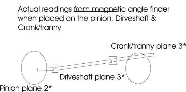
I cant get the opposite 2* angle on the front of the DS connecting to the tranny without somehow lowering the motor. I already have a 1/2" spacer between the tranny crossmember and the tranny mount effectively raising th back of the tranny up 1/2". Right now the rubber stopper on top of the tranny is nearly touching the tunnel. I might be able to remove that stopper and get another 1/4" spacer in there which might get that angle closer to 2 like it should be.
It seems like with the lower pinion position on the 9" compared to the more centered 10 bolt, I need to make these rear tranny height adjustments to get that near perfect driveline angle.
Seems if I lowered the rear of the tranny or used the factory height (no spacers) then the angles would get worse.
It really seems to me that the 9" needs a little more creativity to dial the angle in compared to the 10 bolt.
Do you agree with this or am I *** backwards?
By referencing this diagram again:
I cant get the opposite 2* angle on the front of the DS connecting to the tranny without somehow lowering the motor. I already have a 1/2" spacer between the tranny crossmember and the tranny mount effectively raising th back of the tranny up 1/2". Right now the rubber stopper on top of the tranny is nearly touching the tunnel. I might be able to remove that stopper and get another 1/4" spacer in there which might get that angle closer to 2 like it should be.
It seems like with the lower pinion position on the 9" compared to the more centered 10 bolt, I need to make these rear tranny height adjustments to get that near perfect driveline angle.
Seems if I lowered the rear of the tranny or used the factory height (no spacers) then the angles would get worse.
It really seems to me that the 9" needs a little more creativity to dial the angle in compared to the 10 bolt.
Do you agree with this or am I *** backwards?
Last edited by wrd1972; 01-10-2009 at 09:48 AM.
01-10-2009, 10:27 AM
#30
you are dead on the money... this is actually one of the big reasons why Strange Engineering has never produced a 82-02 f-body bolt-in rearend. the only other way you may help the situation is to alter your rearend ride height... then other things start to happen. lol! sounds like you are finally getting a hold of the entire situation. i have to pat t you on the back for your patience and will to figure it out. most people would have given up!
for others out there... there's way more to the way the *driveline* works. its not just pinion angle. what do you guys with lowering springs think happens to the driveshaft angles? damage travels.
for others out there... there's way more to the way the *driveline* works. its not just pinion angle. what do you guys with lowering springs think happens to the driveshaft angles? damage travels.
01-10-2009, 04:46 PM
#31
I just talked with my buddy today that does this stuff for a living on these cars and he said that with the trans in the stock location, take the digital angle finder to the back of the dshaft and then the front and try to split the diff. Also said the PINION should be pointing down (negative) around negative 1. He said this has never given him a problem. I saw him do this today with a moser 9 inch.
Last edited by 03 BUSA; 01-10-2009 at 05:57 PM.
01-10-2009, 04:57 PM
#32
I just talked with my buddy today that does this stuff for a living on these cars and he said that with the trans in the stock location, take the digital angle finder to the front side of the dshaft and then the front and try to split the diff. Also said the PINION should be pointing down (negative) around negative 1. He said this has never given him a problem. I saw him do this today with a moser 9 inch.
01-10-2009, 05:57 PM
#33
Yes sorry. Put it flat on the rear of the shaft and record number all the way back by the weld. Then do the same thing at the front. Try to split that number. Also he said that you need some working angle as the u-joints are designed to work that way.
01-10-2009, 06:38 PM
#34
It appears I have four options:
1. +2* pinion angle with Pinion & tranny/crank parallel.
2. 0* pinion angle with drive line from crank to pinion straight as an arrow.
3. -1* pinion angle with driveshaft to tranny 0*.
4. -2* pinion angle with driveshaft to tranny +.5*.
As you can see, none of these are perfect, but there has to be some compromise.

What would you guys do?
Last edited by wrd1972; 01-12-2009 at 11:12 AM.
01-10-2009, 07:05 PM
#36
No, the tranny is still jacked up 3/4". I am convinced that raising it up leads to more desirable angles. Going back to stock they get more ugly. I think the diagram illustrates this. Maybe I am wrong, I will pull the spacers to be sure. The digital tool may lead to a different result than with the old tool.
Last edited by wrd1972; 01-10-2009 at 07:13 PM.
01-10-2009, 07:22 PM
#37
I just did some searching and found this from Madman. It makes alot of sense. Just set the pinion and not worry about anything else. Then fine tune from there.
https://ls1tech.com/forums/drag-raci...ion-angle.html
https://ls1tech.com/forums/drag-raci...ion-angle.html
01-10-2009, 07:37 PM
#38
I just did some searching and found this from Madman. It makes alot of sense. Just set the pinion and not worry about anything else. Then fine tune from there.
https://ls1tech.com/forums/drag-raci...ion-angle.html
https://ls1tech.com/forums/drag-raci...ion-angle.html
Set the pinion angle in relation to the ground. The driveshaft is irrelevant. Set your angle finder on the pinion yoke. Set it 2 to 3 degrees down.
I will give it a shot.
I hate geometry.
 01-10-2009, 07:42 PM
#39
I would say to start around 2 cause that was for a car that was a drag car only so he is going to launch pretty hard. But this is what I have been looking for just let us know what the PINION angle should be not the other angles. The pinion angle is just that the angle that the rear pinion is in.
01-10-2009, 08:27 PM
#40
Okay I pulled the 3/4 spacer out so the tranny went back to stock height. I was correct, it makes things worse so I will put the 3/4 spacer back in for further testing.
For comparison purposes, without the spacer, the pinion and the tranny/crank being parallel, the pinion angle was +3.3*. With the spacer, the PA was +2.0*. Obviously I am not going to run either of these, I was trying to determine if raising the tranny up 3/4" was helping or hurting.
It appears I have four options sing the 3/4" spacer:
1. +2* pinion angle with Pinion & tranny/crank parallel.
2. 0* pinion angle with drive line from crank to pinion straight as an arrow.
3. -1* pinion angle with driveshaft to tranny 0*.
4. -2* pinion angle with driveshaft to tranny +.5*.
I will try option 4 and then 3 tomorrow on the road and see what happens.
Last edited by wrd1972; 01-12-2009 at 11:13 AM.