When you click on links to various merchants on this site and make a purchase, this can result in this site earning a commission. Affiliate programs and affiliations include, but are not limited to, the eBay Partner Network.
Yes, correct. I just merely wanted to see if how I plumbed this and if the orificed PCV valve was most ideal/efficient. I�ve been out of the LS game for a while. Last catch can I installed was on my old 99 Silverado.
Didn�t really say anything. I went off routing on my old truck.
Well stock configuration on my car was a hose from the driver side valve cover that tied into the rear facing port on the passenger valve cover and then the hose ran along the top of the passenger cylinder head and connected to the port on the intake manifold behind the throttle body.
This is what is called as the dirty side of the PCV system. The fresh side was a hose from the front facing port on the passenger valve cover to the port on the throttle body and if no port was there then into the air lid or bellow between the MAF and the TB. If installing a sealed catch can just connect it up as mentioned above but instead of the hose going into the intake manifold run it to the inlet side of the catch can and then the outlet side to the intake manifold.
I need to clarify this as this is not only my first LS type engine but I got it without any hoses etc and having read all the posts I'm still unsure of the best way for my install.
I have the later LS6 valley cover with built in PCV
And LS6 intake
5.3 Truck valve covers (which have on 1 hose connection on each)
5.3 TB.
Engine is 5.3 NA.
I also have a twin catch can.
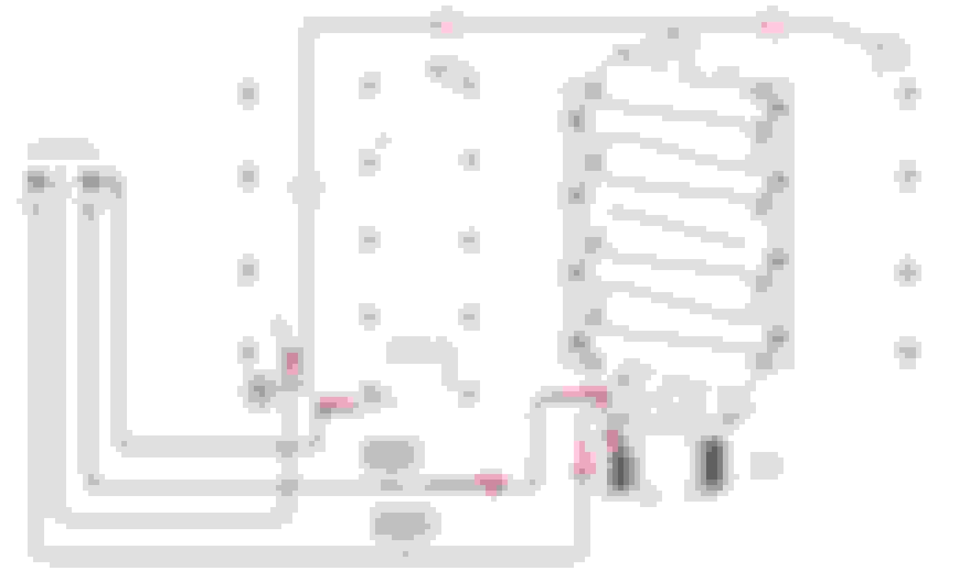
So do I do as follows:
Clean side
Connect Intake connection to inlet on Clean side air catch can then outlet to both Valve covers (to supply fresh air into valve covers and hence crankcase)
Dirty side
Connect Valley cover outlet to inlet on Dirty side catch can then outlet to TB connection
Does this sound right?
Like this...?
Last edited by TableLeg; Apr 26, 2018 at 03:41 AM.
Reason: Image added.
That looks fine to me, but if I were doing it myself, I would simplify it a bit by capping the DS valve cover port and just using the PS inlet. The only restriction in the system is the orifice hole in the valley port, so having two inlets isn't really benefiting.
That looks fine to me, but if I were doing it myself, I would simplify it a bit by capping the DS valve cover port and just using the PS inlet. The only restriction in the system is the orifice hole in the valley port, so having two inlets isn't really benefiting.
Many thanks for the reply. I'll do as you suggest.
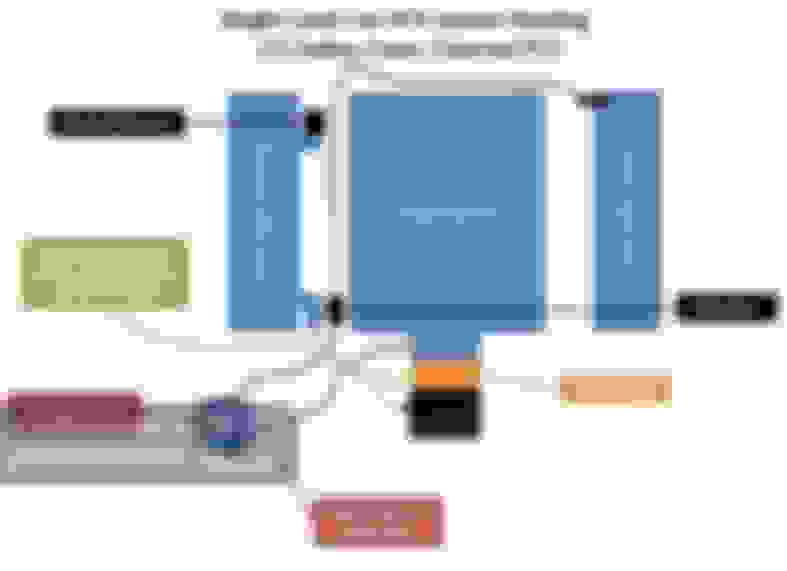
Here is how I recommend connecting your PCV system based on the information provided. Keep in mind that a catch can will not fix mechanical issues. If the engine is too loose, burning oil, etc, a catch can will do nothing to help these conditions.
[IMG]http://www.andersonperformance.net/LS2 Single PCV NA.jpg
9 years later. I just found this thread. I have my catch can set up exactly like this. The only difference is my check valve is the opposite direction.
I thought suction comes from the TB. pulling through both valve covers. dirty goes in from the valley cover port. Ill upload a pic and thats probably why my can doesnt get much action. The intake stays decent from oil residue but Ill swap it around when I get back to the car next week.
Last edited by ssdungeon; Jul 31, 2018 at 10:19 PM.
There is no use for a check valve on a naturally-aspirated setup however all PCV systems require a PCV valve or orifice to regulate intake manifold application to the crankcase.
*further- it is extremely dangerous to follow some online-found schematic vs. the one provided by the manufacturer. accidental error on the engine ventilation strategy can shorten engine life or cause immediate damage.
-if your catch can did not come with info on how to hook it up, it is probably not the best investment.
Last edited by MIGHTYMOUSE; Aug 1, 2018 at 09:32 AM.
There is no use for a check valve on a naturally-aspirated setup however all PCV systems require a PCV valve or orifice to regulate intake manifold application to the crankcase.
*further- it is extremely dangerous to follow some online-found schematic vs. the one provided by the manufacturer. accidental error on the engine ventilation strategy can shorten engine life or cause immediate damage.
-if your catch can did not come with info on how to hook it up, it is probably not the best investment.
Thanks MM for the response. Followed your car for a long time the old car you had.
The thing is there are so many LS setups out here that most cans don't have a diagram for each variation. For instance with or without the LS6 valley cover. Some valve covers have dual ports on the passenger side as pictured and some don't. No one supplies diagrams for all of the possibilities. So we come here . My can is one I made with baffles and all, a check valve is also under the breather to keep unmetered air from coming in but will allow air out if its enough pressure. I have another one on the bench now smaller in size and built a lot better. I like it when I do it myself.
One last question though if I removed the check valve all together. Would that make this routing righteous?
i know it seems reasonable, but because i deal with the repercussions of it every day, i am here to say again that 'sharing' ventilation strategies across all of the catch can variants around is dangerous at the least. if the hook up is not obviously detailed to a perspective buyer then i would ask the manufacture for help, and make sure i understood clearly the install before beginning or even purchasing.. i help people through this every day. i also help people that purchase first and and questions later; from questions clearly answered in the provided instructions to new very good questions, and oddball setups getting more popular with mix-matched parts. if you are not finding the answers to the questions, you can roll the dice, figure it out the hard way, or keep searching for another maker.
since i did not build your can i have no way to tell you what it can or cant do vs. what you want it to do, or how it should or shouldn't be hooked up besides an educated guess.
if you like to do it yourself then you are forfeiting the customer support that comes along with a product like mine where this is guaranteed to be figured out for you along with superior performance.
TBH i dont go through 200 of these a month because they are easy enough for everyone to figure out what they need, or figure how to make it, or how to hook it up, to get the job they need done to enjoy their hobby.
if you want to send me some pics of the car and your can to mightymousesolutions@gmail.com i will tell you what i think it will do and won't do, and you can decide if that is good enough for you. not going to say what magic sauce is in mine etc. because that info has cost me years and years of development and plenty of dollar bills. I hope you understand.
Originally Posted by ssdungeon
Thanks MM for the response. Followed your car for a long time the old car you had.
The thing is there are so many LS setups out here that most cans don't have a diagram for each variation. For instance with or without the LS6 valley cover. Some valve covers have dual ports on the passenger side as pictured and some don't. No one supplies diagrams for all of the possibilities. So we come here . My can is one I made with baffles and all, a check valve is also under the breather to keep unmetered air from coming in but will allow air out if its enough pressure. I have another one on the bench now smaller in size and built a lot better. I like it when I do it myself.
One last question though if I removed the check valve all together. Would that make this routing righteous?
I need to clarify this as this is not only my first LS type engine but I got it without any hoses etc and having read all the posts I'm still unsure of the best way for my install.
I have the later LS6 valley cover with built in PCV
And LS6 intake
5.3 Truck valve covers (which have on 1 hose connection on each)
5.3 TB.
Engine is 5.3 NA.
I also have a twin catch can.
So do I do as follows:
Clean side
Connect Intake connection to inlet on Clean side air catch can then outlet to both Valve covers (to supply fresh air into valve covers and hence crankcase)
Dirty side
Connect Valley cover outlet to inlet on Dirty side catch can then outlet to TB connection
Does this sound right?
Like this...?
I need to clarify one more thing in relation to this proposed catch can hook up.
I do not have the connection at the throttle body as shown in this diagram in Green (supply to clean air side catch can).
Can I connect it to a pipe connection on the air intake pipe (before the throttle body)?
Like this?
Doesn't this leave unmetered air in the circuit?
Last edited by TableLeg; Aug 14, 2018 at 07:35 AM.
Guys I could use some advice here. I am converting from stock 97 C5 corvette PCV system and perimeter bolt heads to 243 heads and center bolt valve covers. The valve covers I procured have the opposing double nipples on the right hand cover and a rubber grommet at the back of the left hand cover that looks like the kind of grommet that would hold a PCV valve although I think it's just supposed to be a 90 degree nipple? The configuration is similar though between the two sets of valve covers.
Anyways I don't have all the pieces I guess to hook this thing up to the left hand valve cover.
The car has a Chinese catch can on it (D1 Spec)? which appears to be of decent quality but I'm sure it's a cheap piece of crap. It does have oil in it so maybe it's doing something lol.
I would like to hook it up like this..............
You know the standard picture that has been floating around for years now.
The car has an inline PCV valve that is in a similar location to whats posted above. Not sure if its factory or not. The car had the stock molded y pipe and was hooked up to both nipples on the passenger valve cover. It makes sense in my head to do the block off of the rear nipple on the passenger valve cover.
Two main questions
Should I block off the rear port on the passenger valve cover?
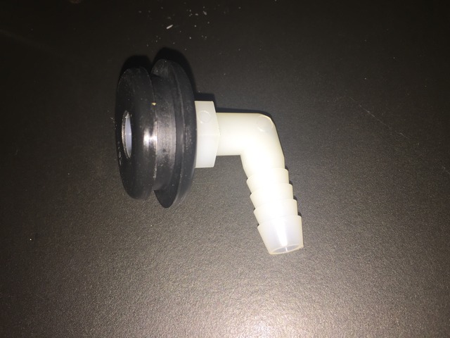
What part do I need to go into the grommet on the drivers valve cover?
MightyMouse has me a little intimidated on this project as I'm not really familiar with the LS engine PCV stuff.
Last edited by Mr. Black; Feb 2, 2019 at 09:49 PM.
Reason: Corrections from typing too fast.
The best solution given the parts needed vs supplied would be to get rid of the inline PCV valve and mount a fixed orifice PCV in the driver grommet. I have them for $5. this will be better for oil control in general and make life a little easier on your current catch can.
Thank you Mighty Mouse. I actually found a thread searching in the middle of the night (while I should have been sleeping) discussing this very topic. And yes it makes total sense and is even more simplified which I like. I'm hoping I can procure a simple AC Delco CV744C this morning at the local parts house so I can get a bunch more of this car put back together. Thanks again for your knowledge on this subject.
MightyMouse has me a little intimidated on this project as I'm not really familiar with the LS engine PCV stuff.
The Mighty Mouse catch can is actually pretty simple for an NA LS-motors. You get all the parts you need in one box. I figured it out in about 5 minutes. It probably took me 30 minutes total to remove the old system and install the new MM system.
If you are trying to piece together an existing PCV system with a catch can, then you might have troubles.
This. I tried making my own but it looked like ****. The MM system has the PCV valve integrated into the can. I used AN aluminum weld on bungs where it attaches onto the valve covers. I see too many self made systems that either:
1. Smell like **** for a street due to venting off in the engine bay
2. Result in blown rear main seals due to improper pressure release
Gas Monkey Built a 6-Wheel Ferrari Testarossa With a Corvette LT4 Engine
Slideshow: The controversial Ferrari F6 swaps its original flat-12 for a Corvette Z06-derived LT4 V8 and sends power to four rear wheels through a custom-built drivetrain.
7 Most Reliable High-Performance Engines GM Has Ever Built
Slideshow:These GM engines didn't just make huge power, they survived abuse, boost, track days, and six-digit mileage with a reputation for refusing to quit.
6 Common C5 Corvette Failures and What's Involved In Repairing Them
Slideshow: From wobbling harmonic balancers to failed EBCMs, these are the issues that define long-term C5 ownership and what repairs typically involve.
Retro Modern Bandit Pontiac Trans AM Comes With Burt Reynolds' Autograph
Slideshow: A modern Camaro transformed into a retro icon, this limited-run "Bandit" build blends nostalgia with brute force in a way few revivals manage.
Top 10 Greatest Cadillac V Series Performance Models Ever, Ranked
Slideshow: Cadillac didn't just crash the high-performance luxury vehicle party, it showed up loud, supercharged, and occasionally a little unhinged...
Coachbuilt N2A Anteros Is an LS2-Powered C6 Corvette In Italian Clothes
Slideshow: A one-off sports car that looks like a vintage Italian exotic-but hides a C6 Corvette underneath-just sold for the price of a new mid-engine Corvette.