When you click on links to various merchants on this site and make a purchase, this can result in this site earning a commission. Affiliate programs and affiliations include, but are not limited to, the eBay Partner Network.
DIY - Junkman's Engine Oil Pressure Sensor Replacement/Relocation for Dummies!
(This write up was written for the C5 Corvette (1997-2004). However, those of you with LS1 engines may find it just as useful. This DIY was written with the total novice in mind, which is what I need when working on my car. )
Well folks, it's been 2 years in the making (or actually in the procrastinating)!
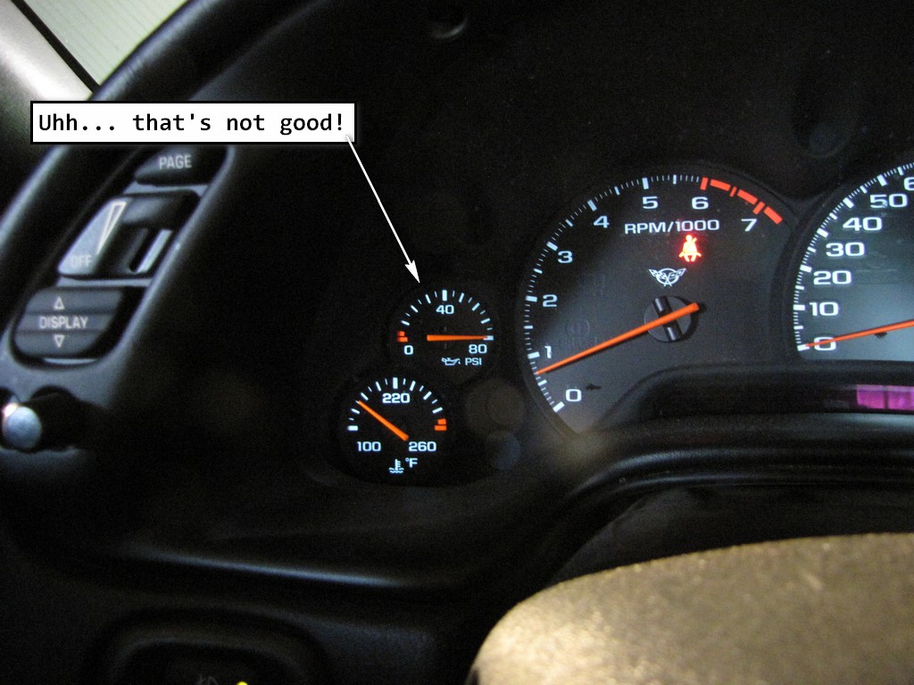
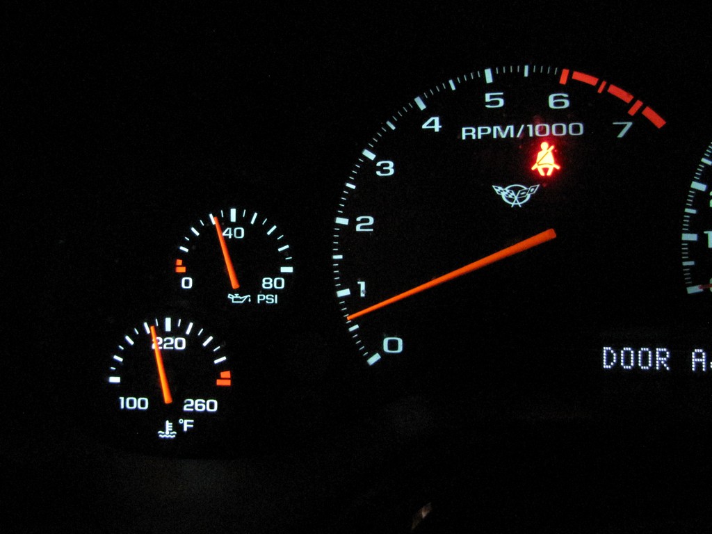
So, when you get in the car and start it up, is this what you see?
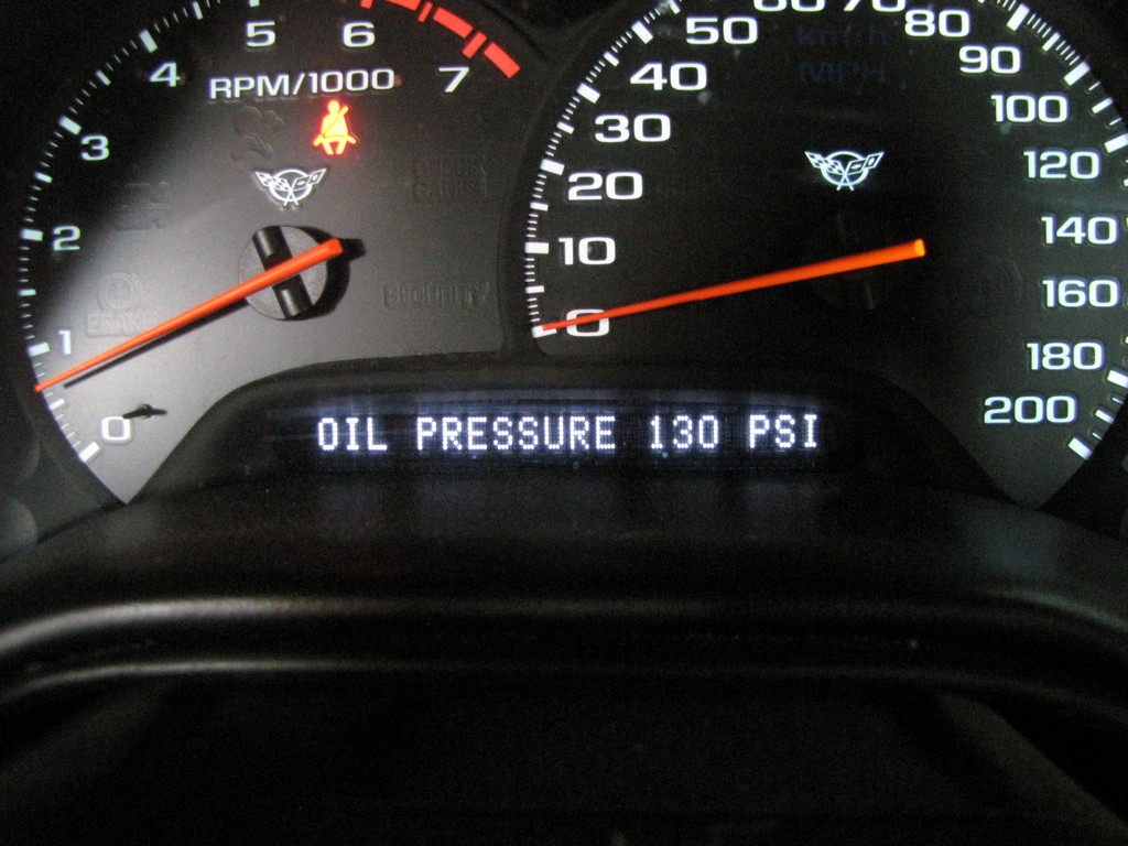
When you check you digital information center (DIC), you also see this:
Actually, these reading are impossible because a engine cannot make more oil pressure than the engine is designed to make. It can loose oil pressure, but it cannot create more.
To verify that your sensor has gone south, do this. Turn the key to the on position but do NOT start the car. Your oil pressure gauge will sweep and settle back to zero. If it does not settle back to zero, then you know your sensor or gauge is bad because a engine that is not running cannot produce oil pressure.
On the flip side, if your gauge stays at zero after you start the car and your engine doesn't sound like a 800 pound gorilla is knocking on the hood, then your sensor or gauge is probably bad. If your engine has no oil pressure, believe me, you will quickly realize it! The gauges very, very seldom go out in these cars. The sensors, however, are notorious for failing. Once you replace them, they have been known to go out again rather quickly. This could be from guys over-torquing the sensors during the install (gorilla torque is not needed once during this repair). I don't know as I have not repaired a hundred of them but the reason I relocated mine is because I don't want to have to deal with this repair again. Now my EOP sensor repair is a 10 minute job, not 2 days.
I have been putting this off for so freakin' long that it ain't funny. But since my dead oil pressure sensor (OPS) starting leaking, it was time to get this DIY out of the way. It had started to drip on my exhaust and stink like burning oil (duh). That was the point of no return for me, it had to go! Plus, I have been promising to do this write-up for the longest so this is for all the guys and gals who have been patiently waiting.
Tools Needed
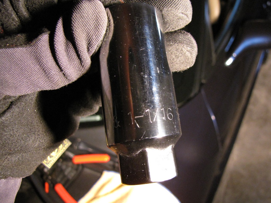
The tools you'll need are not all that uncommon, however, there are a few "must have" tools that will make the job MUCH easier. The engine oil pressure sensor socket is a 1-1/16 deep socket:
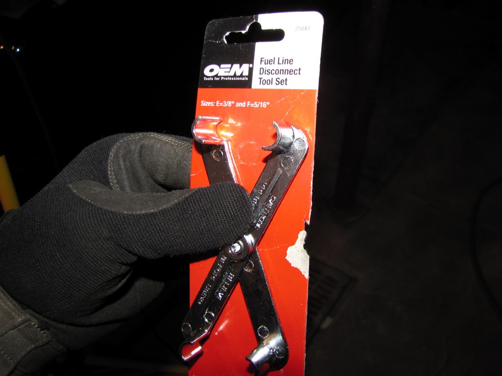
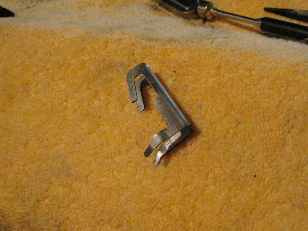
Also, the tool needed to separate the fuel line from the female quick connect fitting:
Note the E & F sizes on the packaging.
A small pick or small flat-blade screw driver comes in handy during this repair so add one of those to the list.
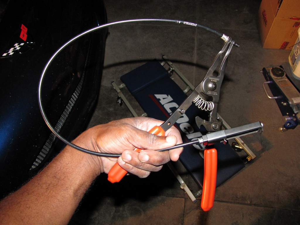
Lastly, hose clamp pliers are another thing that will make this job a lot easier too. If you don't have a pair, get some. You'll thank me later.
I'm going to write this as close to the eSi GM Service Manual as possible. That is what I used and it is usually 99% dead on. You may or may not find a short cut here or there but after doing the job as the manual states, I can see why the instructions are written the way they are. The instructions called for the manifold and the fuel rails to be removed as 1 unit. If you are not replacing the manifold, this makes perfectly good sense as you don't want to go and break the fuel injection connections if it is not necessary.
At first glance, this is a very daunting looking repair. In reality, it is not that bad at all. The service manual calls for less than 2 hours for the whole job but keep in mind that those numbers are in a shop with every tool and a lift for the car. That's also for someone who knows what they are doing, which is NOT me. I think I could do it in 4 hours now, but then I'm very slow and methodical with my repairs and upgrades. That's why they work the first time.
So as you sit here wondering if you should even try this, note that I am NOT a mechanic by any stretch of the imagination, I can't identify half the crap I took apart, it took me 2 days to do this and I was scared to death to turn the key once I was done.
So there, you have company. :laughing:
Now for the repair!
Replacing or Relocating the OPS
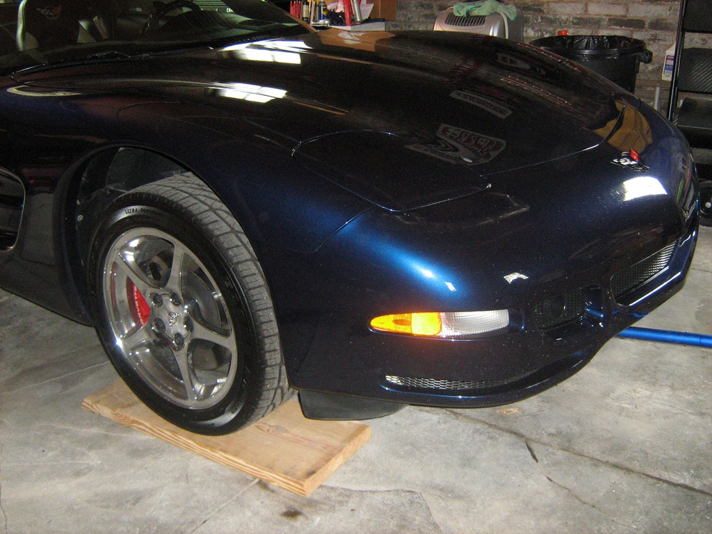
1. Drain the cooling system. In order to do this, you will need to raise the car. for those who don't have a lift, here's the way I do it.
Drive the front of the car up on some 2X12's.
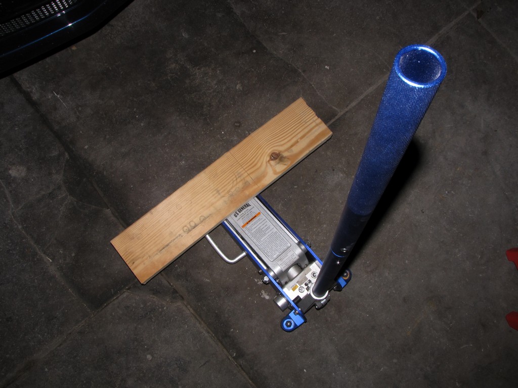
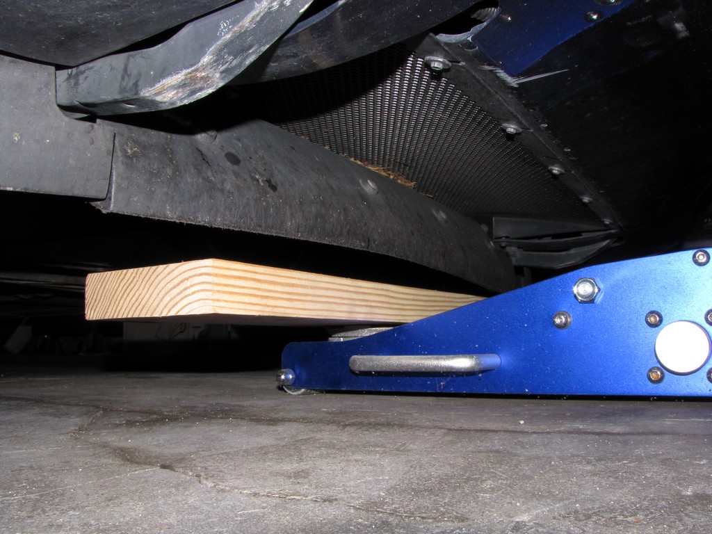
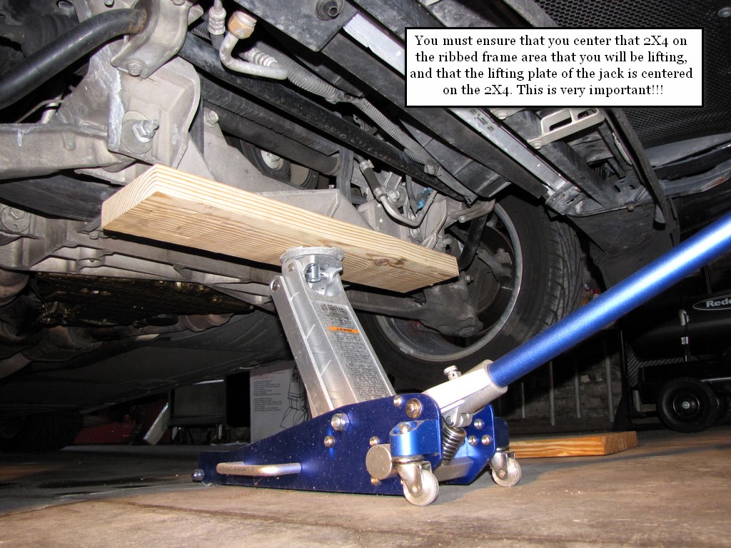
Using a low profile jack that I got from Harbor Freight, I center a 2X4 on the jack plate and run it under the front of the car.
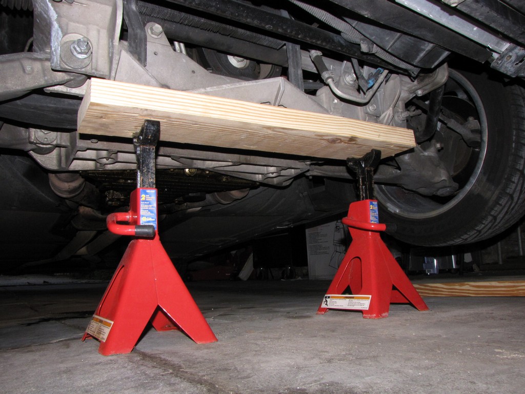
Once in place and lifted, I support the car with jack stands.
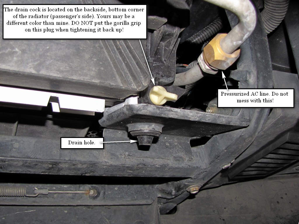
There is no need to raise the rear of the car. You just need to get the car high enough for you to roll under there and loosen the drain ****.
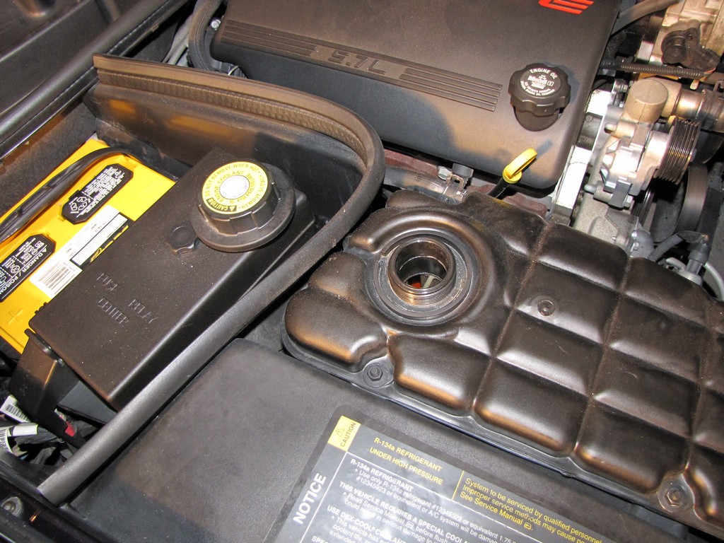
Remove the overflow tank cap and get your safety glasses on. Remember, safety first!
:thumbsup:
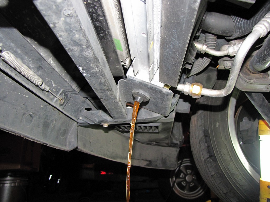
The actual draining of the system is pretty easy. You simply loosen the drain **** (hey, I didn't name it... that's what it's called) and you will see the fluid begin to flow. You will turn it counter-clockwise. Do not completely remove the drain ****, just loosen it until the antifreeze starts flowing real good. Now go have Dagwood Pizza and your favorite drink because it will take the fluid a little bit to completely drain..
Once all of the coolant has drained, close the drain **** and lower the car. You can reuse your old coolant if you want to but if it wasn't changed recently, I don't know why you would. Don't be a cheap azz, buy some new fluid for your baby. Don't get the 50/50 stuff because you're paying for water, which is free (however, if you don't have access to distilled water, buy the 50/50 stuff). Other than that, buy the full strength stuff and dilute it with distilled water. You can use A 50/50 mixture of clean, drinkable water but use only GM Goodwrench� DEX-COOL� or Havoline� DEX-COOL� silicate-free coolant. It takes approximately 11.9 liters (12.6 quarts) to refill the cooling system.
After the system has drained, close the drain **** (don't break it with the pliers by putting the gorilla torque on it), and lower the vehicle.
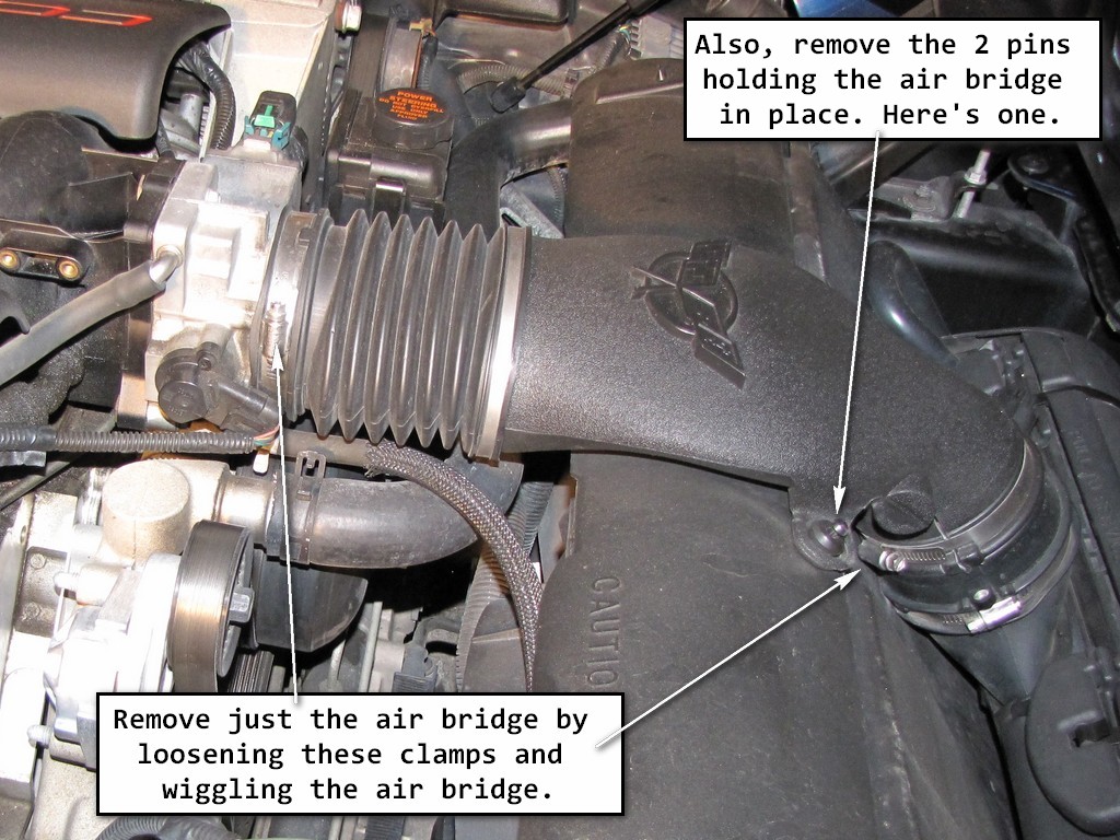
At this point, you need to remove the air bridge. Every since I learned how to remove my air bridge/filter as a unit, I've always done it that way. After you do it once, it's real easy to do it that way. Instead of posting the pictures here making this DIY even longer, here's another write-up that I did that shows how to remove the air bridge and filter as a unit. Do this before proceeding, or just remove the air bridge by itself.
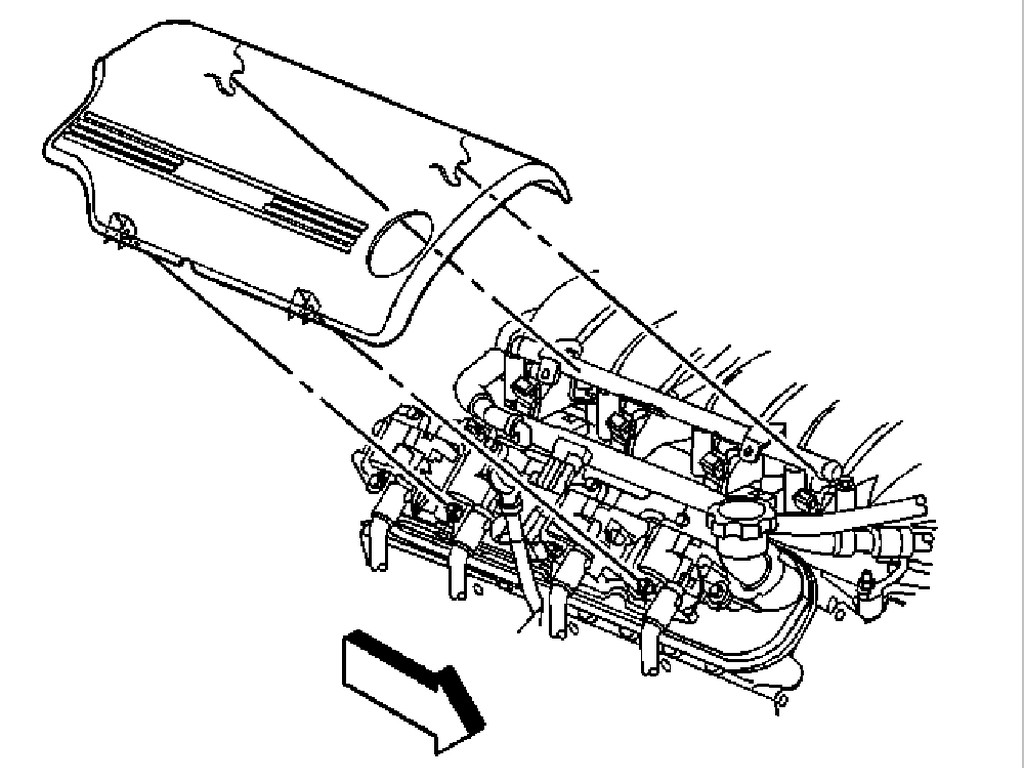
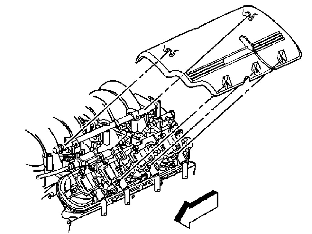
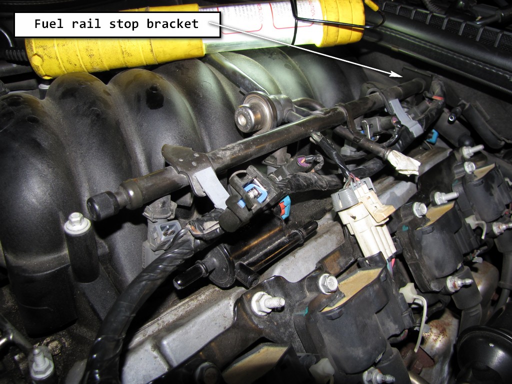
2. Remove the fuel rail covers. For those who may have never done so, they simply pop off. Just give them a good, careful tug. Each side is slightly different. Here's a shot from the manual. For orientation purposes, the arrow depicts the front of the car.
In this write up, you will notice that I also removed and cleaned my throttle body. Most guys are not going to go through all that trouble to clean their throttle body but you all know me (most guys just leave it attached to the manifold). Thorough is my middle name. If I'm tearing something up, then I'm going for broke! Thus, as you read these instructions, I'll supply pictures from the manual if necessary as my throttle body was removed first before I started this repair.
At this point, you want to clean the area around the manifold where it meets with the aluminum heads. The reason being is a lot of you will have all kinds of gunk and dirt under your fuel rail covers that has probably never been cleaned. You do not want this dirt and crap falling into the engine block! You can used compressed air if you have access to that, however, I used brake parts cleaner followed immediately with a low flow of water from the garden hose. Brake clean will loosen up and remove ANY kind of dirt but it is a expensive way to get your motor clean. You won't have to scrub anything though!
Last edited by Junkman2008; Aug 28, 2012 at 07:53 AM.
3. Remove the fuel feed hose by doing the following:
Disconnect the negative battery cable.
Relieve the fuel system pressure by loosening your gas cap.
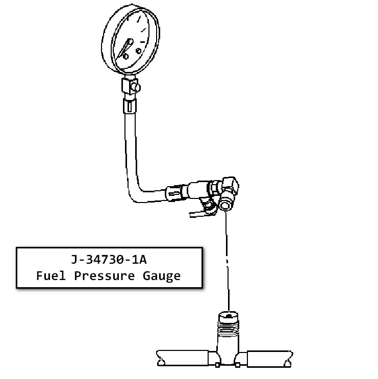
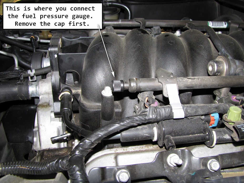
Now the manual calls for you to connect the J-34730-1A fuel pressure gauge to the fuel pressure connection. It states to wrap a shop towel around the fitting while connecting the gauge in order to avoid spillage.
I didn't have that tool and that puppy cost $213.58. Needless to say, I didn't rush out and buy it. What you basically do is connect this tool, attach a drain hose to it and bleed the excess fuel off into an approved container by turning a lever on the tool. Since I didn't have this tool, I got a bunch of paper towels ready for when I disconnected the fuel line. I had some fuel spillage when I did so and fuel remained in the fuel rails when I removed the manifold (I found that out when I pulled the manifold up off the car).
Thus, be cognizant if you have no way of relieving the fuel pressure when disconnecting the fuel line and have plenty shop towels ready!
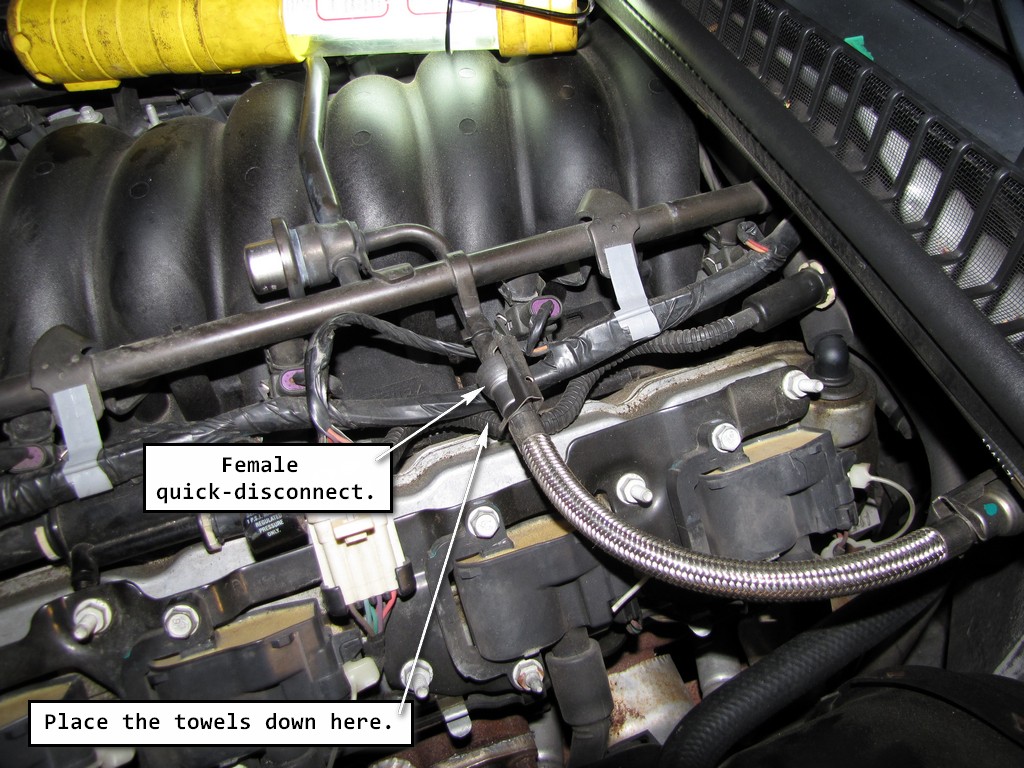
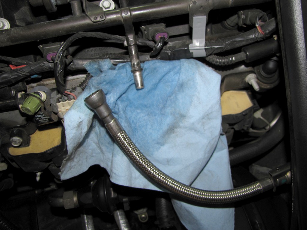
Next, get plenty of shop towels and place them under the fuel line where it connects to the at the female connector of the fuel feed hose. You will have some fuel spillage here.
Remove the fuel line coupler.
Fuel line coupler.
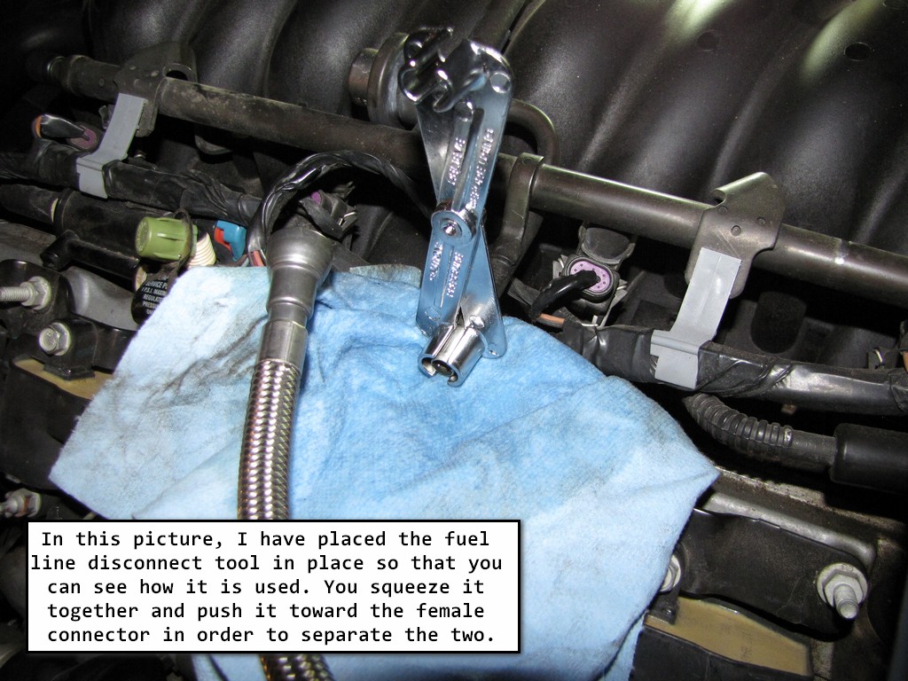
Then using your fuel line disconnect tool, separate the female connector from the fuel line by inserting the tool into the female connector, then push inward in order to release the locking tabs. The fuel line will then separate from the female connector of the fuel feed hose.
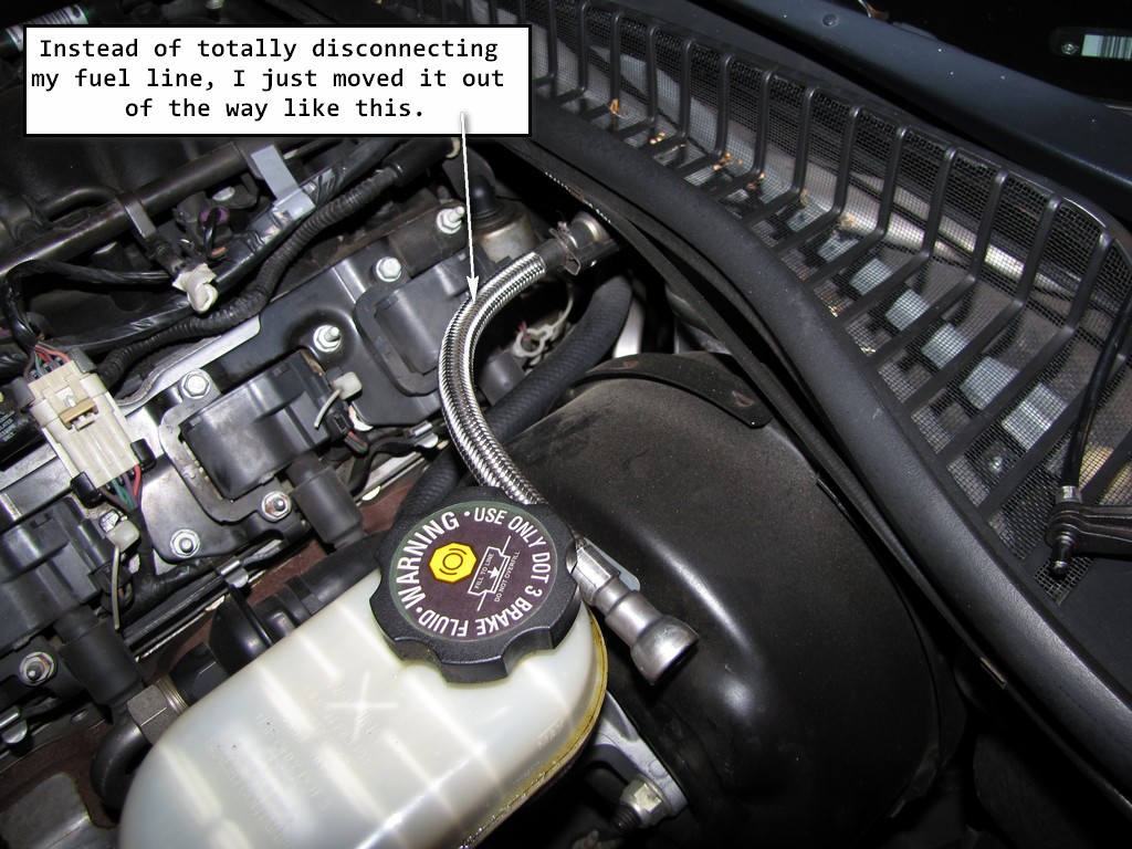
Clean both connectors. The manual calls for you to remove the fuel feed hose by disconnecting it at the other end. I didn't find this necessary and left mine connected to the car. The reason was probably so that you didn't damage that fuel line so either remove it or be very careful around it.
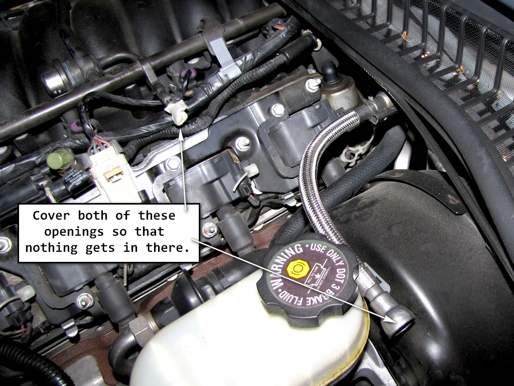
4. Cap the chassis fuel pipe and the fuel rail pipe in order to prevent possible fuel system contamination.
5. Check the fuel feed hose for any damage and replace if necessary.
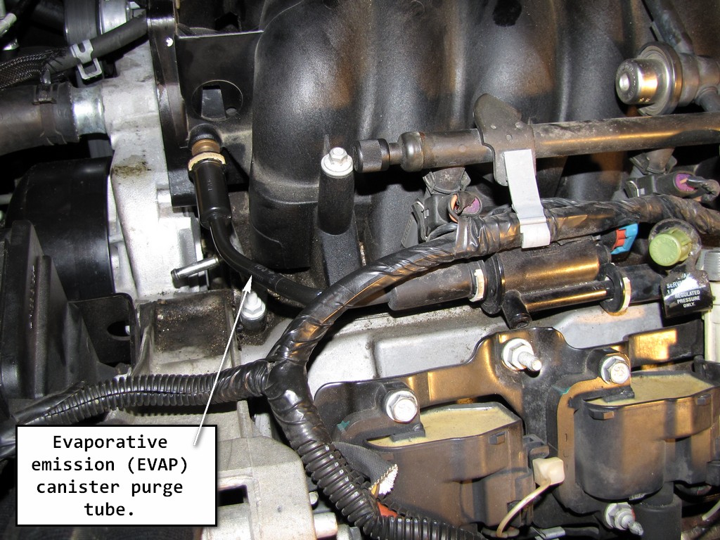
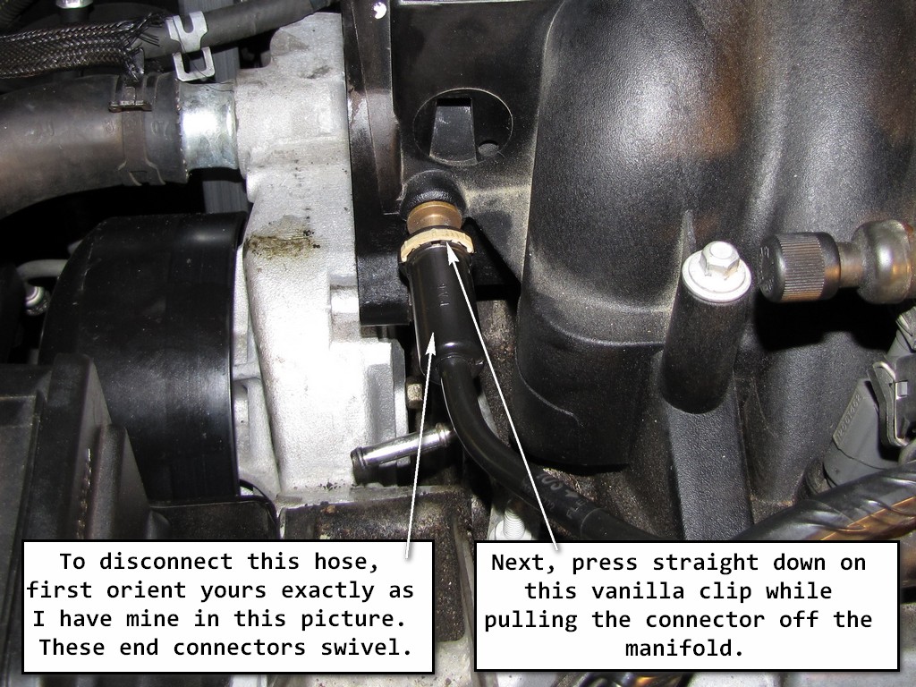
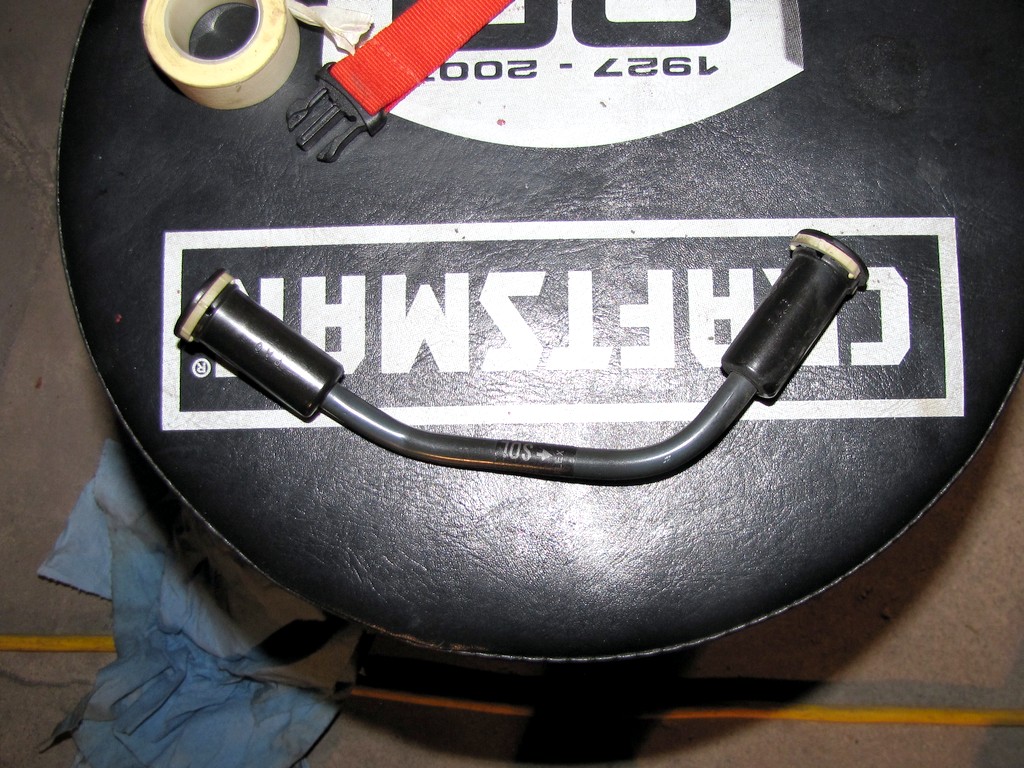
6. Disconnect the evaporative emission (EVAP) canister purge tube from the intake manifold.
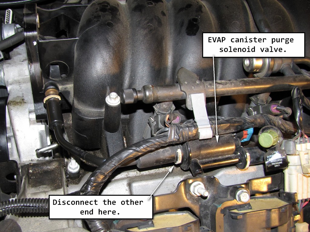
7. Disconnect the EVAP canister purge tube from the EVAP canister purge solenoid valve.
8. Remove the EVAP canister purge tube.
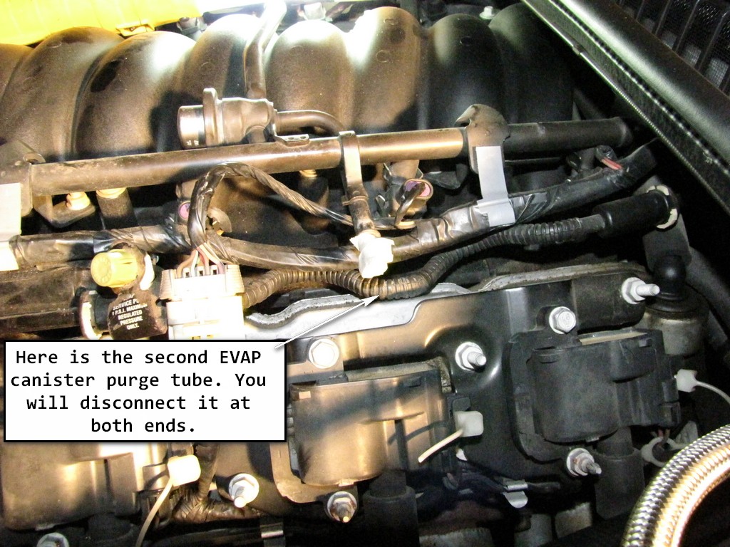
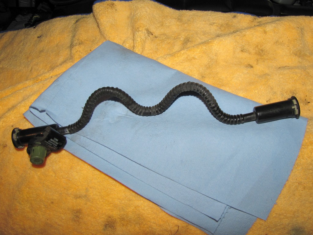
9. Disconnect the EVAP canister purge tube from the EVAP canister purge solenoid valve and the fuel feed line. That sounds exactly like what you just did, but there are 2 EVAP canister purge tubes. One tube is connected to one end of the EVAP canister purge solenoid valve, and another tube is connected to the other end. They do not look the same, although they do share the same end connectors. Disconnect at both ends and remove from the engine.
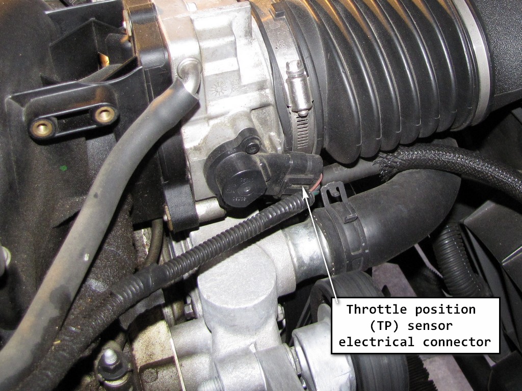
10. Disconnect the throttle position (TP) sensor electrical connector.
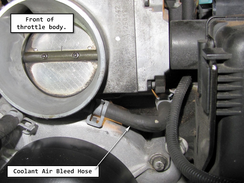
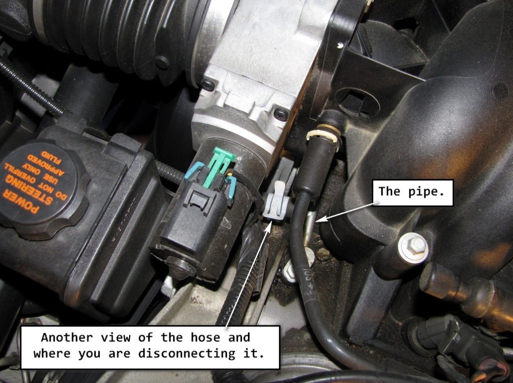
11. Remove the coolant air bleed hose from the pipe. At this point, if you don't own a pair of hose clamp pliers, you will wish you did. They make this step MUCH easier!
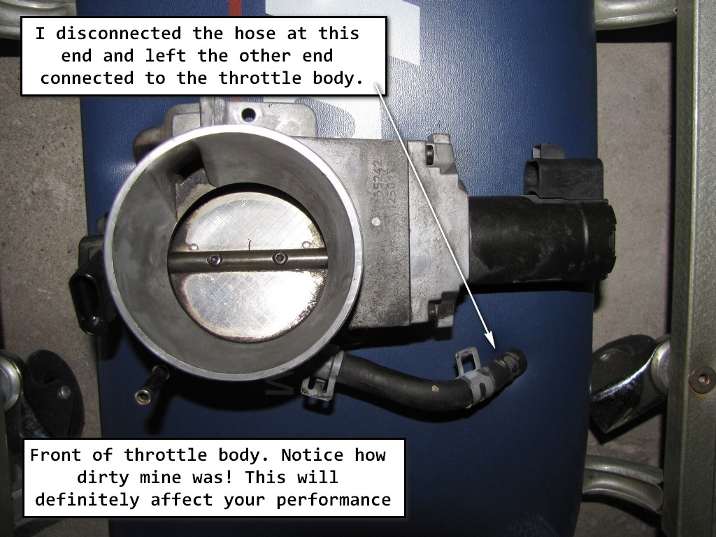
The manual calls for you to completely remove the hose. The hose is connected at one end to the pipe, and at the other end to the throttle body. What I did was disconnect it from the pipe only, and left it attached to the throttle body. When I removed the throttle body to clean it, I again left the hose attached to the throttle body.
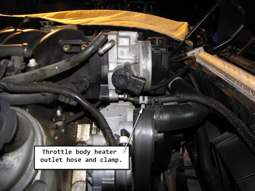
12. Reposition the throttle body heater outlet hose clamp at the throttle body, and then disconnect the hose. The manual again called for the hose to be completely removed but I just folded it back and out of the way.
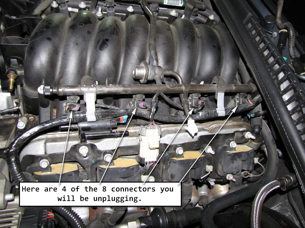
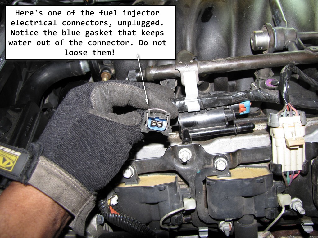
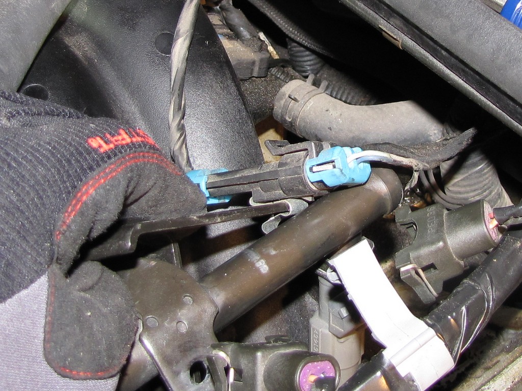
13. Disconnect all the fuel injector electrical connectors (8 total).
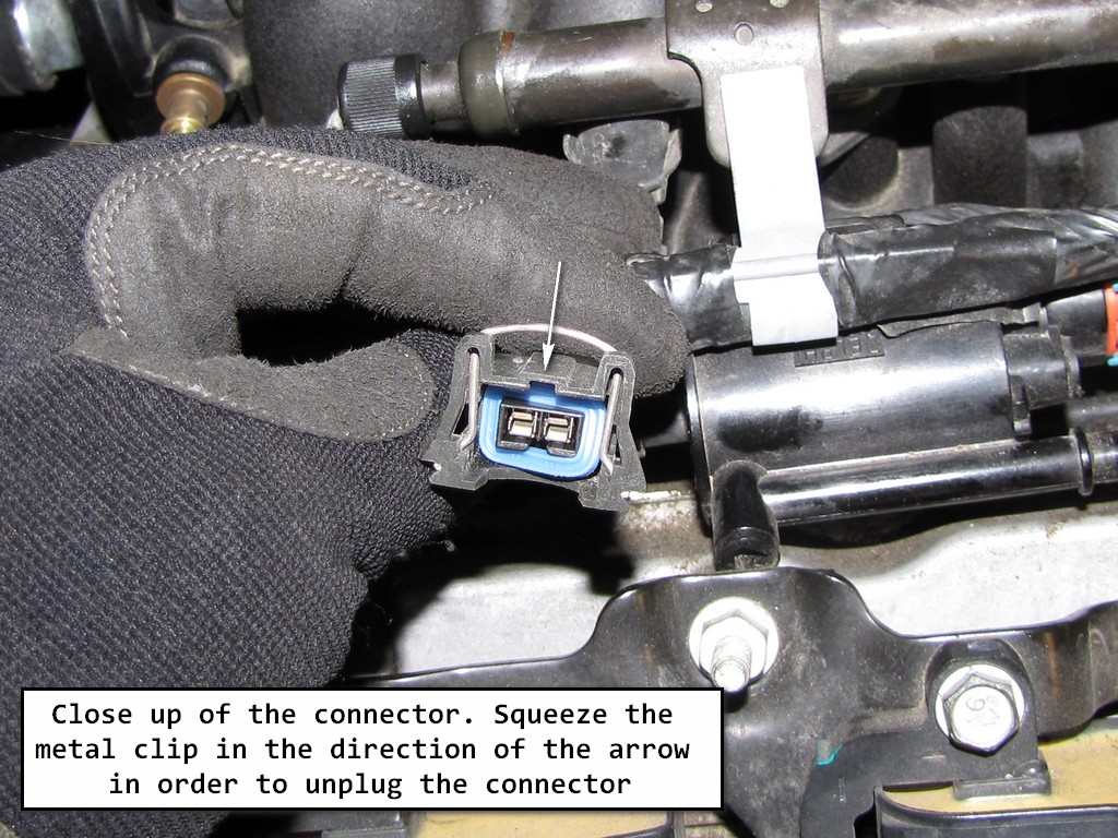
Now this is a little tricky but not all that hard at all. Each connector has a metal clip that holds them in place. What you will do is squeeze that metal clip which will free the connector and allow you to unplug it.
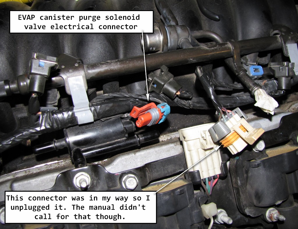
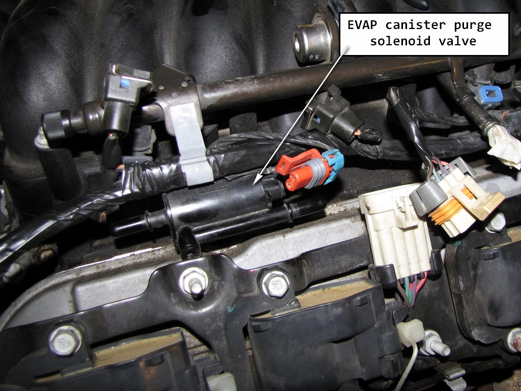
14. Disconnect the EVAP canister purge solenoid valve electrical connector.
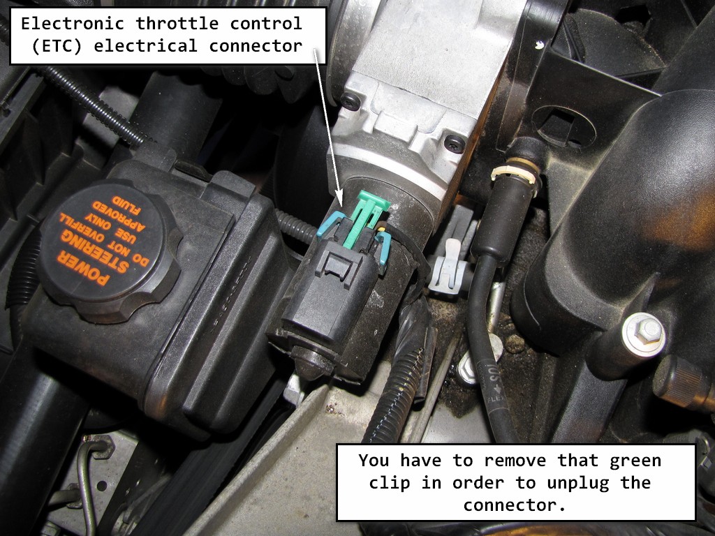
15. Disconnect the electronic throttle control (ETC) electrical connector.
(FYI - This connector is plugged into the throttle body. By this time during my repair, I had already removed my throttle body to clean it)
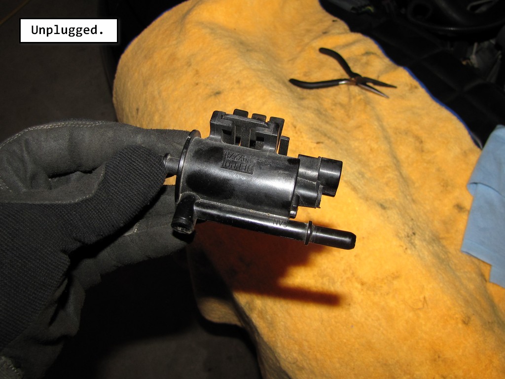
16. Remove the EVAP canister purge solenoid valve from the bracket.
I found it much easier to remove the EVAP canister purge solenoid valve and the bracket as one piece.
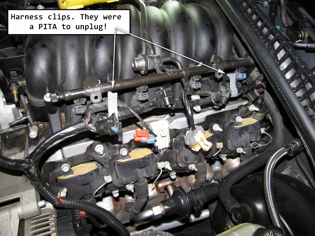
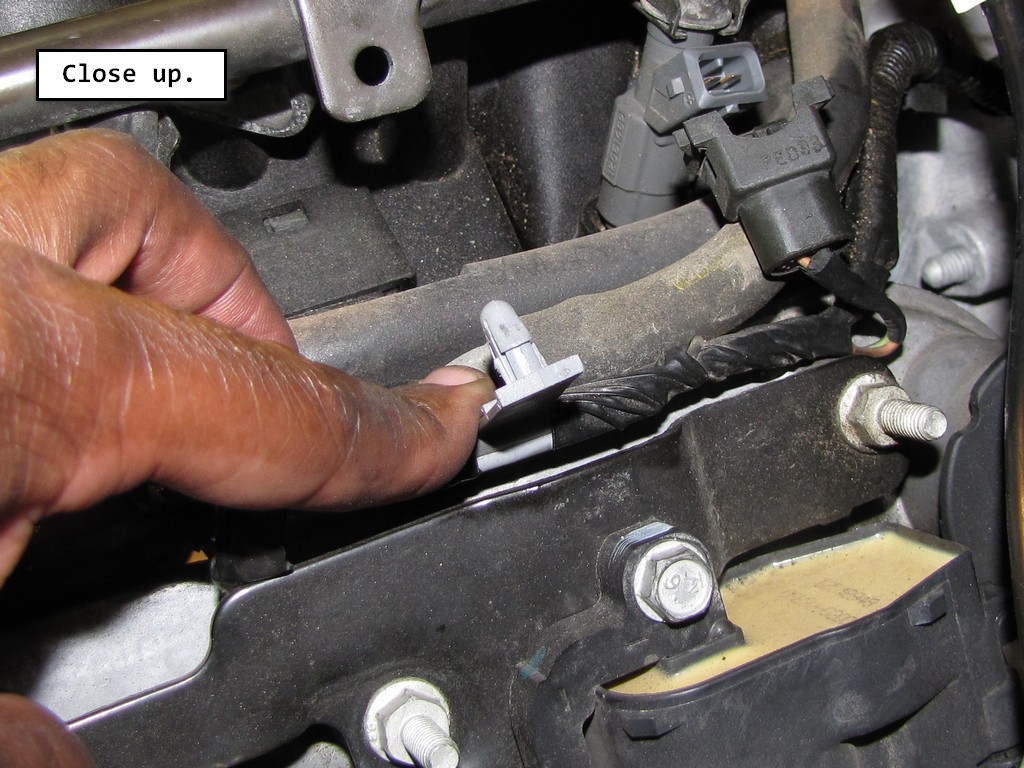
17. Disconnect the harness clips at the fuel rails. There are 2 on each side of the manifold. Once disconnected, move the branches of the wiring harness out of your way.
18. Disconnect the power brake booster vacuum hose at the booster.
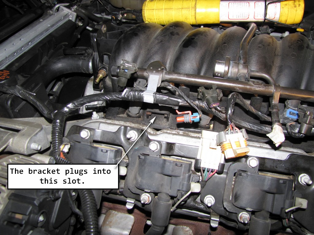
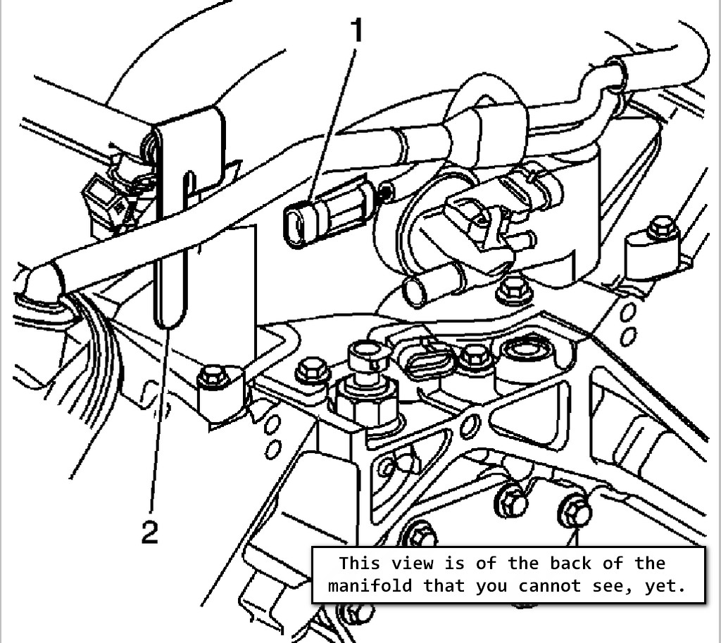
19. Remove the knock sensor wire harness (1) clip from the fuel rail stop bracket (2).
FYI - I didn't do it this way because it was a PITA to do. What I did end up doing was detaching the fuel rail stop bracket from the manifold and once I was able to move the manifold forward, detach it at that point. Here is another picture that shows how the harness is clipped to the bracket.
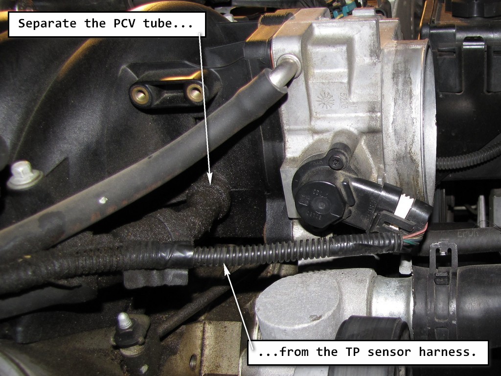
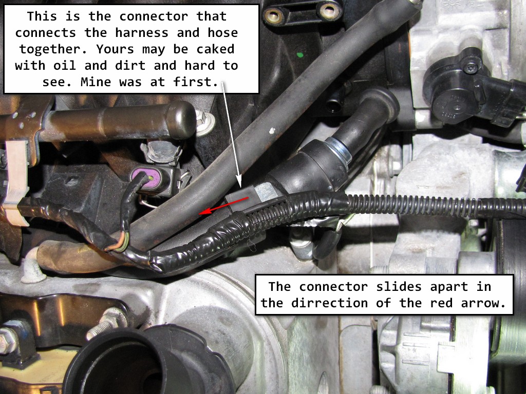
20. Remove the throttle position (TP) sensor harness clip from the positive crankcase ventilation (PCV) tube.
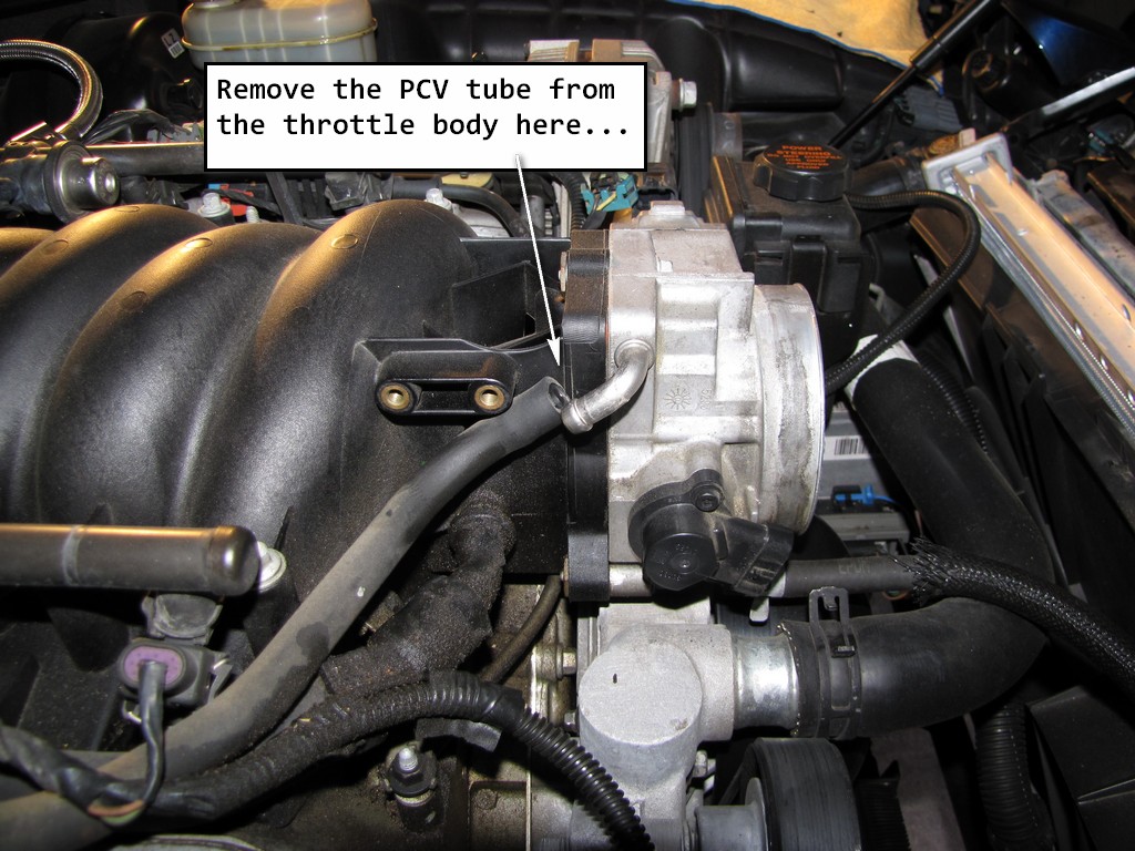
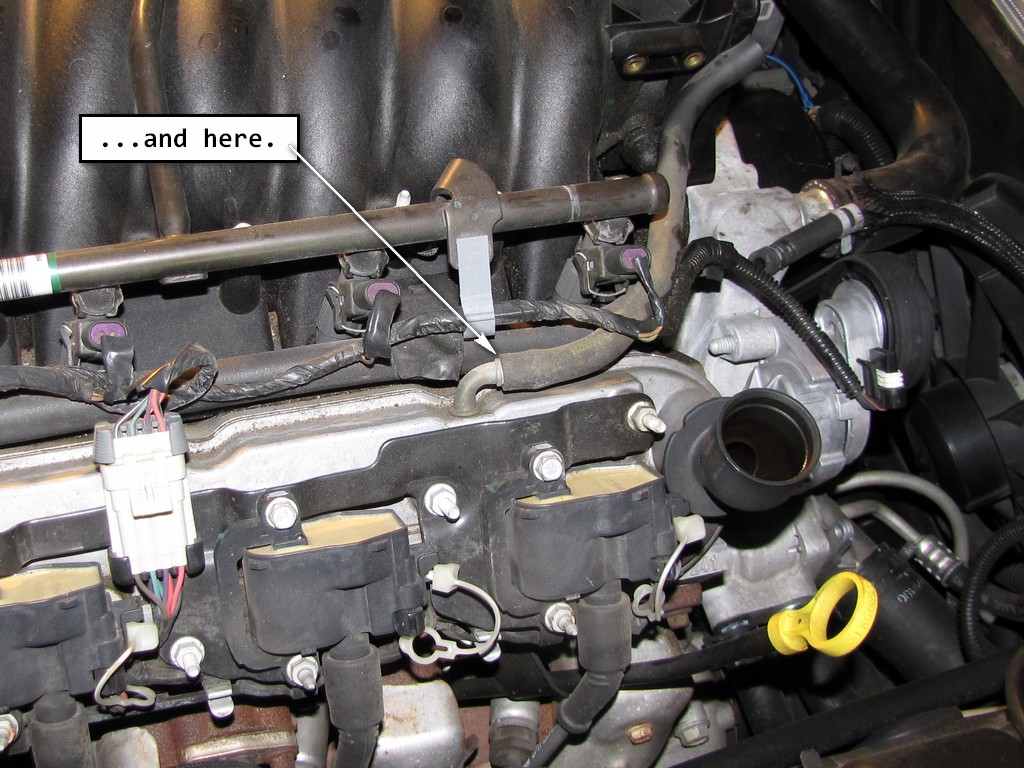
21. Remove the PCV tube from the right rocker arm cover and throttle body.
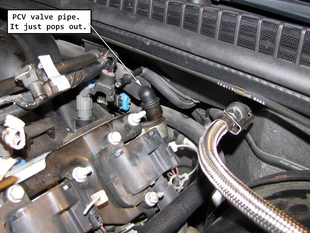
22. If equipped with the regular production option (RPO) LS1 engine, remove the PCV valve pipe from the left rocker arm cover.
Last edited by Junkman2008; Apr 17, 2024 at 12:20 AM.
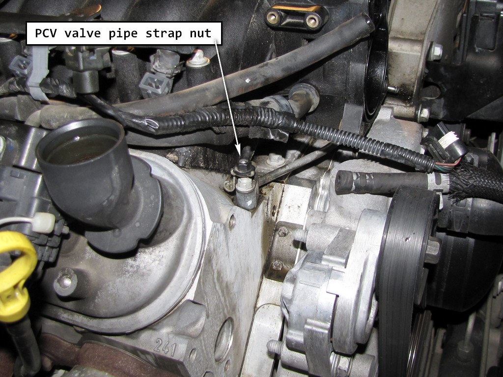
23. If equipped with the RPO LS1 engine, remove the PCV valve pipe strap nut.
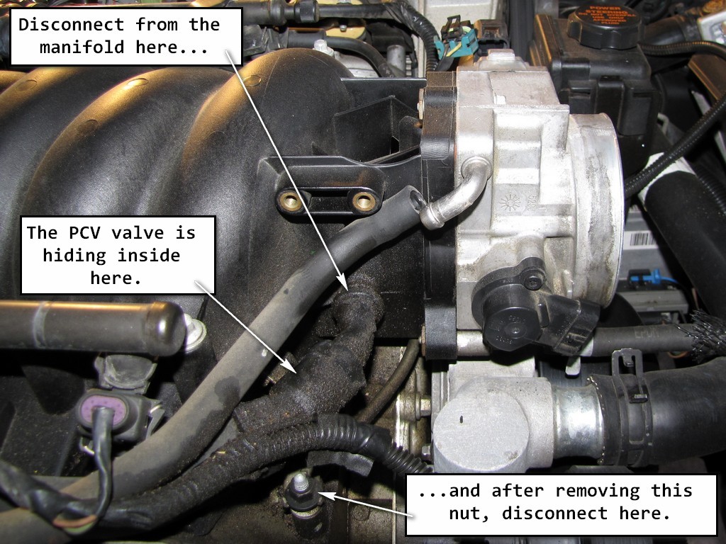
24. Remove the PCV valve pipe from the right rocker arm cover and intake manifold.
FYI - Now is a good time to replace that PCV valve, which is somewhat hidden. As you can see by the mess of oil in that area on my car, I needed to replace mine a long time ago!
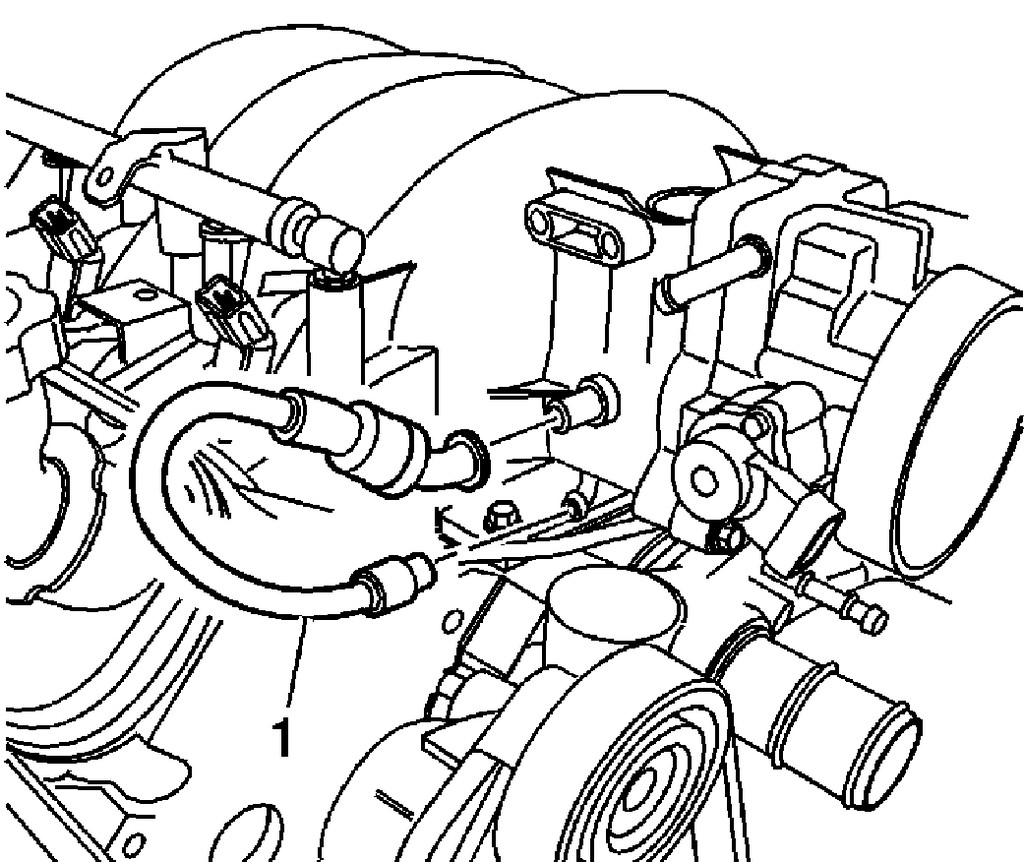
25. If equipped with the RPO LS6 engine, remove the PCV valve hose (1) from the valley cover and intake manifold.
FYI - I have an LS1 so this step was not required for me.
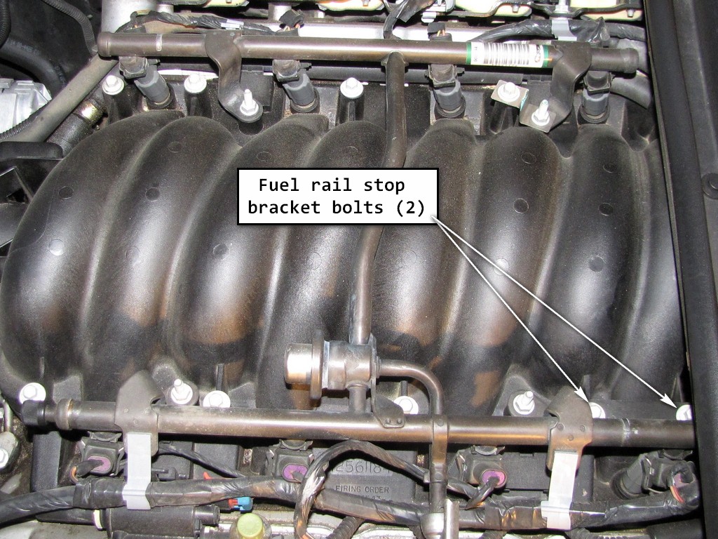
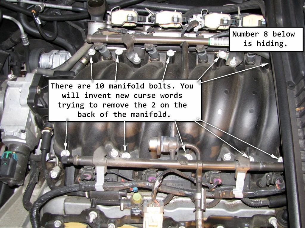
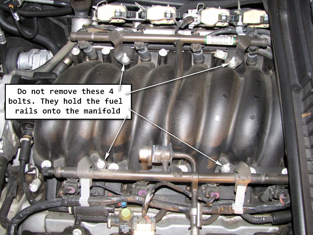
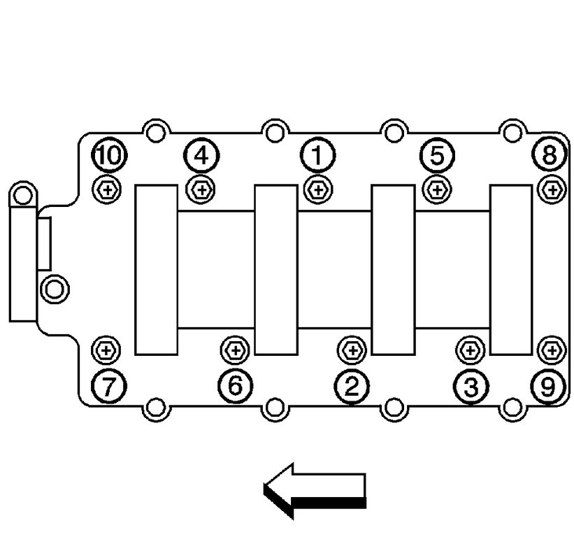
26. Remove the intake manifold bolts and fuel rail stop bracket.
Important Notice! - The number 8 manifold bolt is not shown in the pictures below (passenger's side, furthest back on the manifold). Numbers 8 & 9 are the two bolts in the very back of the manifold, which are a PITA to remove. You will need to remove all the other manifold bolts first, and then loosen bolts 8 & 9 until they can be freely moved up and down. At that point, you will need to hold them up and out of their holes, while at the same time moving the manifold forward
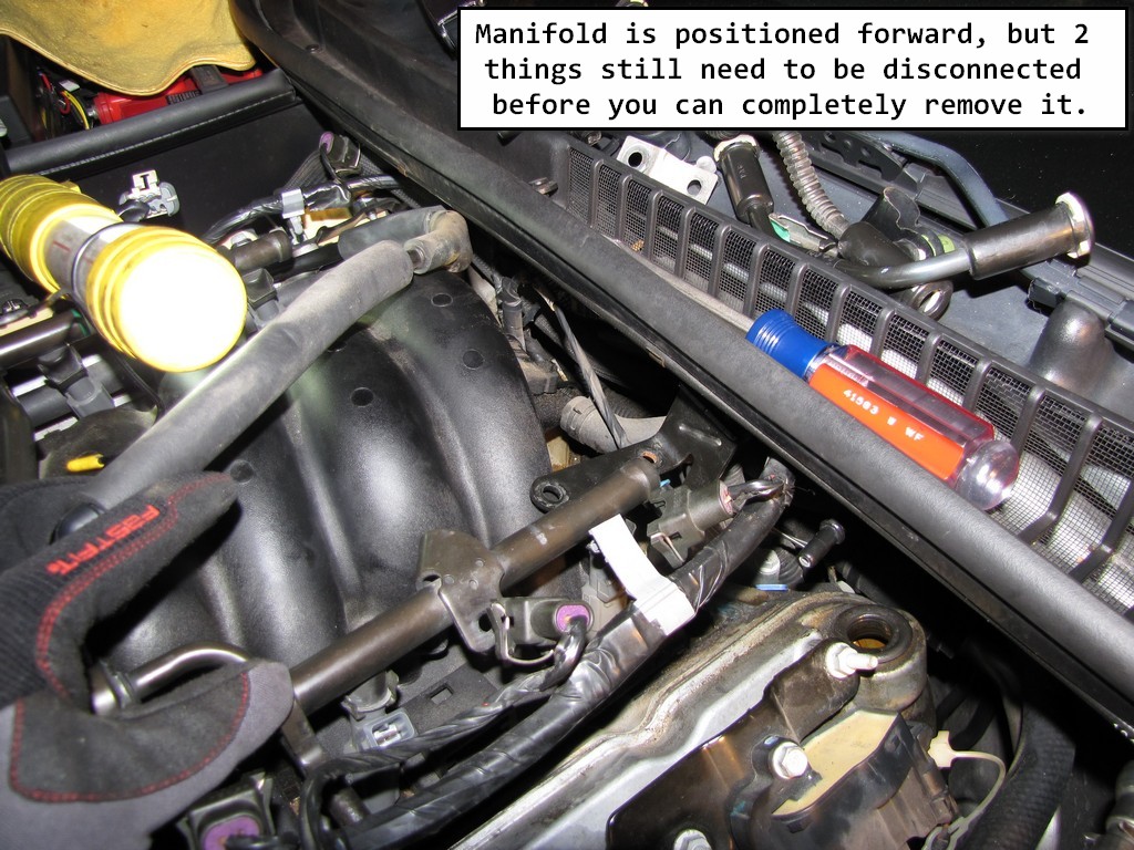
27. Position the intake manifold forward.
Have fun! :thud:
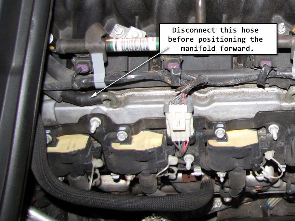
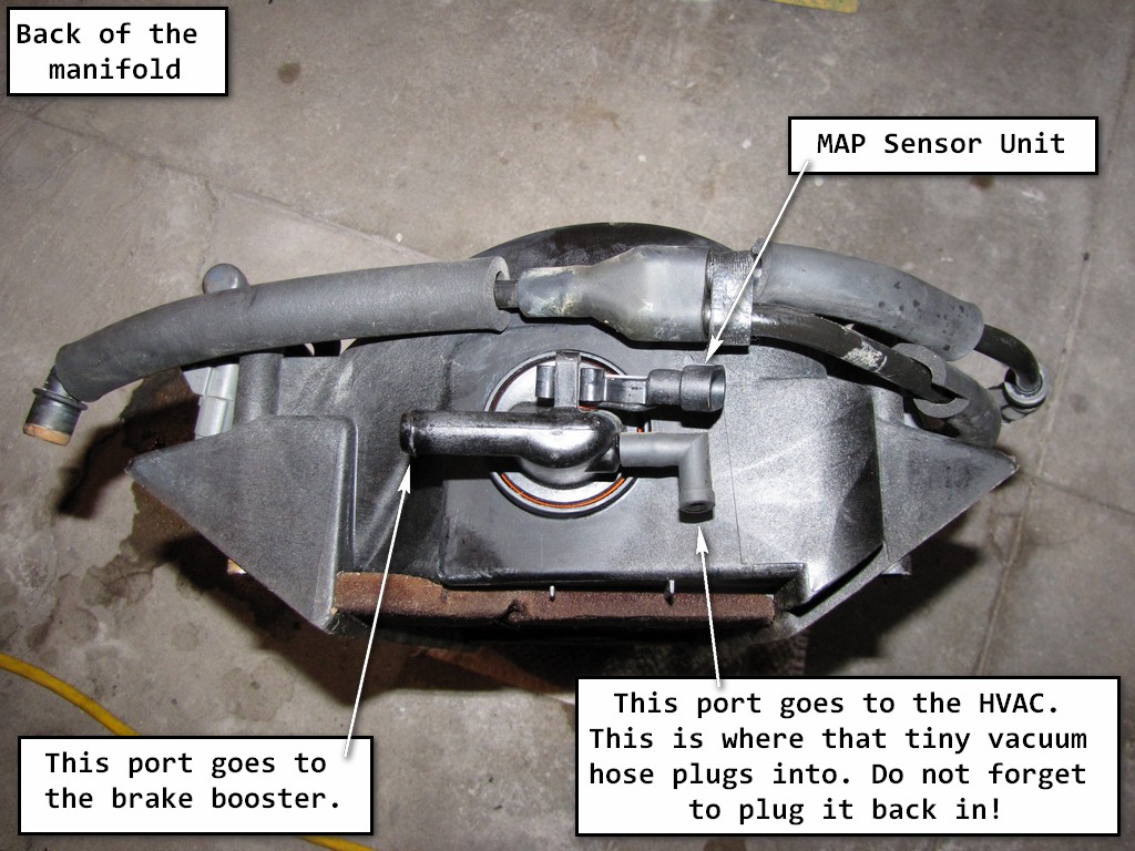
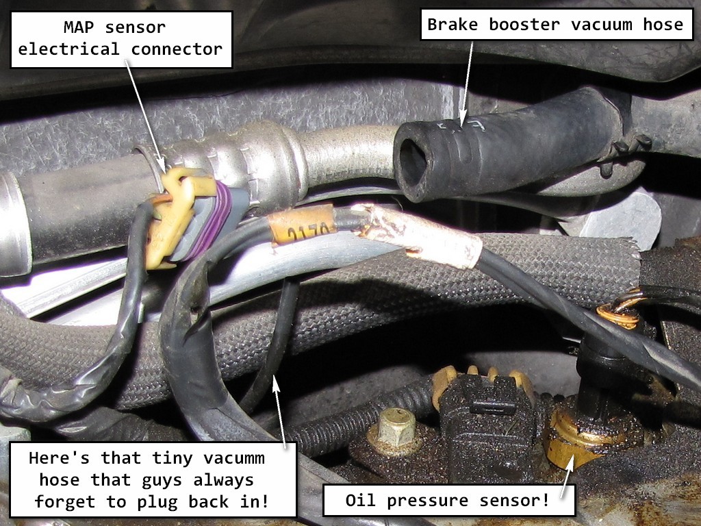
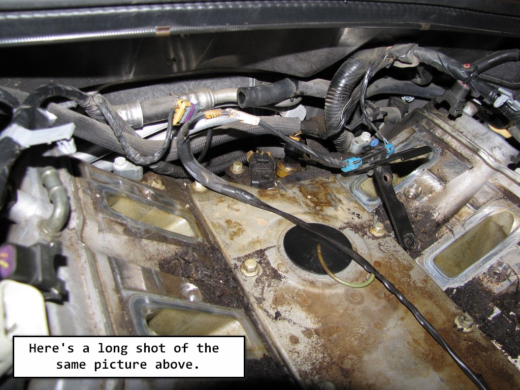
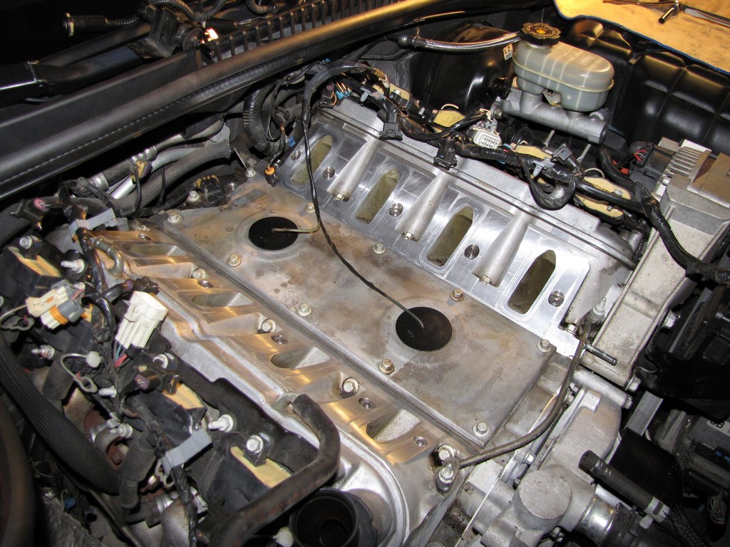
28. Disconnect the manifold absolute pressure (MAP) sensor vacuum hose and the MAP electrical connector.
Now at this point of the repair, it would have been nice to be able to see what is behind the manifold so that I could unplug those items. I didn't have that luxury and since I know nothing about engines, this was an adventure. As a matter of fact, I went to bed and continued working on this again the following morning because I couldn't figure it out. However, YOU won't have that problem because I'm going to let you see what needs to be disconnected BEFORE you try. I'm going to save you folks who are doing this repair a boat load of headaches. Check out these pictures:
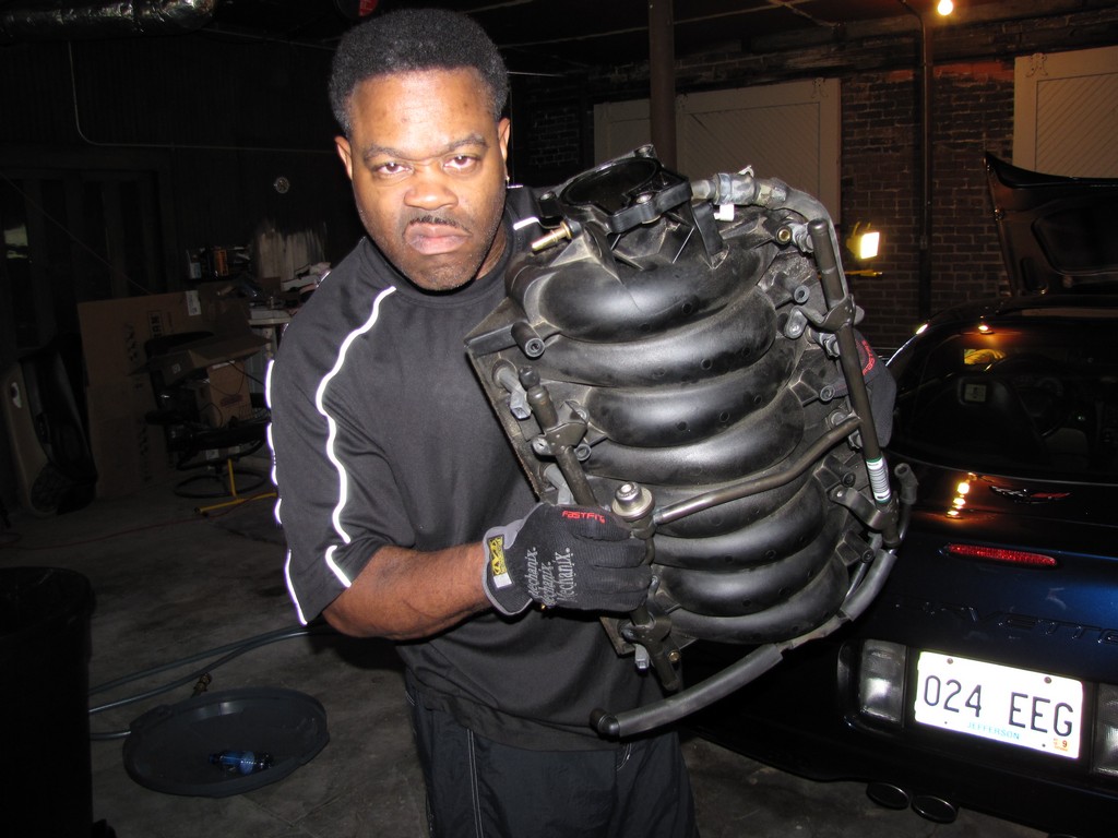
Once you complete step 28, you are ready to remove the manifold. At this point, you will probably look like me.
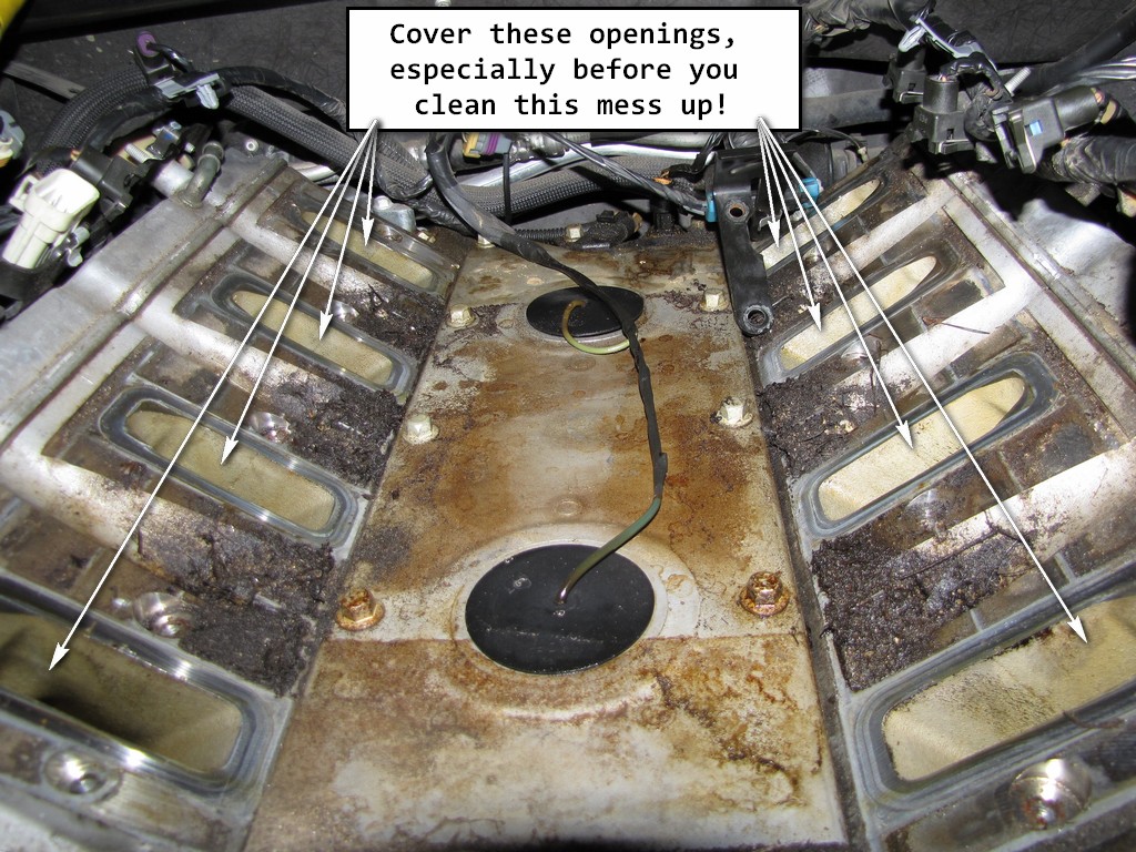
Important
Use some shop rags to close off the openings on the heads. You absolutely do not want any dirt, debris or tools falling into that area!
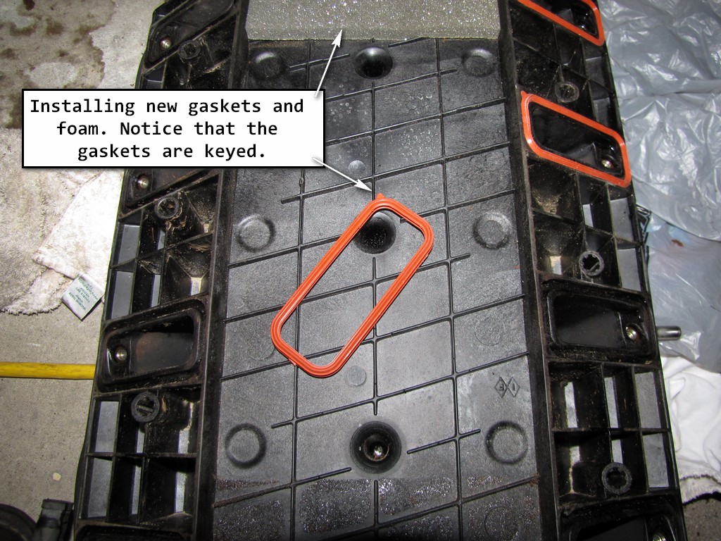
29. Remove the intake manifold gaskets and foam pieces. Discard them. Your new gasket set should have both new foam and gaskets.
30. Clean the manifold. It is best to give the manifold a solvent bath, however, if you don't have a tank to clean it in then get a bunch of cans of throttle body cleaner and spray the hell out of the inside and underside. Make sure you clean the grooves where the new gaskets are going.
31. Replace the gaskets and foam on the manifold.
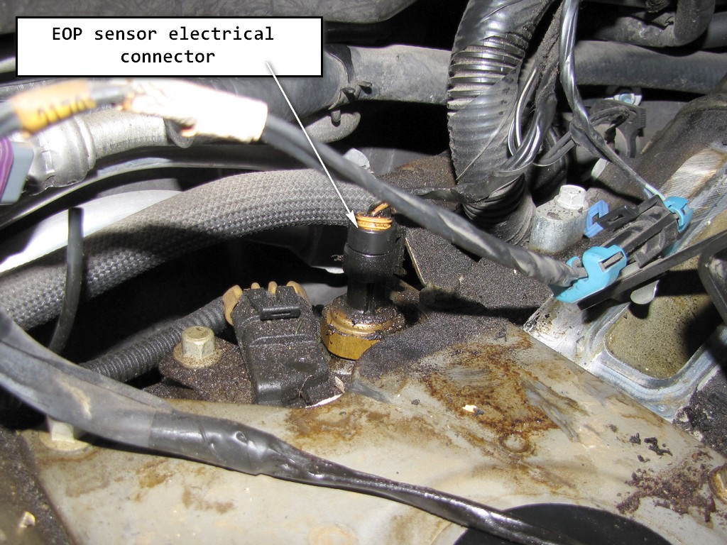
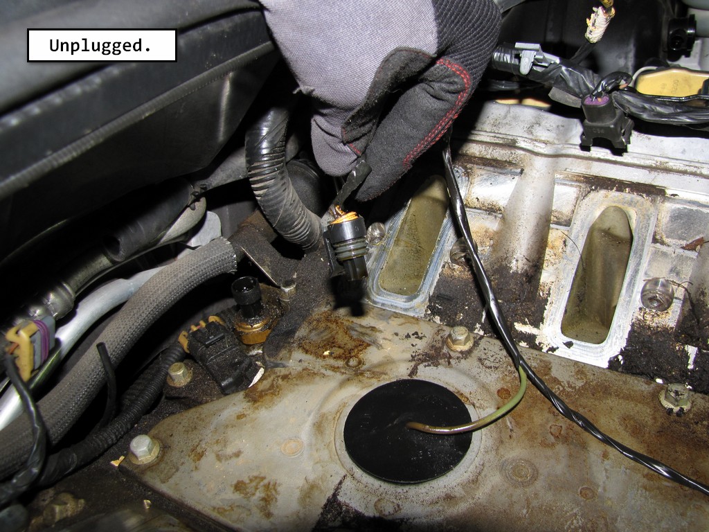
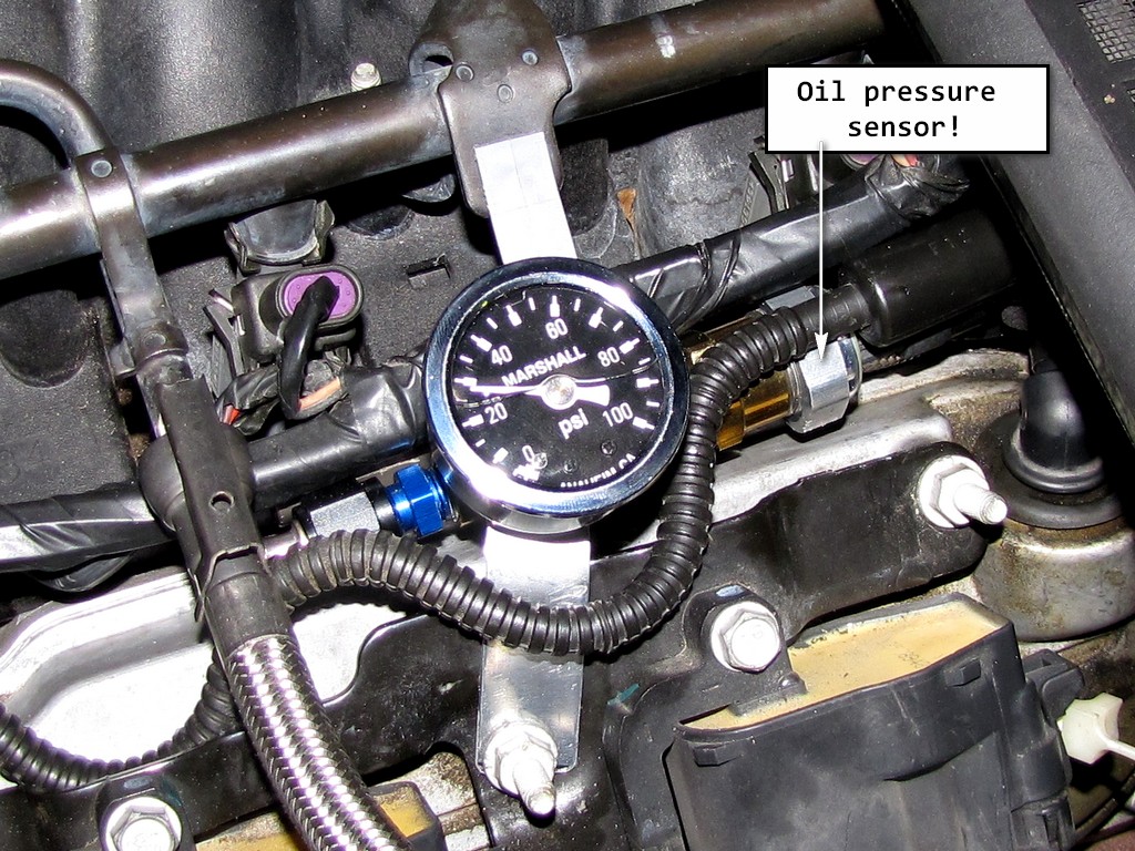
32. Remove the Engine Oil Pressure (EOP) sensor electrical connector.
Important
Clean the area around the EOP sensor before removal. This avoids debris from entering the engine.
33. Remove the EOP sensor. This is where you will use that 1-1/16 deep socket you saw at the beginning of this write-up. Notice how much oil has leaked around this area. If you allow that bad sensor to stay in the car long enough, yours will leak too.
At this point you have one of two routes to go. You can 1nstall the new EOP sensor, tightening the EOP sensor to 20 N•m (15 lb ft). Or, you can do the EOP relocate which I will go into more detail in step 36.
34. Install the fuel rail stop bracket.
34. Install the intake manifold bolts.
a) Tighten the intake manifold bolts a first pass in sequence to 5 N•m (44 lb in).
b)Tighten the intake manifold bolts a final pass in sequence to 10 N•m (89 lb in).
Here are some other tightening specifications that you will need during reassembly:
Tighten the PCV pipe strap nut to 12 N•m (106 lb in).
If removed, tighten the throttle body bolts to 10 N•m (89 lb in).
36. Now for those of us doing the relocate.
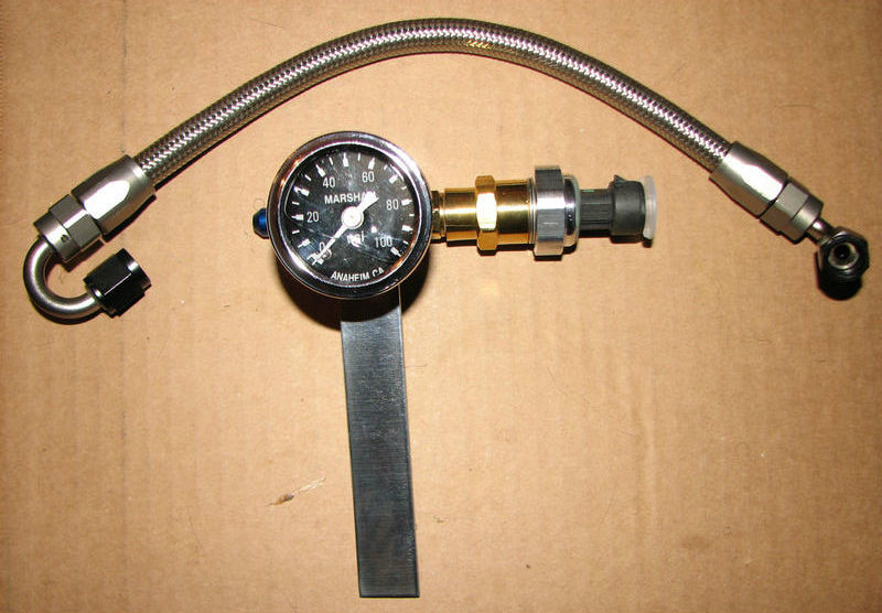
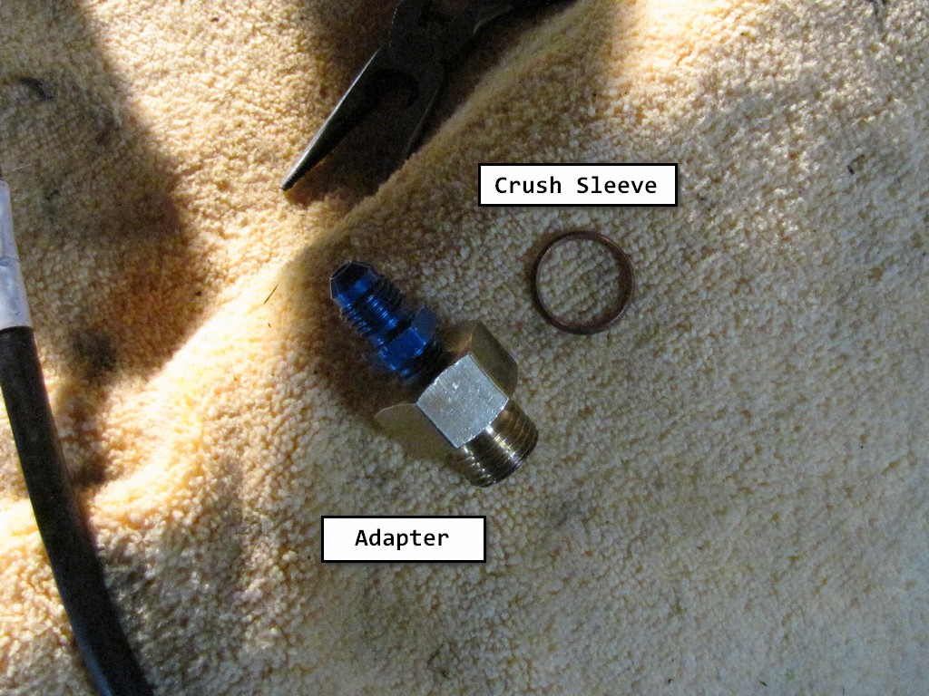
I got my relocation kit from DPE Corvettes. You can find cheaper kits on the web but they look just as they are priced, cheap. My kit is made from AN Adapter Fittings and stainless steel impregnated hose. A far cry from the plastic relocation kits I have seen. Your kit will come with instructions on how to install it. I will just touch on how it basically is installed. Check it out. The adapter that you will see later on does come with this kit.
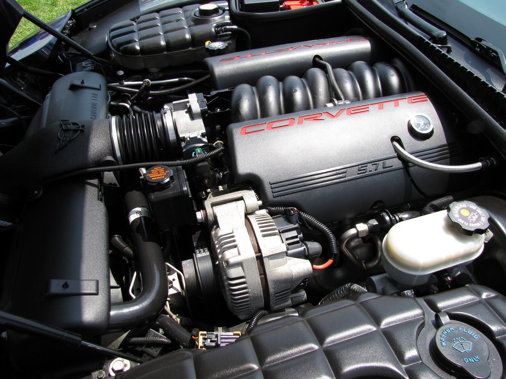
Before you install the new kit, take the time to clean up your engine. At this point, you can get to some hard to reach cracks and crevices. That's what I did, and now she looks much more presentable.
37. At this point, install the sensor adapter that comes with your kit. Don't forget to install the crush sleeve! Tighten to 20 N•m (15 lb ft).
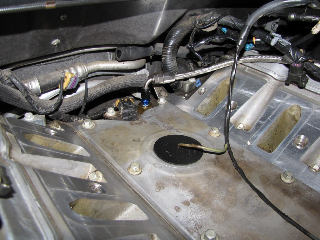
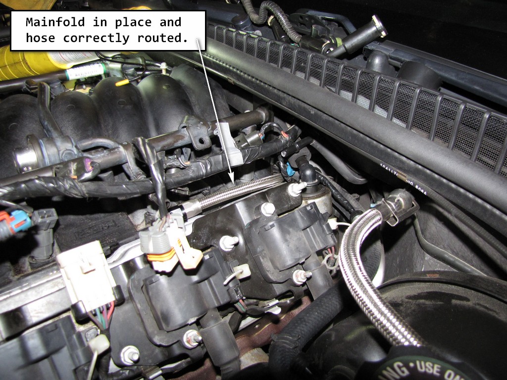
38. Install the stainless steel impregnated hose. Route the hose so that it will fit around the back, driver's side of the manifold.
Last edited by Junkman2008; Aug 28, 2012 at 08:00 AM.
At this point, you are ready to reassemble every thing. Just take it backwards from step 35. I will repost this information about the manifold bolts:
a) Tighten the intake manifold bolts a first pass in sequence to 5 N�m (44 lb in).
b)Tighten the intake manifold bolts a final pass in sequence to 10 N�m (89 lb in).
Here are some other tightening specifications that you will need during reassembly:
Tighten the PCV pipe strap nut to 12 N�m (106 lb in).
If removed, tighten the throttle body bolts to 10 N�m (89 lb in).
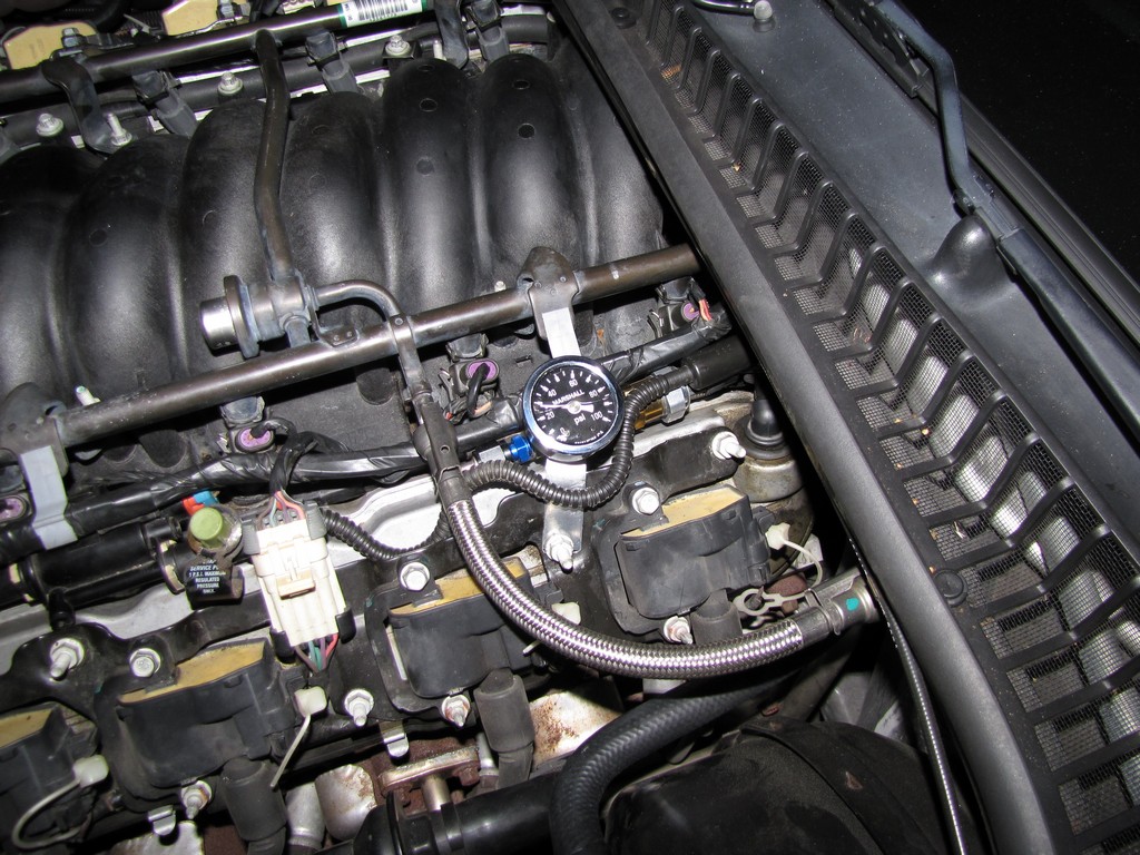
My dash is no longer lying to me:
Notice that I mounted my gauge using one of the screws from the coil packs. The cool thing about the setup is that the gauge under the hood is BEFORE the sensor so the reading it takes is always true. If the sensor goes bad again, That gauge will not be affected, only the dash gauge and DIC will read improperly.
The final product looks totally stock or professionally done. The gauge is 2" in size so you will need to drill a 2" hole in your fuel rail cover in order for it to fit over the gauge. As far as where you have to drill the hole will vary with each job as the location of your gauge can be slightly different than mine. It is somewhat of a trial and error guess, with error being the price of another fuel rail cover. That's $90 from the dealer (for ONE)! :surprised
I lucked up and found a used one for $30. Trial and error. It's a bitch sometimes.
Well there she is folks. The mother of all EOP sensor threads! It took me about 5 days to write this but I know a lot of guys who were scared to tackle it because of the unknown. If I can do it, anyone can because I don't know crap about working on cars. However, I can follow directions. That was one thing you learn to do when you become one of Uncle Sam's Misguided Children.
The Junkman
Last edited by Junkman2008; Aug 28, 2012 at 08:02 AM.
good write up but one point is that your picture where it says to connect fuel presure gauge is incorrect, you hook it up at the fuel rail, what you pointed at is the evap test port..
but excellent work and looks clean
Love the write up, my dad has this exact same problem on his Corvette so I want to show him how to do it. One question though, what was the point of draining the cooling system? When I changed my intake on a Camaro I did not have to do this.
good write up but one point is that your picture where it says to connect fuel presure gauge is incorrect, you hook it up at the fuel rail, what you pointed at is the evap test port..
but excellent work and looks clean
Thank you sir! I really appreciate you taking the time to read this and pointing out that discrepancy. I will fix that right away.
Is the point that I should pointing to at the end of the fuel rail by the throttle body, and has a cap on it that screws off?
Originally Posted by loyolacub68
Love the write up, my dad has this exact same problem on his Corvette so I want to show him how to do it. One question though, what was the point of draining the cooling system? When I changed my intake on a Camaro I did not have to do this.
Good question. When you disconnect the throttle body heater outlet hose, you'll lose about a gallon of antifreeze. For that reason, the service manual recommends that you drain the system. Remember, this is on a C5 Corvette so it may be different from the Camaro. The smell of Dex-Cool is enough to keep me from wanting that stuff spilled on my engine!
Thanks for checking this out guys. I really appreciate the feedback.
Thank you sir! I really appreciate you taking the time to read this and pointing out that discrepancy. I will fix that right away.
Is the point that I should pointing to at the end of the fuel rail by the throttle body, and has a cap on it that screws off?
Good question. When you disconnect the throttle body heater outlet hose, you'll lose about a gallon of antifreeze. For that reason, the service manual recommends that you drain the system. Remember, this is on a C5 Corvette so it may be different from the Camaro. The smell of Dex-Cool is enough to keep me from wanting that stuff spilled on my engine!
Thanks for checking this out guys. I really appreciate the feedback.
Ah I see what you mean here. I guess I didn't realize it last time because I did the TB bypass on mine.
this mod F bod friendly???? do vettes use a diff OPS???
The same applies to f-bodies as well. The sending unit in his pics looks different then ours, however, just do the mod exactly like it says only use your own sending unit and it will work out fine.
The same applies to f-bodies as well. The sending unit in his pics looks different then ours, however, just do the mod exactly like it says only use your own sending unit and it will work out fine.
The hose on the left in the pic is not the MAP sensor hose. It's for the brake booster. The plug unit on the right in the picture is the MAP sensor unit, it gets vacuum from the small port under it. The small vacuum line on the right is for the HVAC system. Just cleaning that up.
Nice work tho!
That's quite a write up! This will also be useful for the intake removal walk thru. I've found on the F-Bodies that if you rotate the back of the intake to the left (counter-clockwise) it helps to keep from snapping the OPS off. I never had a problem with it because I read SO much about it on here.
Gas Monkey Built a 6-Wheel Ferrari Testarossa With a Corvette LT4 Engine
Slideshow: The controversial Ferrari F6 swaps its original flat-12 for a Corvette Z06-derived LT4 V8 and sends power to four rear wheels through a custom-built drivetrain.
7 Most Reliable High-Performance Engines GM Has Ever Built
Slideshow:These GM engines didn't just make huge power, they survived abuse, boost, track days, and six-digit mileage with a reputation for refusing to quit.
6 Common C5 Corvette Failures and What's Involved In Repairing Them
Slideshow: From wobbling harmonic balancers to failed EBCMs, these are the issues that define long-term C5 ownership and what repairs typically involve.
Retro Modern Bandit Pontiac Trans AM Comes With Burt Reynolds' Autograph
Slideshow: A modern Camaro transformed into a retro icon, this limited-run "Bandit" build blends nostalgia with brute force in a way few revivals manage.
Top 10 Greatest Cadillac V Series Performance Models Ever, Ranked
Slideshow: Cadillac didn't just crash the high-performance luxury vehicle party, it showed up loud, supercharged, and occasionally a little unhinged...


 May 18, 2016, 06:06 PM


 )
)