
Went to junkyard to scope out my first LSx details
 03-05-2017, 10:47 AM
#41

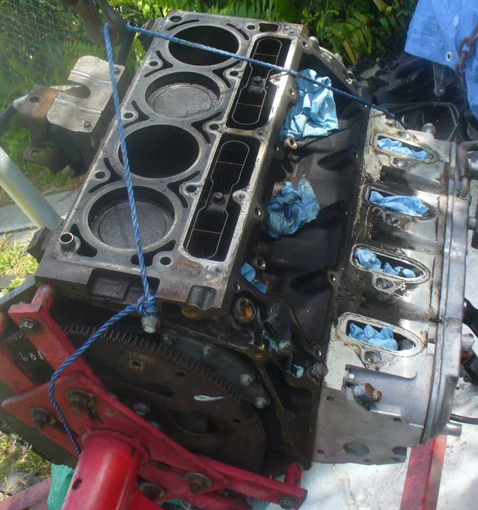
So we start out with a little pressure wash, a little degreasing, a little scrubbing down
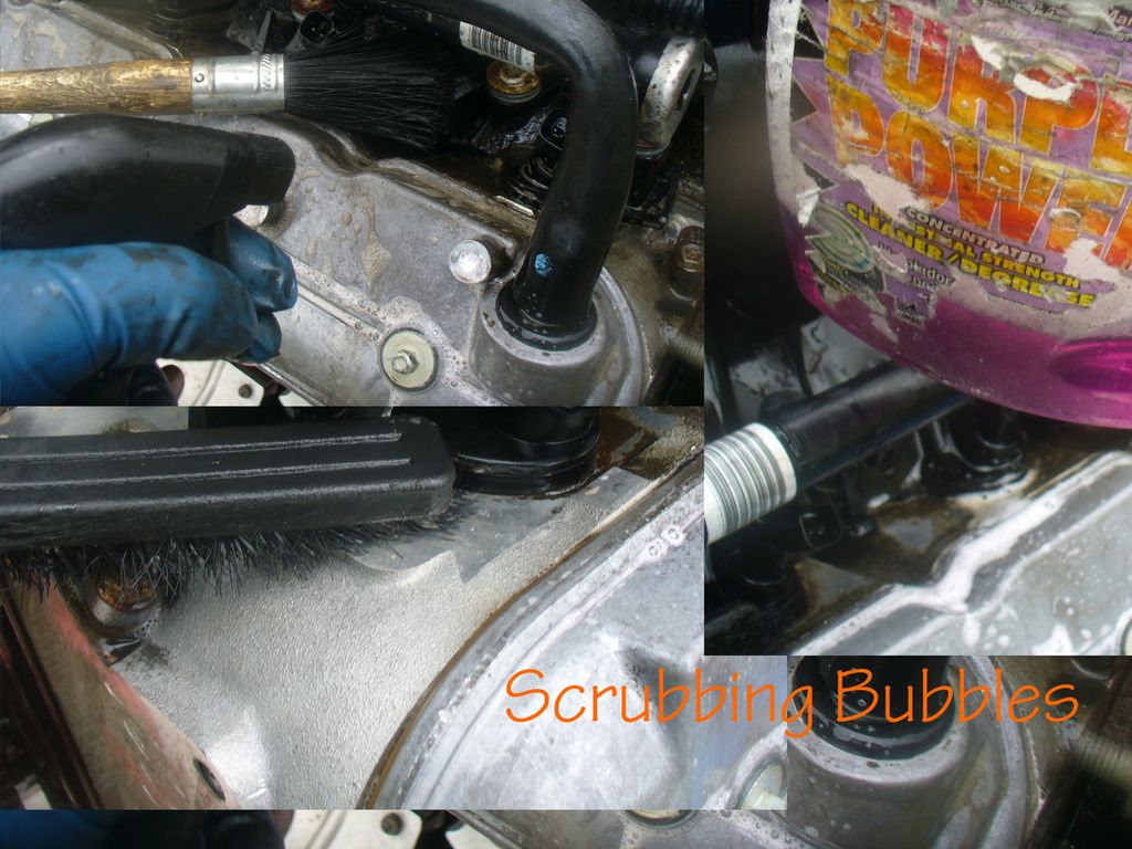
That knocked alot of loose dirt free, a good start.
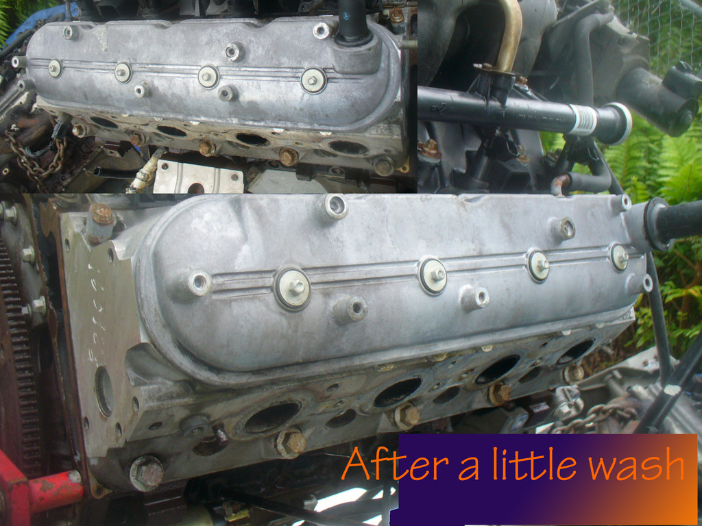
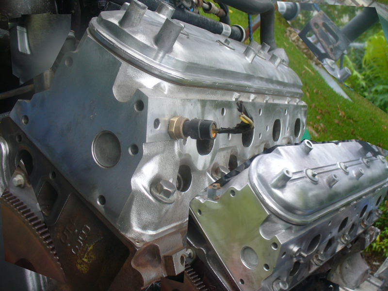
After a little wire wheel they really shined up nice, this is just so I can see what I am working with.
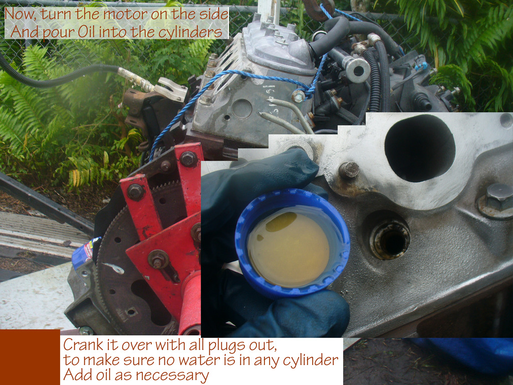
make sure to put oil in the cylinders after any kind of serious wash, and crank the motor over to make all the water come out of the cylinders. I keep doing this, oil, crank, oil, crank, until I see no more water coming out, and only oil.
I mixed up some of joe's special secret sauce
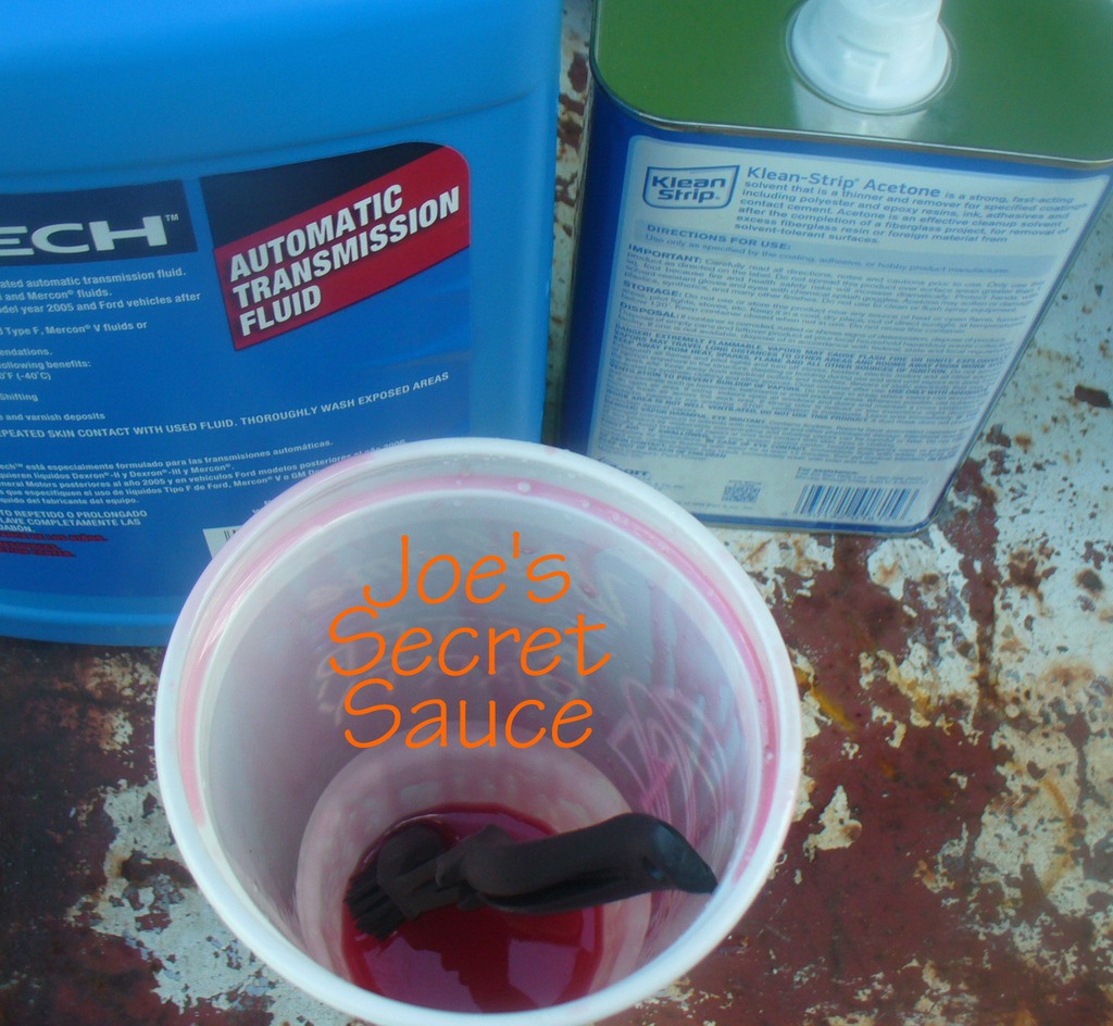
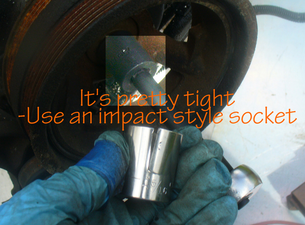
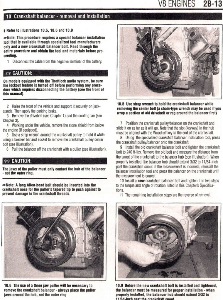
And realized just how tight that balancer bolt was, ha
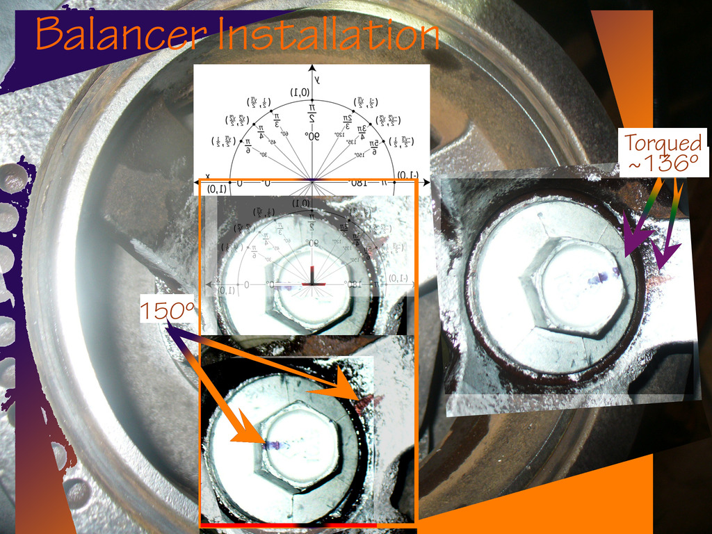
Cleaned up F-body balancer for installation,
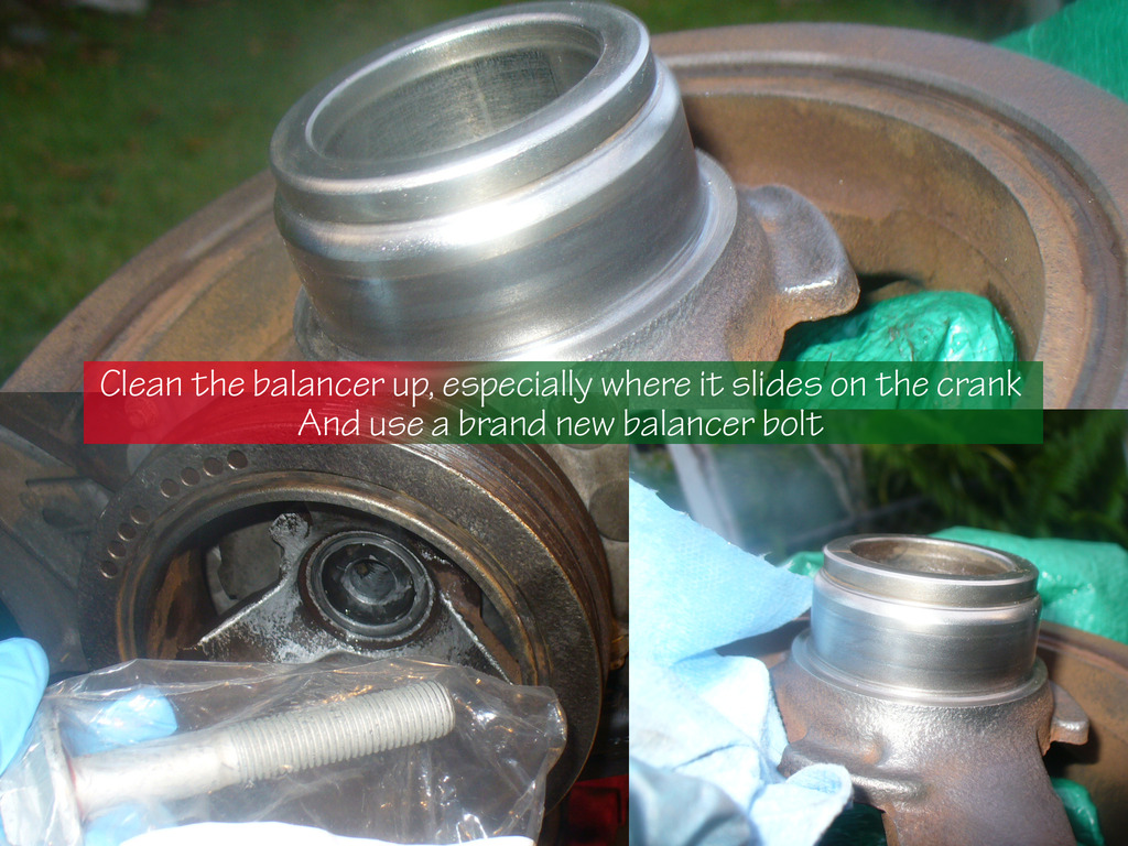
And torqued it with a new bolt
And then... major issue with the exhaust studs. After breaking a bunch of drill bits, and snapped several extractor bits, one of them even inside one of the studs (yikes), I had to dremel it into a fine dust powder... and so I decided to pull the head and bring it to a machine shop. This was 100% my fault for not waiting long enough with the secret sauce, it probably would have been fine if I was more patient... but thats not going to happen! Full Speed A-head!

That knocked alot of loose dirt free, a good start.

After a little wire wheel they really shined up nice, this is just so I can see what I am working with.

make sure to put oil in the cylinders after any kind of serious wash, and crank the motor over to make all the water come out of the cylinders. I keep doing this, oil, crank, oil, crank, until I see no more water coming out, and only oil.

I mixed up some of joe's special secret sauce

And realized just how tight that balancer bolt was, ha

Cleaned up F-body balancer for installation,

And torqued it with a new bolt

And then... major issue with the exhaust studs. After breaking a bunch of drill bits, and snapped several extractor bits, one of them even inside one of the studs (yikes), I had to dremel it into a fine dust powder... and so I decided to pull the head and bring it to a machine shop. This was 100% my fault for not waiting long enough with the secret sauce, it probably would have been fine if I was more patient... but thats not going to happen! Full Speed A-head!


 03-05-2017, 03:18 PM
#43
I will make a new thread for "build thread" activity, eventually. Right now I am still working on the engine "external engine" so I thought this place appropriate. If somebody searches the external engine section for one of the topics thats been covered here, they will miss the info in this thread if it is moved away. My concern is only for the individuals who come searching for these topics, not for myself or visibility.
Right now my biggest lesson and hard learned advice to those looking to buy an LSx engine and start a project for the first time, and use an OEM engine without pulling the head, is this:
1. check to see that all or most of the exhaust studs are able to loosen before you buy the engine, and they are not excessively rusty
2. check the compression of the engine
If you can do those two things before you buy an engine, you could skip ~30 hours of fooling around with exhaust studs and exchanging engines.
03-05-2017, 04:17 PM
#44

Saw a few post back you were talking fuel Delivery, don't know if you decided yet, but
the Dorman stuff looks like what I am going to try. This guy had some good info, check
out post #4 https://ls1tech.com/forums/conversio...ry-s-10-a.html
the Dorman stuff looks like what I am going to try. This guy had some good info, check
out post #4 https://ls1tech.com/forums/conversio...ry-s-10-a.html
03-05-2017, 05:34 PM
#45
Saw a few post back you were talking fuel Delivery, don't know if you decided yet, but
the Dorman stuff looks like what I am going to try. This guy had some good info, check
out post #4 https://ls1tech.com/forums/conversio...ry-s-10-a.html
the Dorman stuff looks like what I am going to try. This guy had some good info, check
out post #4 https://ls1tech.com/forums/conversio...ry-s-10-a.html
03-09-2017, 11:47 PM
#46
Some useful info I dug up for my re-assembly process. Hopefully pics in a day or two of that
Until then, with love
Stuff to do:
Clean the rocker arm pivot bolt threads with a wire brush
clean rocker arms, pivot *****, nuts or bolts, pushrods with solvent
check intake manifold to head with no gasket for weird space due to head decking
check rocker arms where they contact pushrod ends for damage galling roughspots etc
roll each pushrod for straightness
clean oil hole for pushrods
check rocker arm pivot bearings for binding and roughness
check spring installed height
apply moly base lubricant to rocker arm pivot and faces
check the camshaft lift with dial indicator
tap and clean the head bolt holes, use brake cleaner
Deck (head gasket surface) warpage limit 0.003 inch per 6 inches
'
Lobe life 5.3L from 2002:
Intake 0.268 inch
Exhaust 0.274 inch
extra info:
Main bearing oil clearance: V8 engines 0.0008 to 0.0021 inch
crankshaft end play 0.0015 to 0.007B inch
5.3L 98-02 Top compression ring end gap 0.010 to 0.016 inch
5.3L 98-02 Second compression ring end gap 0.017 to 0.027 inch
more stuff to do:
engine valley cover bolts 18ft lbs
Installation of pushrod/rocker:
lube lower end of pushrod and seat firmly into lifter
apply assembly lube to valve stem and upper pushrod end
apply clean engine oil to pivot shaft and bearing of rocker arm and install them loosely
rotate crank until number1 is TDC
3). With the number one piston is at TDC, tighten the intake
valve rocker arms for the Number 1, 3, 4, and 5 cylinders and the
exhaust rocker arms for the Number 1, 2, 7, and 8 cylinders. Tighten
each of the specified rocker arm bolts to the torque listed in this Chapter's
Specifications.
11 Rotate the crankshaft 360 degrees. Tighten the intake valve rocker
arms for the Number 2, 6, 7, and 8 cylinders and the exhaust rocker
arms for the Number 3, 4, 5, and 6 cylinders. Tighten each of the
rocker arm bolts to the torque listed in this Chapter's Specifications.
Intake manifold! : use medium strength threadlocking compound
head and deck:
10 The mating surfaces of the cylinder heads and block must be
perfectly clean when the heads are installed. Gasket removal solvents
are available at auto parts stores and may prove helpful.
11 Use a gasket scraper to remove all traces of carbon and old gasket
material, then wipe the mating surfaces with a cloth saturated with
lacquer thinner or acetone.
If there is oil on the mating surfaces when the heads are installed, the
gaskets may not seal correctly and leaks may develop. When working
on the block, use a vacuum cleaner to remove any debris that falls into
the cylinders.
12 Check the block and head mating surfaces for nicks, deep
scratches and other damage. If damage is slight, it can be removed with
emery cloth. If it is excessive, machining may be the only alternative.
13 Use a tap of the correct size to chase the threads in the head
bolt holes in the block. If a tap is not available, spray a liberal amount
of brake cleaner into each hole. Use compressed air (if available) to
remove the debris from the holes.
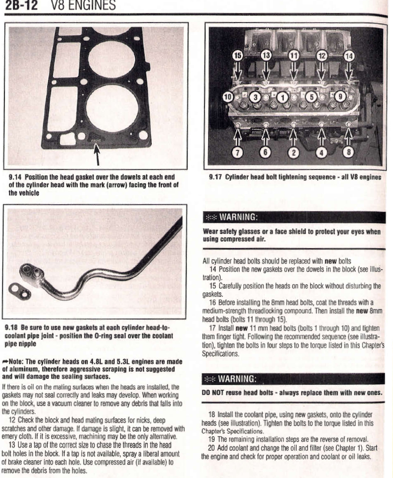
9.17 Cylinder head bolt tightening sequence - all V8 engines
**WARNING:
Wear safety glasses or a face shield to protect your eyes when
using compressed air.
All cylinder head bolts should be replaced with new bolts
14 Position the new gaskets over the dowels in the block (see illustration).
15 Carefully position the heads on the block without disturbing the
gaskets.
16 Before installing the 8mm head bolts, coat the threads with a
medium-strength thread locking compound. Then install the new 8mm
head bolts (bolts 11 through 15).
17 Install new 11 mm head bolts (bolts 1 through 1 0) and tighten
them finger tight. Following the recommended sequence (see illustration),
tighten the bolts in four steps to the torque listed in this Chapter's
Specifications.
Annnnd pictures always help
Knee deep in the jungle soil, run quickly to avoid quicksand
Until then, with love
Stuff to do:
Clean the rocker arm pivot bolt threads with a wire brush
clean rocker arms, pivot *****, nuts or bolts, pushrods with solvent
check intake manifold to head with no gasket for weird space due to head decking
check rocker arms where they contact pushrod ends for damage galling roughspots etc
roll each pushrod for straightness
clean oil hole for pushrods
check rocker arm pivot bearings for binding and roughness
check spring installed height
apply moly base lubricant to rocker arm pivot and faces
check the camshaft lift with dial indicator
tap and clean the head bolt holes, use brake cleaner
Deck (head gasket surface) warpage limit 0.003 inch per 6 inches
'
Lobe life 5.3L from 2002:
Intake 0.268 inch
Exhaust 0.274 inch
extra info:
Main bearing oil clearance: V8 engines 0.0008 to 0.0021 inch
crankshaft end play 0.0015 to 0.007B inch
5.3L 98-02 Top compression ring end gap 0.010 to 0.016 inch
5.3L 98-02 Second compression ring end gap 0.017 to 0.027 inch
more stuff to do:
engine valley cover bolts 18ft lbs
Installation of pushrod/rocker:
lube lower end of pushrod and seat firmly into lifter
apply assembly lube to valve stem and upper pushrod end
apply clean engine oil to pivot shaft and bearing of rocker arm and install them loosely
rotate crank until number1 is TDC
3). With the number one piston is at TDC, tighten the intake
valve rocker arms for the Number 1, 3, 4, and 5 cylinders and the
exhaust rocker arms for the Number 1, 2, 7, and 8 cylinders. Tighten
each of the specified rocker arm bolts to the torque listed in this Chapter's
Specifications.
11 Rotate the crankshaft 360 degrees. Tighten the intake valve rocker
arms for the Number 2, 6, 7, and 8 cylinders and the exhaust rocker
arms for the Number 3, 4, 5, and 6 cylinders. Tighten each of the
rocker arm bolts to the torque listed in this Chapter's Specifications.
Intake manifold! : use medium strength threadlocking compound
head and deck:
10 The mating surfaces of the cylinder heads and block must be
perfectly clean when the heads are installed. Gasket removal solvents
are available at auto parts stores and may prove helpful.
11 Use a gasket scraper to remove all traces of carbon and old gasket
material, then wipe the mating surfaces with a cloth saturated with
lacquer thinner or acetone.
If there is oil on the mating surfaces when the heads are installed, the
gaskets may not seal correctly and leaks may develop. When working
on the block, use a vacuum cleaner to remove any debris that falls into
the cylinders.
12 Check the block and head mating surfaces for nicks, deep
scratches and other damage. If damage is slight, it can be removed with
emery cloth. If it is excessive, machining may be the only alternative.
13 Use a tap of the correct size to chase the threads in the head
bolt holes in the block. If a tap is not available, spray a liberal amount
of brake cleaner into each hole. Use compressed air (if available) to
remove the debris from the holes.
9.17 Cylinder head bolt tightening sequence - all V8 engines
**WARNING:
Wear safety glasses or a face shield to protect your eyes when
using compressed air.
All cylinder head bolts should be replaced with new bolts
14 Position the new gaskets over the dowels in the block (see illustration).
15 Carefully position the heads on the block without disturbing the
gaskets.
16 Before installing the 8mm head bolts, coat the threads with a
medium-strength thread locking compound. Then install the new 8mm
head bolts (bolts 11 through 15).
17 Install new 11 mm head bolts (bolts 1 through 1 0) and tighten
them finger tight. Following the recommended sequence (see illustration),
tighten the bolts in four steps to the torque listed in this Chapter's
Specifications.
Annnnd pictures always help


Knee deep in the jungle soil, run quickly to avoid quicksand
03-15-2017, 01:37 PM
#47
Today is kinda day off so I will have a chance to upload a bunch of new pics of progress later,
at the moment I am still trying to tidy up the wiring, and I have a couple questions ATM if anyone feels like jumping in the water here...
Questions
1. The VSS on the 240sx normally goes from the VSS sensor -> cluster -> ECU
In the LSx engine, it goes from the VSS sensor -> ECU -> Cluster (It looks like, pin 50 is output speed from ECU)
So my question is, the speedo cluster in my 240sx dash is expecting a 2-wire signal from the VSS sensor, yet the LS ecu only outputs speed to a single wire. I am pretty sure if I take the VSS signal directly off the trans to the cluster like it wants, the speedo will read wrong. So how can I use the single wire (which I heard is customizable in the ECU sometimes) with my 2-wire cluster speedo input? Eh
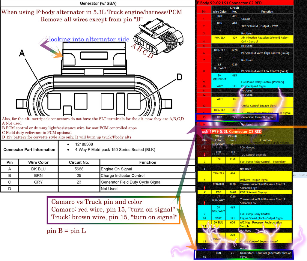
2. Alternator wiring! Q's (I am using 98-02 Fbody alternator with 5.3L truck harness/ECU)
I notice that "teh web" says I need to wire pin "B" (same as pin "L") To the ECU "generator/alternator turn on signal"
My questions are:
A: can I also wire this pin"B" to my dash-charge lamp indicator light? JW (just wonderin') I know the MIL will trip for low voltage also but I wanted my little dash light to work also lol
B: Will the PCM control the duty-cycle of the alternator? The truck alt uses pin"C" for "field duty" but the camaro Alt doesn't have a wire there in pin "C", and I can't seem to find a def. answer to that, JW
some interesting alternator info:
http://67-72chevytrucks.com/vboard/s...4&postcount=20
https://ls1tech.com/forums/conversio...l#post14588749
and a picture i make that shows the pins all around
at the moment I am still trying to tidy up the wiring, and I have a couple questions ATM if anyone feels like jumping in the water here...
Questions
1. The VSS on the 240sx normally goes from the VSS sensor -> cluster -> ECU
In the LSx engine, it goes from the VSS sensor -> ECU -> Cluster (It looks like, pin 50 is output speed from ECU)
So my question is, the speedo cluster in my 240sx dash is expecting a 2-wire signal from the VSS sensor, yet the LS ecu only outputs speed to a single wire. I am pretty sure if I take the VSS signal directly off the trans to the cluster like it wants, the speedo will read wrong. So how can I use the single wire (which I heard is customizable in the ECU sometimes) with my 2-wire cluster speedo input? Eh
2. Alternator wiring! Q's (I am using 98-02 Fbody alternator with 5.3L truck harness/ECU)
I notice that "teh web" says I need to wire pin "B" (same as pin "L") To the ECU "generator/alternator turn on signal"
My questions are:
A: can I also wire this pin"B" to my dash-charge lamp indicator light? JW (just wonderin') I know the MIL will trip for low voltage also but I wanted my little dash light to work also lol
B: Will the PCM control the duty-cycle of the alternator? The truck alt uses pin"C" for "field duty" but the camaro Alt doesn't have a wire there in pin "C", and I can't seem to find a def. answer to that, JW
some interesting alternator info:
http://67-72chevytrucks.com/vboard/s...4&postcount=20
https://ls1tech.com/forums/conversio...l#post14588749
and a picture i make that shows the pins all around


 03-16-2017, 11:53 AM
#49
Restricted User

[QUOTE=kingtal0n;19563365]Today is kinda day off so I will have a chance to upload a bunch of new pics of progress later,
at the moment I am still trying to tidy up the wiring, and I have a couple questions ATM if anyone feels like jumping in the water here...
Questions
1. The VSS on the 240sx normally goes from the VSS sensor -> cluster -> ECU
In the LSx engine, it goes from the VSS sensor -> ECU -> Cluster (It looks like, pin 50 is output speed from ECU)
So my question is, the speedo cluster in my 240sx dash is expecting a 2-wire signal from the VSS sensor, yet the LS ecu only outputs speed to a single wire. I am pretty sure if I take the VSS signal directly off the trans to the cluster like it wants, the speedo will read wrong. So how can I use the single wire (which I heard is customizable in the ECU sometimes) with my 2-wire cluster speedo input? Eh
2. Alternator wiring! Q's (I am using 98-02 Fbody alternator with 5.3L truck harness/ECU)
I notice that "teh web" says I need to wire pin "B" (same as pin "L") To the ECU "generator/alternator turn on signal"
My questions are:
A: can I also wire this pin"B" to my dash-charge lamp indicator light? JW (just wonderin') I know the MIL will trip for low voltage also but I wanted my little dash light to work also lol
B: Will the PCM control the duty-cycle of the alternator? The truck alt uses pin"C" for "field duty" but the camaro Alt doesn't have a wire there in pin "C", and I can't seem to find a def. answer to that, JW
1. https://ekwang.wordpress.com/2012/12...0sx-s13-speed/
2A: Yes, you can wire it to your charge indicator. This is how its done most of the time.
2B: Don't overcomplicate it. The alternator can be ran as a 1-wire setup using Pin B. It needs 12v from an ignition source plus ~470 OHMs of resistance, and it will put the alternator at ~90% duty cycle and give you just over 14V. This can either be done by wiring it through the charge indicator lamp, or grabbing a 10 cent 470 ohm resistor and putting it inline with a 12v ignition source going to pin B on the alternator connector.
03-16-2017, 05:32 PM
#51
2B: Don't overcomplicate it. The alternator can be ran as a 1-wire setup using Pin B. It needs 12v from an ignition source plus ~470 OHMs of resistance, and it will put the alternator at ~90% duty cycle and give you just over 14V. This can either be done by wiring it through the charge indicator lamp, or grabbing a 10 cent 470 ohm resistor and putting it inline with a 12v ignition source going to pin B on the alternator connector.
03-18-2017, 01:46 AM
#54
Teching In

Join Date: Feb 2017
Posts: 1
Likes: 0
Received 0 Likes
on
0 Posts
Nice job keeping track of everything, i was so confused on what to get when pulling my first lsx swap. If you want to verify wether its a 5.3 or 4.8 just look the vin up on google it should give you info on the truck and tell you specs.
03-19-2017, 09:24 PM
#55
This is 3-12-17
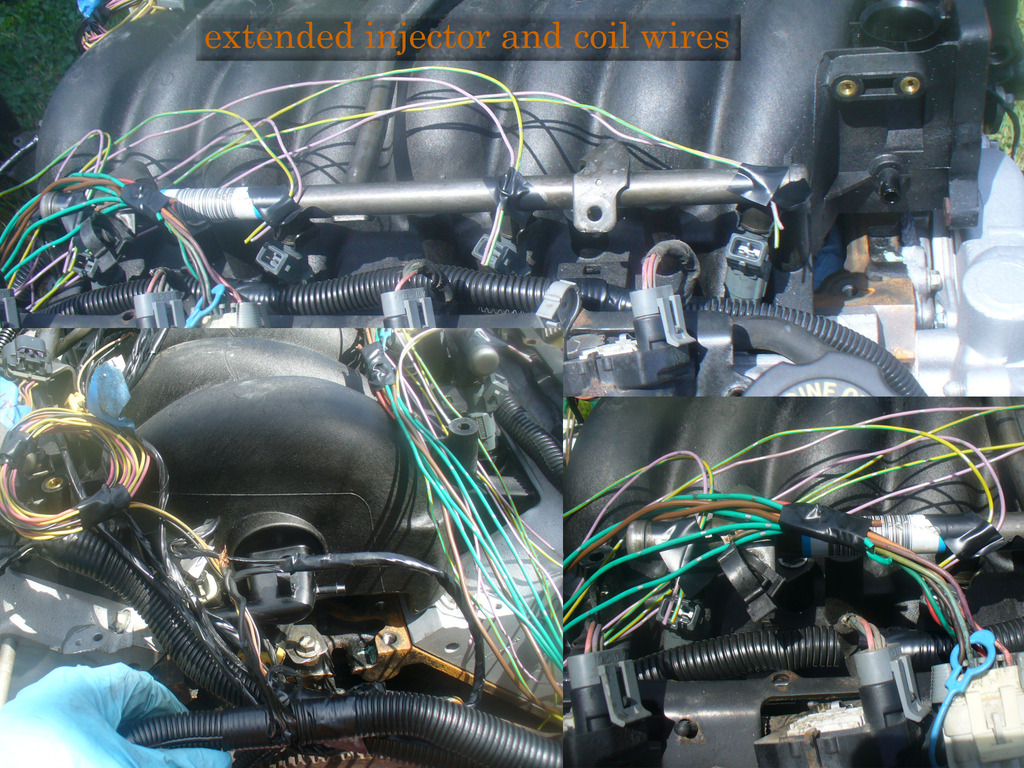
I had a lul in progress from 3-13 to 3-15 while I fooled around more with the harness. I had a couple concerns about the factory switched 12V feeding all of the injectors/coils so I wanted to something a little more robust, at least until I can test the amperage draw of the engine running. I also had to re-wire the injectors and coils to move them opposite sides, for some reason when I got the harness on the engine the way it seemed to want to fit into the 240sx (like an OEM 240sx harness) the cylinder #2 side was on the #1 side and the others were too short to even reach the other, wrong side.
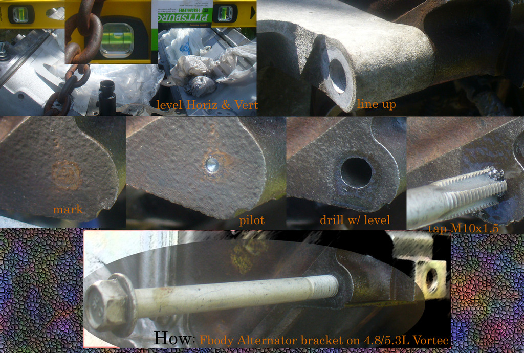
Begin with alt bracket, if you search on the forum there are other members who have done this and show exactly how, I followed their directions with good results, although I know I wasn't perfect because I could tell the bracket wasn't absolutely perfect by the way it torqued down:
here is some of the wiring example I had to do
I compared LS6 to 5.3L valley cover gaskets out of curiosity
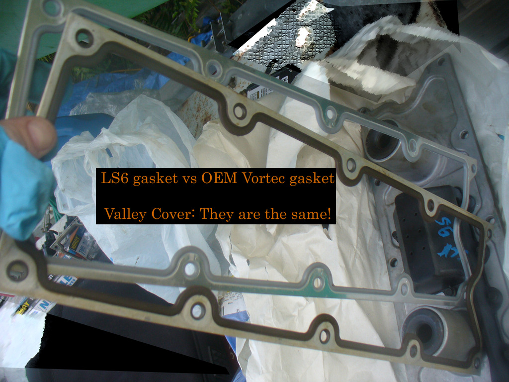
Decided to use the truck valley cover after all. The LS6 has a PCV port, or breather, it seems, that runs to the back of the engine. The last thing I want is another hole in the engine somewhere hard to reach.

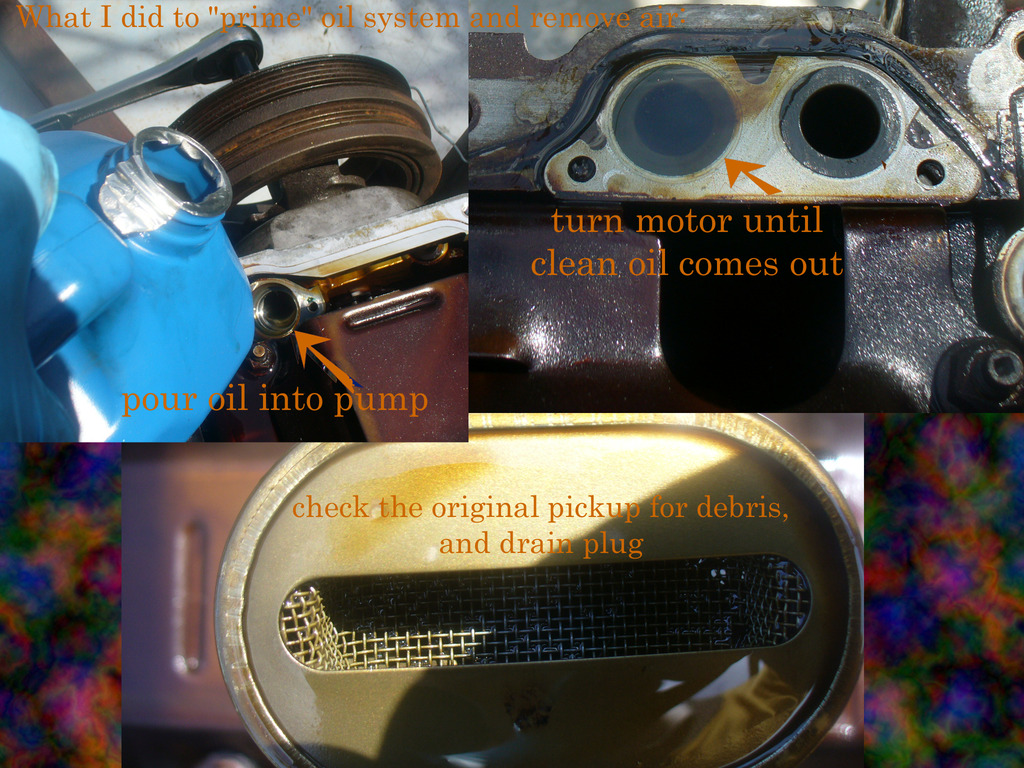
I wanted to make sure there was no air if possible in the oil system, so I turned it over and watched the air come out of the other side while pouring into the oil pump. I am not sure that was important or necessary; I just figured I would do it anyways.
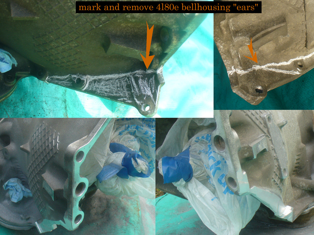
had to cut the ears off the 4l80e, I used a pretty big grinder to do this. It made a huge mess! Be sure to triple wrap the input shaft, and the dipstick port, and all of the electronics! Then, take a shower! haha there was aluminum in my ears...
Engine should be running in a couple days
I had a lul in progress from 3-13 to 3-15 while I fooled around more with the harness. I had a couple concerns about the factory switched 12V feeding all of the injectors/coils so I wanted to something a little more robust, at least until I can test the amperage draw of the engine running. I also had to re-wire the injectors and coils to move them opposite sides, for some reason when I got the harness on the engine the way it seemed to want to fit into the 240sx (like an OEM 240sx harness) the cylinder #2 side was on the #1 side and the others were too short to even reach the other, wrong side.
Begin with alt bracket, if you search on the forum there are other members who have done this and show exactly how, I followed their directions with good results, although I know I wasn't perfect because I could tell the bracket wasn't absolutely perfect by the way it torqued down:

here is some of the wiring example I had to do

I compared LS6 to 5.3L valley cover gaskets out of curiosity

Decided to use the truck valley cover after all. The LS6 has a PCV port, or breather, it seems, that runs to the back of the engine. The last thing I want is another hole in the engine somewhere hard to reach.

I wanted to make sure there was no air if possible in the oil system, so I turned it over and watched the air come out of the other side while pouring into the oil pump. I am not sure that was important or necessary; I just figured I would do it anyways.

had to cut the ears off the 4l80e, I used a pretty big grinder to do this. It made a huge mess! Be sure to triple wrap the input shaft, and the dipstick port, and all of the electronics! Then, take a shower! haha there was aluminum in my ears...

Engine should be running in a couple days
03-22-2017, 12:00 AM
#56
This was 3-17-17
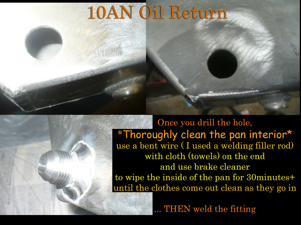
Pan fittings installed
Booted the computer up at home. First, segment swapped a DBC engine/DTC portion, then segment swapped a 4l80 trans sections into my native OS, then upgraded to the 2-bar map. So far invested 2 credits. I backed up the original OS and tune files so I can start over if necessary. I spent most of the day dealing with the computer and trying different things with varied results. HPtuners is new to me so it was and is still a learning curve.
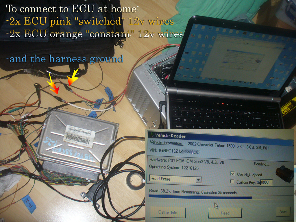
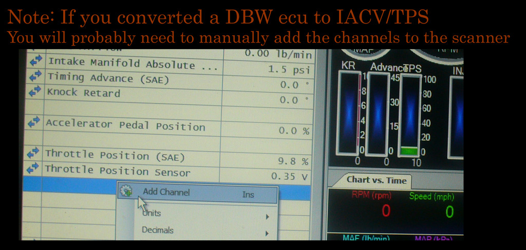
When I loaded the scanner to check the TPS/MAP/IACV, at first it didn't show the TPS, and I got worried that it wasn't working. After a while I figured out why it looked like it wasn't working:
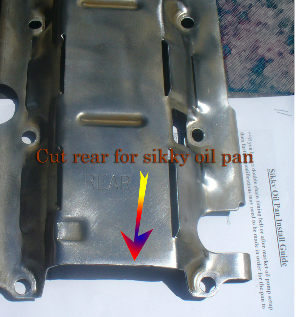
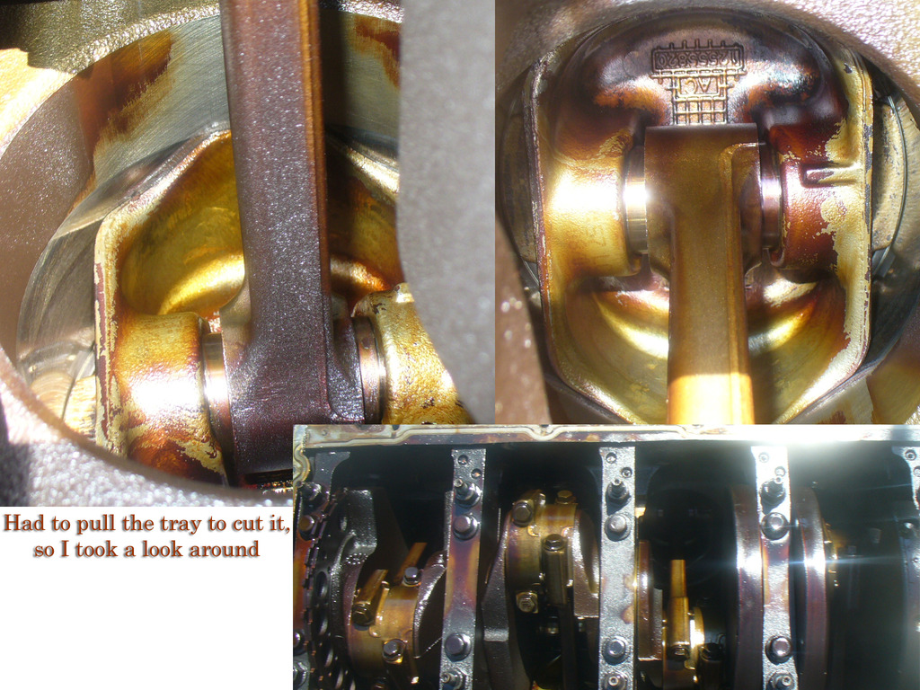
On to the engine, sikky says ya gota cut the rear section of the windage tray off. There doesn't seem to be any interference with the pan, so I have to guess this is for oil flow reasons.
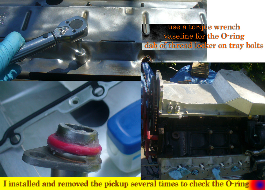
I was really skeptical of the O-ring. So many have torns theirs. I actually wasn't comfortable using this large red one shown in the picture, it was too tight of a fit, and after I tried installing and removing it a couple times I did manage to tear it. I was not surprised; I think some O-rings are better than others as far as fitment goes, or there might be a trick to the installation I haven't figured out yet. I wound up using the one sikky provided, which was slightly larger inside diameter, but seemed to fit snugly also.
update: Indeed, there are different O-rings! I found out after doing a little research that if the pickup tube has an indentation, you would want to use the larger thicker O-ring like the one in my picture. The O-ring that came out of my engine was green, I have no idea which Style O-ring it was anymore but I did keep it so I will be getting a pic of it soon. The one that came with the sikky kit was "blue", and thin design. And that is the one I wound up using (because I tore the red one trying to fit it in there, by coincidence of course, I didn't know at the time it was the wrong O-ring for the sikky pickup tube).
Got a look inside the motor since i had to pull the tray anyways
At this point I mostly finished the trans mounts, and I was waiting on the driveshaft (I got it back today) to see if my best guess was close enough for the pinion angle to be correct. I hope to investigate tomorrow but it is supposed to rain, so it might have to wait until friday. Most of the threads I read about this swap involve "hammering the trans tunnel" however, I see no reason to do this yet, unless the trans needs to be raised alot more to get the right pinion angle. It barely fits but it definitely seems to fit without having to hammer a single thing. In fact even the hammering I did around the bellhousing seemed like overkill, there is plenty of room all around, even for those "ears" I took off of the trans.
I am doing all of this in the grass/mud but I am able to put down a plate if I need to pick something heavy up (like a car or engine). I think I will do one more post that leads into the trans/wiring but then that will be it for this "external engine" thread, I will make a new thread for "assembly" of the drivetrain in an appropriate location.
Pan fittings installed

Booted the computer up at home. First, segment swapped a DBC engine/DTC portion, then segment swapped a 4l80 trans sections into my native OS, then upgraded to the 2-bar map. So far invested 2 credits. I backed up the original OS and tune files so I can start over if necessary. I spent most of the day dealing with the computer and trying different things with varied results. HPtuners is new to me so it was and is still a learning curve.

When I loaded the scanner to check the TPS/MAP/IACV, at first it didn't show the TPS, and I got worried that it wasn't working. After a while I figured out why it looked like it wasn't working:

On to the engine, sikky says ya gota cut the rear section of the windage tray off. There doesn't seem to be any interference with the pan, so I have to guess this is for oil flow reasons.

I was really skeptical of the O-ring. So many have torns theirs. I actually wasn't comfortable using this large red one shown in the picture, it was too tight of a fit, and after I tried installing and removing it a couple times I did manage to tear it. I was not surprised; I think some O-rings are better than others as far as fitment goes, or there might be a trick to the installation I haven't figured out yet. I wound up using the one sikky provided, which was slightly larger inside diameter, but seemed to fit snugly also.
update: Indeed, there are different O-rings! I found out after doing a little research that if the pickup tube has an indentation, you would want to use the larger thicker O-ring like the one in my picture. The O-ring that came out of my engine was green, I have no idea which Style O-ring it was anymore but I did keep it so I will be getting a pic of it soon. The one that came with the sikky kit was "blue", and thin design. And that is the one I wound up using (because I tore the red one trying to fit it in there, by coincidence of course, I didn't know at the time it was the wrong O-ring for the sikky pickup tube).

Got a look inside the motor since i had to pull the tray anyways

At this point I mostly finished the trans mounts, and I was waiting on the driveshaft (I got it back today) to see if my best guess was close enough for the pinion angle to be correct. I hope to investigate tomorrow but it is supposed to rain, so it might have to wait until friday. Most of the threads I read about this swap involve "hammering the trans tunnel" however, I see no reason to do this yet, unless the trans needs to be raised alot more to get the right pinion angle. It barely fits but it definitely seems to fit without having to hammer a single thing. In fact even the hammering I did around the bellhousing seemed like overkill, there is plenty of room all around, even for those "ears" I took off of the trans.
I am doing all of this in the grass/mud but I am able to put down a plate if I need to pick something heavy up (like a car or engine). I think I will do one more post that leads into the trans/wiring but then that will be it for this "external engine" thread, I will make a new thread for "assembly" of the drivetrain in an appropriate location.
Last edited by kingtal0n; 03-24-2017 at 11:07 PM.
03-24-2017, 09:28 PM
#57
Alright, so I was hoping the next post would be a video of the engine running and "this concludes our engine/external" thread sort of thing, but it isn't, I actually think I have an issue with the engine I wanted to ask the experts on LStech.
So here is whats going on. I pulled the plugs and crank the motor a little bit, and oil came rushing out of the 10AN remote oil filter line like I expected. I put the filter on, and cranked the engine some more (about 50-60 revolutions) and I still don't see any oil coming out of the pushrods, and the oil light in the car (which I am pretty sure I wired up correctly) isn't going out, which is my main huge warning sign. I pulled the filter back off and it seems plenty full of oil so I know it is going in there. I cranked it some more and still the light doesn't go off.
So my question is, how much cranking is normally necessary to get the oil light (3psi?) to go off in the car, and how much cranking is necessary for the rockers to get oil?
And another question, if I install an oil pressure gauge onto the oil filter OUTLET (return to pan/engine) will it show me just as much oil pressure as the INLET would? Or is there some kind of bypass prior to the filter (I think so?) that is full pressure, whereas the filter is not throwing large pressure post filtration... I hope I worded that well enough.
Basically I stopped right there and I am going to get an oil pressure gauge on it before going further. The gauge will be pre-filter on the oil filter outlet from the pan, in the line going to the filter but before the filter. I should see 40~psi of oil pressure during cranking I thought?
Where could I have made a mistake, does anybody see anything? I had the motor upside down, does that make a difference? I even 'primed' it by pouring oil into the oil lines before installing the filter.
03-24-2017, 09:36 PM
#58
TECH Senior Member
iTrader: (7)
When I first fired up the GTO, I unhooked my coils, took the oil filter off, and cranked it over until oil dripped out of the filter pad. Took maybe 20 seconds. With my Cougar, I didn't bother. Fire in the hole. Oil pressure shot up to 40 psi instantly.
Andrew
Andrew
03-24-2017, 10:24 PM
#59
I found this thread:
https://ls1tech.com/forums/generatio...schematic.html
So it seems either,
A: bad/walked cam bearing
B: improper oil pan gasket / install
C: I am just being too cautious and everything is fine
D: and of course, always could be a torn O-ring or blockage/debris I suppose
I am more or less ruling out the barbell and similar galley plugs as this engine is 100% OEM as far as I know, with mileage, and good compression. I know anything is possible, not ruling them out 100%, just saying that it is far more likely there was an issue with my gasket install (meh) Or a cam bearing (??!) or some debris maybe, or the fact it sat for years before I got it perhaps. Or the O-ring. sigh, always the Oring. I want to place a bet that 51% chance it really is the silly O-ring I used.
So here is what I found out so far. There are different O-rings. I used the "thin" design, a blue O-ring that came with the sikky kit, for the straight Oil pickup. SO I think I am good there. I am not sure if my original pickup was using "thick" or "thin" style O-rings. I will post a pic.
picture of the OEM pickup tube and O-ring:
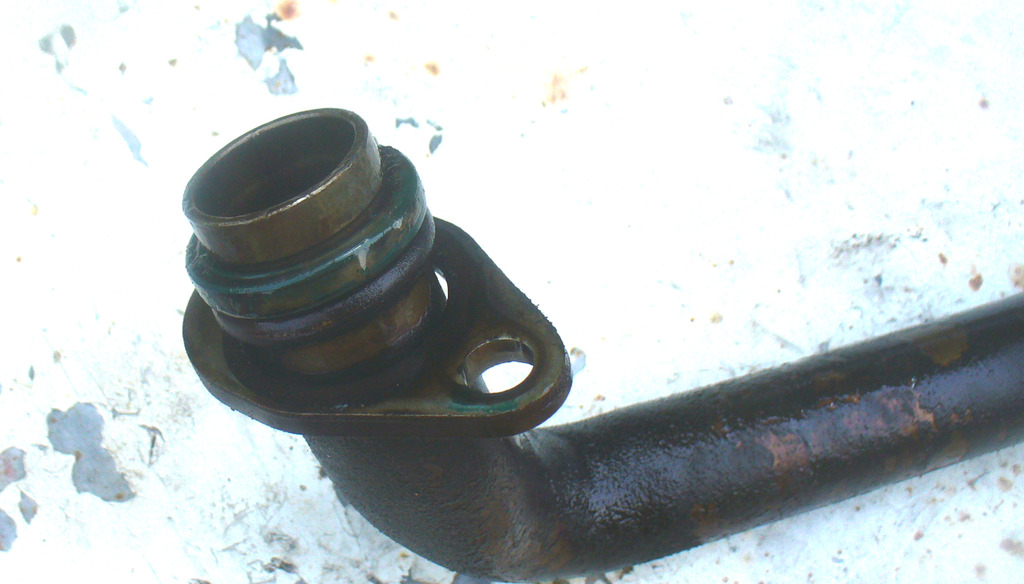
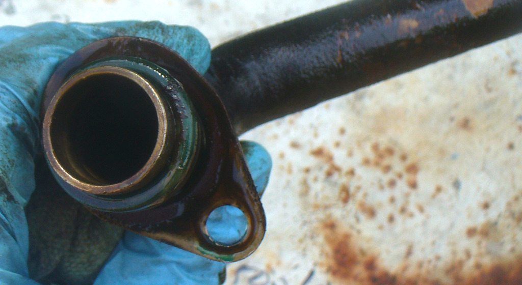
To me, it looks like a straight design, thinner Oring style.
I still have it, and I will measure it. Although at this point it really doesn't matter (I was just curious) because I definitely used the thin style O-ring on a straight pickup tube in the engine.
Last edited by kingtal0n; 03-24-2017 at 11:11 PM.
03-25-2017, 10:51 AM
#60
Sikky rep thinks it is an oil pump issue. my question is, if the pump is bad, wasn't the engine run in the original vehicle with a bad pump also? That sounds terrible.
From sikky:
"Yes so we have seen junk yard engines that came out of running cars get swapped in and have same low oil pressure issue. We assumed just like you that there was no way it could be the pump because supposedly it was running prior. After tearing everything apart we found the pump was the problem. This same thing has happened several times over the many years we have been doing these swaps. 10+ years to be exact. If you checked all the obvious stuff and it all checks out than this is likely your issue. " -Sikky rep
I suppose the only thing to do is buy an oil pump and have it handy.
update: i bought an oil pump and a new balancer bolt (sigh).
My next question is, will I be able to re-use the existing timing cover gasket materials?
Biggest regret is, I really, really, really sealed up that oil pan. I mean, I really sealed it up. I really did. Its going to really suck pulling it back off. maniacal laughters ensue....
plans as of now:
remove engine/trans. Cut trans tunnel so the 4l80e can be at 0* just like the IRS differential. Weld plate to the under-side of the car for a new trans-mount bracket location. Change oil pump in engine. step 3: profit
If the mods dont mind I want to keep this thread going since technically I am still in external engine diagnostics/procedures. Or else I can split everything up (trans work / computer work) into other threads. If I dont get any response I will just assume nobody cares and do whatever I can to make the info easy to consolidate.
Last edited by kingtal0n; 03-25-2017 at 01:40 PM.