


Proper front cover install using correct tools pics inside

Thread Starter
9 Second Club
iTrader: (23)
Joined: Oct 2002
Posts: 1,150
Likes: 1
From: Mastic Long Island N.Y.
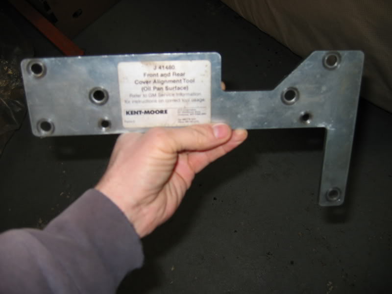
This may seems a bit simple for some of you guys who have done this multiple times so this is really just for those who have not. I'm sure some of you guys have heard of the Kent Moore tools used for LS series motors. Here are some pics below of what tools are used where and you will see why it is important.
First is the cover alignment tool this can be used for both the front and rear covers. You just use a different set of holes for the front or the rear covers depending on your needs.
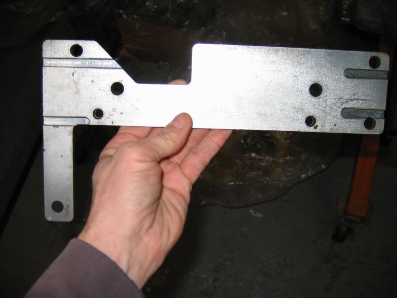
Here is the other side of the plate you can see the machined slots in the surface. These provide room for the front or rear gaskets tabs that protrude a bit below the oilpan surface of the block.
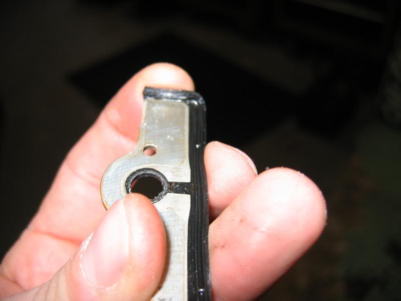
Here is a picture showing the rubber "tab" on the front cover gasket that those slots are machined for. I am bending the rubber tab here
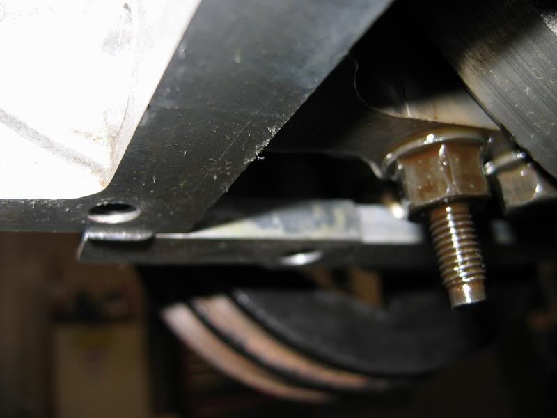
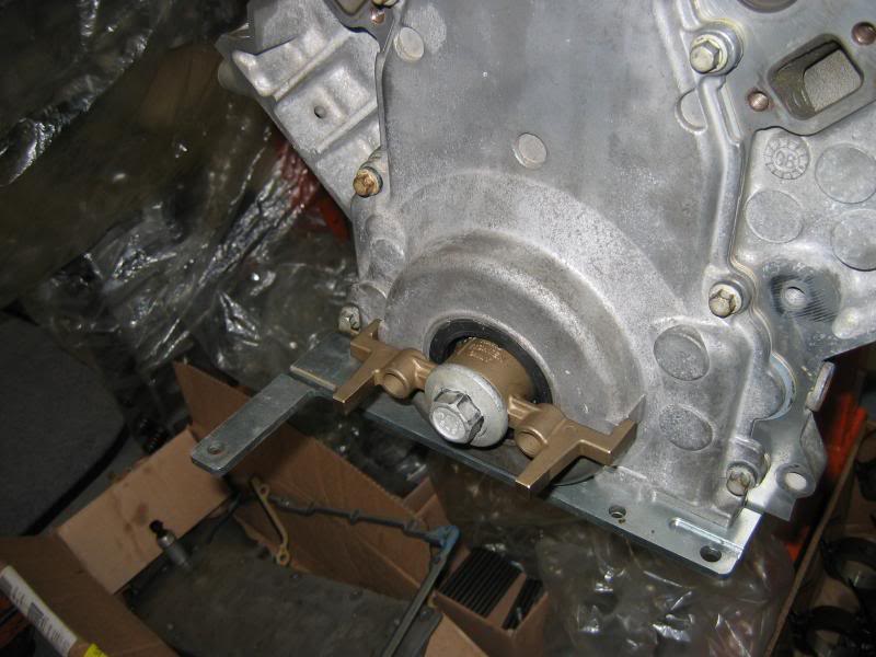
Here the plate is installed for front cover installation
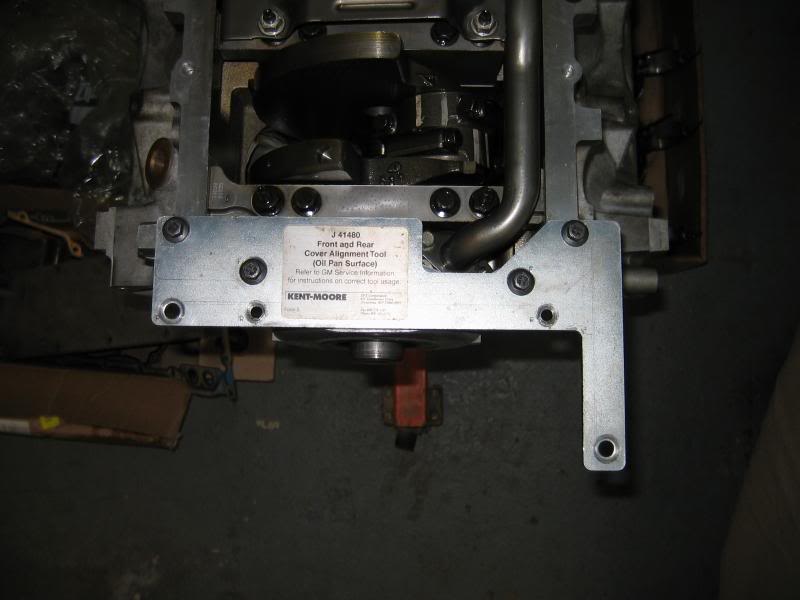
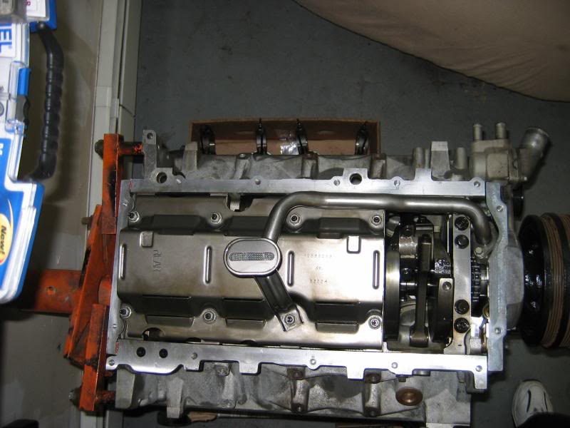
It gets fatened to the oilpan /block surface 2 bolts into the block and 2 into the bottom of the front cover. This ensures the bottom of the front cover is nice and flush with the blocks surface. This will ensure the oilpan has a flat surface to mate up with as the oilpan's footprint covers both front and rear covers when viewed from directly underneath. Below is a pic of the block with both front and rear covers installed. You can see the footprint the oilpan covers here. The oilpan actually ties the lower end of this motor together and is a part of the structural integrity of these motors.
Below is a picture showing the inside of an LS2 cover with the plate bolted to it so you can more easily see where those machined slots reside.
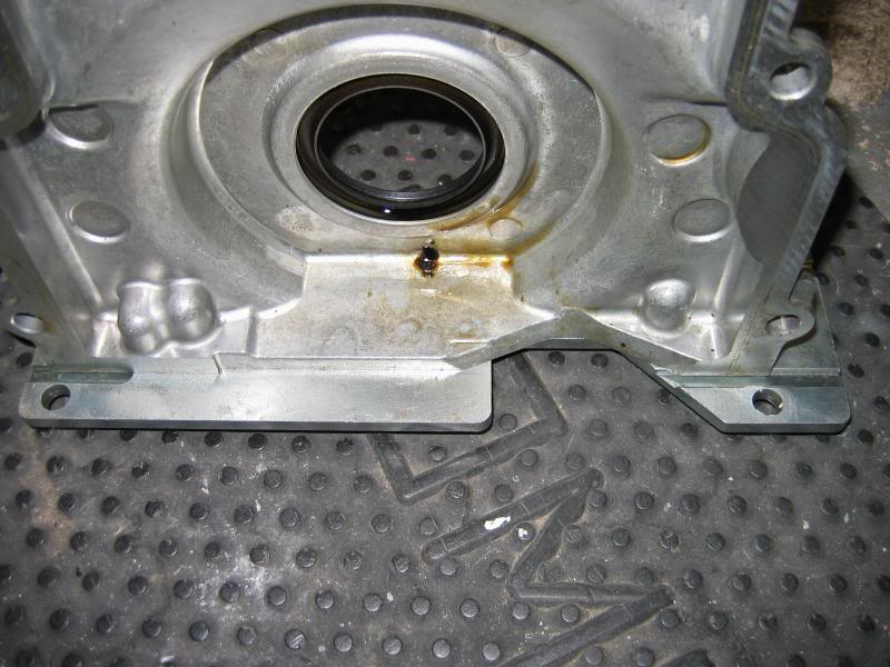
Finally below is a picture of the front cover installed and it shows the tab that sticks out beyond the surface and the is the purpose of the slots in the plate.
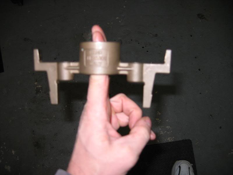
That plate orients the cover up and down now the cover needs to be set correctly side to side. It needs to be centered around the crank snout so the front seal can do it's job. Here is a pic with me pointing out the 2 bosses that are cast into the front covers design. Some of you guys probably never knew they even had a purpose (I did'nt until I installed a front cover).
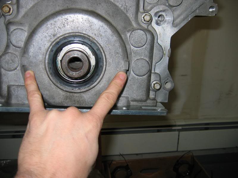
Here is a picture of the tool that will center the cover radially around the crank snout using the 2 bosses in the picture above. It just slides right onto the crank snout where you see my fingers sticking thru it.
And here it is installed on the cover using the crank pully bolt to seat into place.
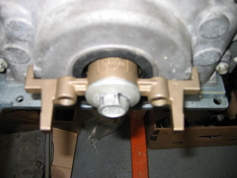
Here is one more pic notice the 2 (of the 4) machined slots are under the front cover now and are providing a space for the front cover gasket to stick below the block/covers surface. This part of the gasket I am talking about are just small flexible rubber tabs and dont stick out very much.
When the cover is all in place the bolts get torqued down and the front cover is in it's correct place. Now I'm sure some guys may not bother with the tools at all and have no issue's. I have access to these tools and it does not cost me anything so why not use them. I just thought i'd share this process for anybody who has heard about these tools and was curious.
First is the cover alignment tool this can be used for both the front and rear covers. You just use a different set of holes for the front or the rear covers depending on your needs.
Here is the other side of the plate you can see the machined slots in the surface. These provide room for the front or rear gaskets tabs that protrude a bit below the oilpan surface of the block.
Here is a picture showing the rubber "tab" on the front cover gasket that those slots are machined for. I am bending the rubber tab here
Here the plate is installed for front cover installation
It gets fatened to the oilpan /block surface 2 bolts into the block and 2 into the bottom of the front cover. This ensures the bottom of the front cover is nice and flush with the blocks surface. This will ensure the oilpan has a flat surface to mate up with as the oilpan's footprint covers both front and rear covers when viewed from directly underneath. Below is a pic of the block with both front and rear covers installed. You can see the footprint the oilpan covers here. The oilpan actually ties the lower end of this motor together and is a part of the structural integrity of these motors.
Below is a picture showing the inside of an LS2 cover with the plate bolted to it so you can more easily see where those machined slots reside.
Finally below is a picture of the front cover installed and it shows the tab that sticks out beyond the surface and the is the purpose of the slots in the plate.
That plate orients the cover up and down now the cover needs to be set correctly side to side. It needs to be centered around the crank snout so the front seal can do it's job. Here is a pic with me pointing out the 2 bosses that are cast into the front covers design. Some of you guys probably never knew they even had a purpose (I did'nt until I installed a front cover).
Here is a picture of the tool that will center the cover radially around the crank snout using the 2 bosses in the picture above. It just slides right onto the crank snout where you see my fingers sticking thru it.
And here it is installed on the cover using the crank pully bolt to seat into place.
Here is one more pic notice the 2 (of the 4) machined slots are under the front cover now and are providing a space for the front cover gasket to stick below the block/covers surface. This part of the gasket I am talking about are just small flexible rubber tabs and dont stick out very much.
When the cover is all in place the bolts get torqued down and the front cover is in it's correct place. Now I'm sure some guys may not bother with the tools at all and have no issue's. I have access to these tools and it does not cost me anything so why not use them. I just thought i'd share this process for anybody who has heard about these tools and was curious.
Last edited by JFM-jr; Jan 4, 2009 at 05:33 PM.
i install the balancer in the front to align the front cover-while it is nice to have the kent moore tools, i have paid more for some of them than a used engine-build a 4l80e and price them out, lol-never thought pieces of plastic were worth so much
Since I still had the pan on, I used a very finely graduated 6" metal rule to center the shaft within the seal housing. I used the OD of the seal rather than the ID since the ID of the seal isn't necessarily round.
Nice photo's, where did you get the tools?
Nice photo's, where did you get the tools?
Trending Topics
LS1 Tech Stories
The Best V8 Stories One Small Block at Time

Topdon ONE vs. Artidiag 800 BT2: Which is the Diagnostic Tablet For You?
Pouria Savadkouei
Gas Monkey Built a 6-Wheel Ferrari Testarossa With a Corvette LT4 Engine
Verdad Gallardo
7 Most Reliable High-Performance Engines GM Has Ever Built
Verdad Gallardo
Amazing '71 Camaro Restomod Is Modern Muscle Car Under the Skin
Verdad Gallardo
6 Common C5 Corvette Failures and What's Involved In Repairing Them
Pouria Savadkouei
Retro Modern Bandit Pontiac Trans AM Comes With Burt Reynolds' Autograph
Verdad Gallardo
Top 10 Greatest Cadillac V Series Performance Models Ever, Ranked
Pouria Savadkouei
Top 10 Most Powerful Chevy Trucks Ever Made!

Hennessey's New Supercharged Silverado ZR2 Has 700 HP
Verdad Gallardo Thread Starter
9 Second Club
iTrader: (23)
Joined: Oct 2002
Posts: 1,150
Likes: 1
From: Mastic Long Island N.Y.
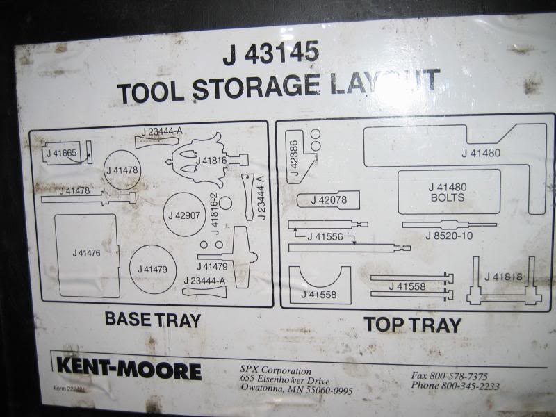
Wait until you price that lil gem LOL. These tools are obscenely exspensive lucky for me I have a friend that works for a GM dealership. Here is a pic of the inside of the cover on the case. It lists all the tools in the kit.
These motors have special tools for everything it's unreal. I am surprised there is no airfilter alignment tool LOL.
These motors have special tools for everything it's unreal. I am surprised there is no airfilter alignment tool LOL.

Wow lol. I just dapped black rtv in the corner where in me the oil pan/block. I centered using the crank pullley method as mentioned but not all the way installed. That's neat they have tools though.


I am getting ready to do a head/cam swap.
So, I bought a KENT MOORE J-43145 GEN III V8 ENGINE TOOL KIT to make the job go easier and not have issues.
So, I bought a KENT MOORE J-43145 GEN III V8 ENGINE TOOL KIT to make the job go easier and not have issues.
Thread Starter
9 Second Club
iTrader: (23)
Joined: Oct 2002
Posts: 1,150
Likes: 1
From: Mastic Long Island N.Y.

If you stop and think about it, once all the front cover bolts are in finger tight and the pulley is all the way home there isn't much side to side(horizontal) movement left. There really isn't any vertical movement available either since the lower face of the cover is sitting on upper front face of the oil pan and the oil seal on the front cover is also holding the front cover fast because the pulley hub is resident inside of the seal. We must be talking thousandths of an inch in available adjustment which the expensive KentMoore tools is going to correct for. I believe it's not only over priced, but overkill as well.
Last edited by eallanboggs; Jan 5, 2009 at 10:32 PM.
So is it necesary to use the alignment tools only when you remove the oil pan and the front/rear covers? If you only remove on of the 3, you should be able to use the other two as an alignment aid.
So, I cashed in my 401K plan and I bought a KENT MOORE J-43145 GEN III V8 ENGINE TOOL KIT to make the job go easier and not have issues.
Found the kit on Ebay. It was from a Chevy dealership that shut down.
If you're just removing and reinstalling the front cover without dropping the pan I don't see why you need the expensive Kent/Moore tool. If you're doing a rebuild it might be different. If the pan is flush to the block the front and rear covers can only be moved side to side a tiny amount with all the fasteners in the pulley in place. The pan can't move fore and aft because of the front and rear covers. It can only move side to side and very litte at that once the bolts are installed. I'd like to see two engine put together side by side one using the tool and one not. Then you could compare them to see how much of a difference there really is.
Joined: Nov 2001
Posts: 3,043
Likes: 0
From: Texas and Qatar
I first used these tools about 10 years ago. I don't use them much anymore but for the guys doing these in their garage the timing cover can be centered with a caliper or specific sized "dowels" if available. Assuming the oil pan is in place and the front crank seal is removed; the timing cover is centered when there is .680" gap around the perimeter of the crank snout to the seal housing bore. FWIW the red Snap-on 1/2" nut drivers are the correct OD .680" size also... I've often wanted to have a tapered sleeve that centers the timing cover made to make that easier.
The newer reverse lip rear main seals center the rear covers quite well without the tools, as long as the pan is installed first as posted above. I should note that if using that brass centering tool on the rear cover; the rear main seal needs to be removed, kind of a PITA if you bought a new cover with the seal already installed as you'll likely need another rear main seal.
The newer reverse lip rear main seals center the rear covers quite well without the tools, as long as the pan is installed first as posted above. I should note that if using that brass centering tool on the rear cover; the rear main seal needs to be removed, kind of a PITA if you bought a new cover with the seal already installed as you'll likely need another rear main seal.