


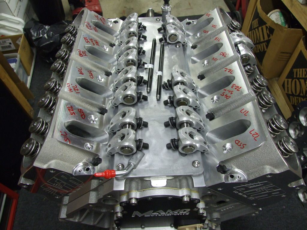


Darth Vader....Your LSx Stroker is ready!!
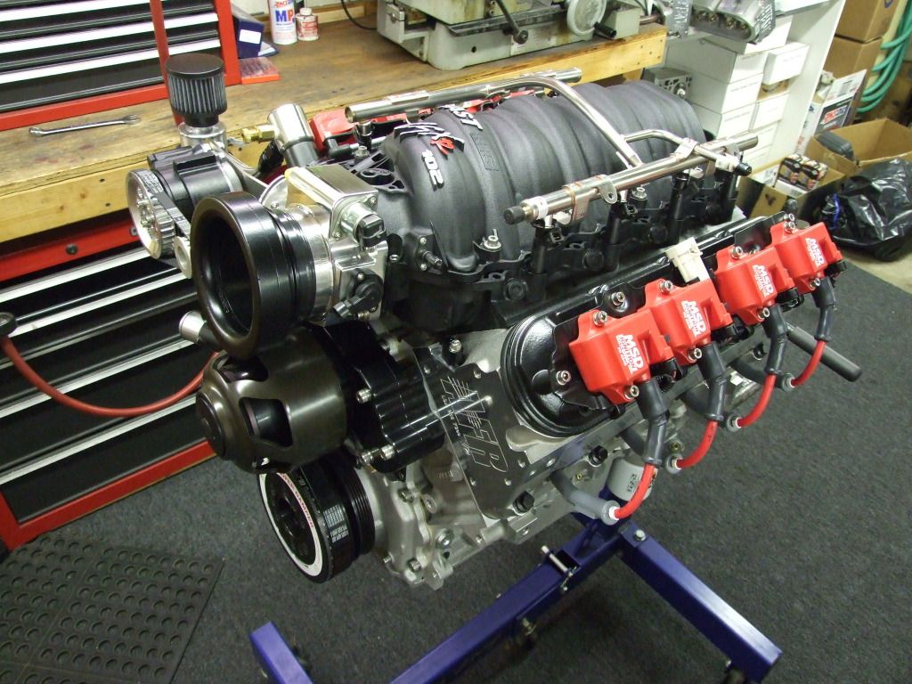
The next is how she sits as of an hour ago.....I forgot how damn sexy this engine was/is. Its great to see it back in one piece again!
yep, this is now my cpu's background screen!! Super nice work. Nice story as well. Hell it woke me up this morning. Thanks!
Keep up the hard, but good work!!!
yep, this is now my cpu's background screen!! Super nice work. Nice story as well. Hell it woke me up this morning. Thanks!
Keep up the hard, but good work!!!
Thanks for the update. It's an interesting read. What epoxy is used? Any concern of it losing adhesion?
Thought you had ditched the MSD coil packs, no?
Thought you had ditched the MSD coil packs, no?
Last edited by LS1-450; May 24, 2012 at 11:02 AM. Reason: corrected spelling

TECH Junkie
Joined: Dec 2005
Posts: 3,092
Likes: 11
I say let's see what happens on the Darth Vader motor before jumping to any conclusions. I find it interesting it gained down low but nothing on top which I think is a big clue. I have a couple of thoughts but will wait for the next dyno results.
Go Tony! Any idea when you think you'll get it back in the cell?
PS - that picture is giving me nightmares, and I'm wide awake! LOL

Staging Lane
Joined: Jan 2012
Posts: 84
Likes: 0
From: CHristchurch New Zealand
nice update! Tony, that engine is absolute art work, and you are an artist (not one of the gay looking ones in a funny hat mind you) absolutely love reading your posts with all the info you put into them and especially the progress on this project mate, keep up the amazing work 
Of course applying epoxy anywhere in an engine is never risk free but I roughed up the plastic pretty well so it had some "tooth" before applying the epoxy and quite honestly, even in the event a piece broke loose, this engine would probably ingest it and not even skip a beat! (If I have a problem it will be an excuse for Vader V3!). If you cruise some of the industry trade shows and walk through some of the cylinder head booths you may have noticed an "army green" color epoxy used on some of the prototype heads on display. That's the stuff I'm referring.....its a black and yellow two part epoxy that turns army green in color when mixed properly just prior to its application.
Regarding the MSD's the look is worth the price of admission for me and I had no issues with spark drop or some of the little nuances that plagued them in the past. I think they may have improved the design of the coils or at least thats what I was told. Is it the first place I would drop $500 looking for a performance increase.....certainly not, but for me having covered every other base already, the thought of a slightly hotter spark with more dwell time and ultimately the "look" sitting on this engine sealed the deal.
Regarding the wipe pattern, you are correct that changing the stand height will slightly effect the wipe pattern but the reality is stand height change of +/- .010 will have very negligible effects. Also, what made this even more challenging is I had to plan ahead for the rocker swap I am making during the testing. I will initially be running a 1.8/1.7 combination and I will see if a 1.8 rocker on the exhaust helps power some which I suspect it might so I had to check the pushrod/lifter preload for two exhaust set-ups (a 1.7 ratio and a 1.8 ratio). Changing the rocker bodies and the ratio did have an effect on lifter preload/pushrod length so it was even more challenging mainly because I was being so **** on wanting to keep the preload exact which really isn't necessary (but I could have said the same of lots of painstaking details I invested the time to make it the best I could.....just goes with the territory and the nature of this build). It would have been alot easier of course if I had two dozen more varied length pushrods to pull from but I ordered 26 of them thinking I would be covered and essentially worked around the lengths that they sent me (which often vary a few thou from what you order). When the smoke cleared, to work with what I had required a slight increase in shim/stand height to juggle and make everything work if I was looking to achieve lifter preload perfection.....LOL.
You mention gaining on the bottom and nothing up top offering you a clue.....I'm up for hearing those thoughts now before I hit the dyno.....LOL
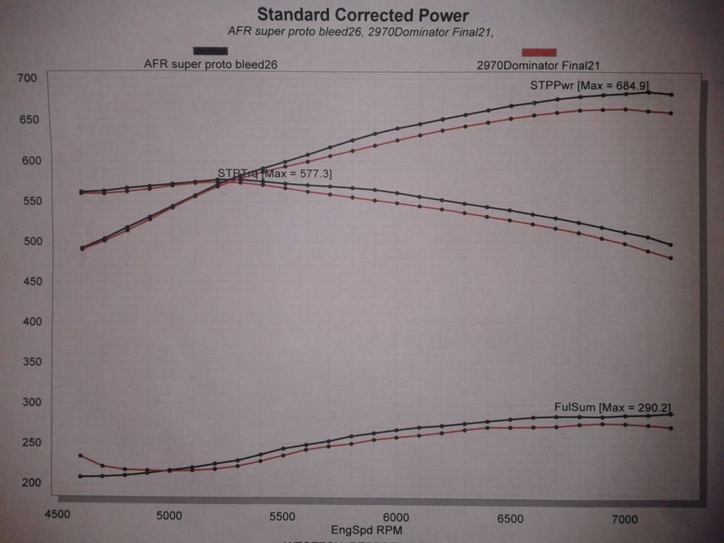
Keep in mind and just to reiterate, I did not change the runner lengths which could (and should) effect the area of the curve the manifold becomes more effective. I simply improved the efficiency of the runner lengths already inherent in that design. Im all ears on what you might be thinking because usually when you install a better flowing manifold that results are just the opposite.....the higher the RPM, the better the gains from the manifold typically look (assuming similar design, runner lengths, etc.).
For example the two curves below represent the same intake.....the better looking curve that made more power is the same intake after I had ported it. Note the large gains are all upstairs when the air demand on the intake tract is the highest and the motor has sooooo little time for the valves to to fill (or evacuate) the cylinder. This wasn't an LS engine btw, but the same principles apply IMO
Guys.....thanks for all the support, positive comments etc. Im really looking forward to the next round of testing. At the very least it promises to be exciting and answer some questions.
Im trying to schedule dyno time in the next week or so.....as soon as I have some results I will obviously fill you guys in.
I still have another story to tell on the next "saga" related to this build which is my vision of a new head I designed for Vader V2 (the current configuration I'm about to test). Im referring of course to a new 255 cc port which is essentially a variant of the AFR 245 program that has an even larger intake valve (2.200 versus 2.165) and a smaller exhaust (1.570) that was needed to accommodate and make room for the larger intake. Of course like the 245 head I ran last time I included alot of additional time after the CNC romancing and tweaking the ports some by hand (I posted some photos of this head in post #189).
The new 255 prototype is the best flowing cathedral head I have ever tested to date at 385-390 CFM (those are respectable ported LS7 head figures), but there is more to the story. I will discuss more of the good (and some things not so good) of that mad hatter project with you guys very soon when I have a some additional time to type but the bottom line is I hope this new head design helps propel the V2 version of Vader to new highs and closer to the 750 goal I am looking to achieve.
Cheers,
Tony
Last edited by Tony Mamo @ AFR; May 23, 2012 at 02:32 PM.
TECH Junkie
Joined: Dec 2005
Posts: 3,092
Likes: 11
"but for whatever reason that 408 simply didn't care about it."
Exactly. The 408 was not using all the available air from the new intake in the upper rpms. It sure liked the "new found" air in the lower rpms. You would have to start looking at things like the camshaft/valve train, exhaust etc. Something was holding it back in the upper rpms and not allowing it to breath like it could as it was hitting a brick wall so to speak. As everyone says let's just move on to the Vader motor and see what happens there. That will help tell the tail on the intake manifold.
Exactly. The 408 was not using all the available air from the new intake in the upper rpms. It sure liked the "new found" air in the lower rpms. You would have to start looking at things like the camshaft/valve train, exhaust etc. Something was holding it back in the upper rpms and not allowing it to breath like it could as it was hitting a brick wall so to speak. As everyone says let's just move on to the Vader motor and see what happens there. That will help tell the tail on the intake manifold.
Tony, thanks for the reply regarding the epoxy. I've had an extensively ported & filled LS2 intake for 4-5 yrs now that was bought on Tech. Never could find out what epoxy to use in order to finish it up...until now.
Just have to figure out how to keep the floor of the intake from coming loose, now. It had been removed for the interior plenum fill. This epoxy may be the answer for it ,as well. We will see.
Looking forward to your next dyno session results.
Just have to figure out how to keep the floor of the intake from coming loose, now. It had been removed for the interior plenum fill. This epoxy may be the answer for it ,as well. We will see.
Looking forward to your next dyno session results.
LS1 Tech Stories
The Best V8 Stories One Small Block at Time

Gas Monkey Built a 6-Wheel Ferrari Testarossa With a Corvette LT4 Engine
Verdad Gallardo
7 Most Reliable High-Performance Engines GM Has Ever Built
Verdad Gallardo
Amazing '71 Camaro Restomod Is Modern Muscle Car Under the Skin
Verdad Gallardo
6 Common C5 Corvette Failures and What's Involved In Repairing Them
Pouria Savadkouei
Retro Modern Bandit Pontiac Trans AM Comes With Burt Reynolds' Autograph
Verdad Gallardo
Top 10 Greatest Cadillac V Series Performance Models Ever, Ranked
Pouria Savadkouei
Top 10 Most Powerful Chevy Trucks Ever Made!

Hennessey's New Supercharged Silverado ZR2 Has 700 HP
Verdad Gallardo
Coachbuilt N2A Anteros Is an LS2-Powered C6 Corvette In Italian Clothes
Verdad Gallardo Tony, I think youll reach your goal, and then some! 390cfm out of a cathedral head is definitely nothing to complain about!
A question for ya. I know when your optimizing an engine, you want to match the cam specs to the heads and intake type (single plane compared to FAST for example) but what about the intake flow? With you changing the flow characteristics of the manifold, could a cam change be beneficial, or is it not as sensitive to flow changes in that area?
A question for ya. I know when your optimizing an engine, you want to match the cam specs to the heads and intake type (single plane compared to FAST for example) but what about the intake flow? With you changing the flow characteristics of the manifold, could a cam change be beneficial, or is it not as sensitive to flow changes in that area?

Guys,
Where do I begin....a ways back I lost a couple of days on the dyno due to a bad computer/ignition box.....we spent hours trying to track down/trouble shoot the problem. Westech ended up replacing the box at a later date which cured the issues we were having. Weeks later I dislocated my shoulder (badly) days before my next scheduled dyno date....that is only just getting better now and it takes months before its really back.
Anyway, there's actually more (a few other curve ***** related to this project) but I wont bother getting into it.....some of it good though....LOL
The "good" is I recently purchased a 2009 CTS-V which will become my next project car. Bad azz ride and any of you considering one shouldn't take one for a test drive or it will haunt you till you own one! Really impressive car....
Anyway, I have also decided I wanted to test something else and since the entire Vader build has gone completely off the deep end related to time I'm not rushing any more and stressing over its completion date. I have too much going on right now playing catch up a bit from the injury and the down time getting this CTS-V purchase sorted out (not to mention I can play around in the "V" now to hold me over....LOL).
I hope to be back on the dyno in a month or so realistically....could even be longer but I hope not. If I won the lotto tomorrow I probably have enough projects in the works that I would still be busy till I couldn't pick up a skill saw or a torque wrench any longer! (and those who really know me and read this are laughing knowing its true!).
Sorry for the delay guys.....I know its disappointing.
Regarding the timing cover you can get the exact same one without my logo from Edelbrock....Its a cool piece and functional for moving the cam around on the dyno. A few people have asked me about the logo version.....the next time I have the opportunity to run one again I may run a few of them in the event a few of you want to buy one. The program is still in the CNC machine....just need the set-up time and the pieces to make it happen.
I promise there will be an end to this saga soon....and chassis dyno results, track results, and videos to follow after that but knowing my schedule that will likely be another six months down the road! It will be worth the wait though....this engine is going to be an absolute blast in my 3250 lb Vette....the torque curve will be almost impossible to tame if the speedo is registering two digits!

Cheers guys
-Tony
Where do I begin....a ways back I lost a couple of days on the dyno due to a bad computer/ignition box.....we spent hours trying to track down/trouble shoot the problem. Westech ended up replacing the box at a later date which cured the issues we were having. Weeks later I dislocated my shoulder (badly) days before my next scheduled dyno date....that is only just getting better now and it takes months before its really back.
Anyway, there's actually more (a few other curve ***** related to this project) but I wont bother getting into it.....some of it good though....LOL
The "good" is I recently purchased a 2009 CTS-V which will become my next project car. Bad azz ride and any of you considering one shouldn't take one for a test drive or it will haunt you till you own one! Really impressive car....
Anyway, I have also decided I wanted to test something else and since the entire Vader build has gone completely off the deep end related to time I'm not rushing any more and stressing over its completion date. I have too much going on right now playing catch up a bit from the injury and the down time getting this CTS-V purchase sorted out (not to mention I can play around in the "V" now to hold me over....LOL).
I hope to be back on the dyno in a month or so realistically....could even be longer but I hope not. If I won the lotto tomorrow I probably have enough projects in the works that I would still be busy till I couldn't pick up a skill saw or a torque wrench any longer! (and those who really know me and read this are laughing knowing its true!).
Sorry for the delay guys.....I know its disappointing.
Regarding the timing cover you can get the exact same one without my logo from Edelbrock....Its a cool piece and functional for moving the cam around on the dyno. A few people have asked me about the logo version.....the next time I have the opportunity to run one again I may run a few of them in the event a few of you want to buy one. The program is still in the CNC machine....just need the set-up time and the pieces to make it happen.
I promise there will be an end to this saga soon....and chassis dyno results, track results, and videos to follow after that but knowing my schedule that will likely be another six months down the road! It will be worth the wait though....this engine is going to be an absolute blast in my 3250 lb Vette....the torque curve will be almost impossible to tame if the speedo is registering two digits!
Cheers guys
-Tony
Yah, I hope this doesn't mean step tuning in order to reduce under the curve torque. If it's got it, would be a shame not to use all of it.

No major plans initially....a really killer detail making a 3 year old car look new which is already under way. Some custom aesthetic touches on the body, Forgeline DS3 rims and Pilot Super Sport tires. I will be upgrading to Hawk HPS pads and detailing the brakes and rotors (I'm literally going to cross drill and slot the OEM rotors for a more aggressive look....going to work with Engineering to write a program for the CNC hopefully). Then just drive the hell out of it till I decide what to do about heads, cam, etc but this car will always drive as good as stock or better....any performance upgrades will never come at the expense of one ounce of drivability....that's what will make modding this car more interesting and it will be fun to see what I can get out of it while having it act as docile as stock. I will be porting the stock blower case as well when I get into the engine a bit.....maybe even sooner....LOL
For now though, all the wheel/tire and body/interior aesthetic mods.....it already has plenty of punch with a CAI and a pulley swap (580 ish RWHP per previous owners dyno graph). I will post some pics when Im done with the transformation.
The car is going to be a major handful to drive....semi dangerous in fact but that's what gets the heart rate going and thats what will make this car an E-ticket ride every time I decide to step foot in it. My 83' was alot to handle (very explosive) and the comparison of the two power curves is almost comical so I really will have to learn some restraint with the big engine but believe me I'm not going to tune any of the torque out of it....just need to try and learn how to harness it best I can without putting the car sideways into the next lane!
Cheers,
Tony
FormerVendor
Joined: Nov 2001
Posts: 3,065
Likes: 6
From: Houston, Tx.
Get well Tony and I feel your pain! I dislocated my left arm so bad about 10 years ago that I needed surgery which I did not get. After about 3 weeks it quit trying to come out and I slept on it to keep it popped in on an air mattress still expecting to get surgery but waiting for my insurance to be able to pay part, Well 10 years later it is fine but it really sucked and took about 3 months to feel "normal" again.
I think I need a CTS-V as well in my near future they are awesome cars.
I think I need a CTS-V as well in my near future they are awesome cars.
On The Tree
Joined: Dec 2004
Posts: 124
Likes: 0
From: Northville, Michigan
Guys,
Regarding the timing cover you can get the exact same one without my logo from Edelbrock....Its a cool piece and functional for moving the cam around on the dyno. A few people have asked me about the logo version.....the next time I have the opportunity to run one again I may run a few of them in the event a few of you want to buy one. The program is still in the CNC machine....just need the set-up time and the pieces to make it happen.
Cheers guys
-Tony
Tony,
Any leak issues with the two-piece cover. How do you seal the two halves?
JR
No issues sealing whatsoever with the two piece cover.
There is a small O-ring that goes around the perimeter of the base (a solid one piece O-ring) that the flat machined cover (the part I machined my logo in) seals against to eliminate oil leaks.
The only "fail" in the design is the O-ring groove is too wide and doesnt capture or positively hold the Oring and it goeas around the perimeter in a very convoluted shape. If the groove was smaller it could have grabbed and held the Oring in place for ease of install and future removal and install as well.
I ended up siliconing it into the groove in various spots lightly taping it in place till the silicone set up. Then I removed the tape carefully and the O-ring was held in place now and for future removals as well.
I'm dumbfounded why Edelbrock just didn't machine a smaller groove (its not even close to the right size if we are discussing capturing the O-ring properly), but truthfully they did alot of things right with this two piece design cover so its still a worthwhile item to purchase, especially if you want to play around with your cam installed position on the dyno.
Cheers,
Tony
PS....It wont leak at all assuming you handle/locate the O-ring situation properly