


My 347ci build
I like this thread, good info here.
My shortblock is at the shop and I'm gonna make sure that its decked and all the pistons come out of the hole evenly!
Should I ask them to take before measurements of Piston out of the hole before decking? That way they know how much to take off equally
They are a good shop, but I have OCD
My shortblock is at the shop and I'm gonna make sure that its decked and all the pistons come out of the hole evenly!
Should I ask them to take before measurements of Piston out of the hole before decking? That way they know how much to take off equally
They are a good shop, but I have OCD
Thanks man, lots of great info in your build thread as well! I see you're running AFR's with the comp upgraded stock rockers. Any issues doing this that you've encountered? I was thinking about getting some 205's, and wasn't sure if that meant I needed to upgrade to roller rockers (something that wouldn't side load and prematurely wear the bronze valve guides they use). Right now I've got the comp upgraded rockers with a cam that's .61x/.58x lift.
Thank you sir, it has worked really well so far. The o-rings do a really good job of preventing any marring of the bearing surface when installing. When you're making it, size the flange on the driver head for the #3 bearing bore, it's the smallest one. If I had to change anything, I would have put a longer handle on it so I could do everything from the same side. At present I have to take the block off the stand to get to #4 and #5, but isn't a big deal - just kind of a pita. I think I have the dimensions for the driver head around here somewhere, if I can find them I'll post them up. Might save you some work.
Thank you sir, it has worked really well so far. The o-rings do a really good job of preventing any marring of the bearing surface when installing. When you're making it, size the flange on the driver head for the #3 bearing bore, it's the smallest one. If I had to change anything, I would have put a longer handle on it so I could do everything from the same side. At present I have to take the block off the stand to get to #4 and #5, but isn't a big deal - just kind of a pita. I think I have the dimensions for the driver head around here somewhere, if I can find them I'll post them up. Might save you some work.
Last edited by ckpitt55; Mar 2, 2013 at 02:19 PM.
LS1 Tech Stories
The Best V8 Stories One Small Block at Time

6 Common C5 Corvette Failures and What's Involved In Repairing Them
Pouria Savadkouei
Retro Modern Bandit Pontiac Trans AM Comes With Burt Reynolds' Autograph
Verdad Gallardo
Top 10 Greatest Cadillac V Series Performance Models Ever, Ranked
Pouria Savadkouei
Top 10 Most Powerful Chevy Trucks Ever Made!

Hennessey's New Supercharged Silverado ZR2 Has 700 HP
Verdad Gallardo
Coachbuilt N2A Anteros Is an LS2-Powered C6 Corvette In Italian Clothes
Verdad Gallardo
Awesome K5 Blazer Restomod Comes With C7 Corvette Power
Verdad Gallardo
10 Camaros You Should Never Buy

10 LS Engine Myths That Refuse to Die
Verdad GallardoTECH Fanatic

Joined: Jun 2011
Posts: 1,343
Likes: 8
From: Katy, TX
Thanks man, lots of great info in your build thread as well! I see you're running AFR's with the comp upgraded stock rockers. Any issues doing this that you've encountered? I was thinking about getting some 205's, and wasn't sure if that meant I needed to upgrade to roller rockers (something that wouldn't side load and prematurely wear the bronze valve guides they use). Right now I've got the comp upgraded rockers with a cam that's .61x/.58x lift.
I've also seen threads where experienced engine builders have used the combination (bronze guides and stock rockers) for years with no issues. And the ones that have had issues are sketchy on the details, with no real assurance of the root cause.
Basically, the evidence I've seen is FAR from conclusive.
I've got a customer that will be using stock rockers with afr heads here soon so I'll keep the thread updated on longevity of the guides.
That said two of the most experienced builders I know that I highly respect(tooley and mike@tea) both have told me it is just a matter of time from the side loading a stock non roller tipped rocker incurs on the valve guide. I'll keep everyone updated with results because I want to see myself.
That said two of the most experienced builders I know that I highly respect(tooley and mike@tea) both have told me it is just a matter of time from the side loading a stock non roller tipped rocker incurs on the valve guide. I'll keep everyone updated with results because I want to see myself.
yeah, I debated that for a long time. In the end I kept the stock rockers because I had several reliable sources tell me that it was ok for my relatively low valve lift (0.566/0.571). No issues yet, but I've only got about 4k on the new motor.
I've also seen threads where experienced engine builders have used the combination (bronze guides and stock rockers) for years with no issues. And the ones that have had issues are sketchy on the details, with no real assurance of the root cause.
Basically, the evidence I've seen is FAR from conclusive.
That said two of the most experienced builders I know that I highly respect(tooley and mike@tea) both have told me it is just a matter of time from the side loading a stock non roller tipped rocker incurs on the valve guide. I'll keep everyone updated with results because I want to see myself.
Originally Posted by Tony
Stock rockers will always wear the guides alot faster....go to Yella Terras if you want to avoid this.
The roller rockers (theoretically) have only one point of contact on the valve at all times, allowing it to only provide a force normal to the valve motion which prevents side wear. That friction component of force that is conventionally used to keep the two surfaces in contact is converted into rotational motion of the roller to keep it better centered over the valve.
I don't know if any of that makes sense, but that's how I'm thinking about it. One more thing to do more research on lol
edit: I like pictures


"A stock GM rocker opens the valve just like a rocking chair, moving from the intake side of the head to the exhaust side, without any real movement between the two, working like two gears meshing together if that makes sense, or just like how a rocking chair "rocks" on the floor. From .550" lift on it actually pulls the rocker arm backwards across the valve tip scrubbing the end of the rocker arm into the valve tip, this is where valve tip and valve guide wear stem from. I have seen the stock rocker drawn in CAD that could be put in motion and it works beautiful until .550" lift, from there on it looks scary."
Looks as though the roller better distributes the side loading above .550" lift, not necessarily that it prevents it
Last edited by ckpitt55; Mar 3, 2013 at 02:57 PM.
TECH Fanatic
Joined: Jun 2011
Posts: 1,343
Likes: 8
From: Katy, TX
I've got a customer that will be using stock rockers with afr heads here soon so I'll keep the thread updated on longevity of the guides.
That said two of the most experienced builders I know that I highly respect(tooley and mike@tea) both have told me it is just a matter of time from the side loading a stock non roller tipped rocker incurs on the valve guide. I'll keep everyone updated with results because I want to see myself.
That said two of the most experienced builders I know that I highly respect(tooley and mike@tea) both have told me it is just a matter of time from the side loading a stock non roller tipped rocker incurs on the valve guide. I'll keep everyone updated with results because I want to see myself.
What kind of issues or warning signs could you expect from worn guides short of dropping valves? Noise, oil consumption? I guess the problem here is that if your clearances become excessive, the valve bends further before it's supported by the guide wall? More bending = more fatigue, more fatigue = more likelihood of failure.
- checking the oil cap for blow-by
- regular oil analysis to check for combustion byproducts and/or excessive levels of tin (1st analysis at 2.5k miles came back clean)
- visual inspection of the top of the valve guide with spring and seal removed (after maybe 8-10k miles)
I think it makes sense, the stock rockers can't roll to self-align with the valve tip through travel, so you always will have some force component side loading the guide. The side loading is a bending force, and it can only exist if the rocker arms line of action isn't parallel AND aligned with the vertical axis of the valve stem. So if that contact point is somewhere off-center, you get side loading. The part of the rocker pressing on the valve in this case is only perpendicular and centered to the valve for a very short time frame. It also makes sense that going to bigger lifts increases wear because it increases the amount of time you spend away from this perfect "contact center" that occurs somewhere mid-lift. Areas above and below that center point in mid travel see the side loading component increase as the contact angles become more exaggerated.
I'm taking the block to the shop tomorrow to have them inspect / line hone the main bores, but figured I'd check my crank endplay while I still have it in the block. I don't expect it to change but will be checking it again once I go to final assembly, just wanted to get a ball park estimate.
Gauge zeroed on crank snout, mounted to the block with a fixture I made. Couple pieces of scrap aluminum, couple of drilled and tapped holes, and a couple of set screws. Pretty simple to make - save yourself $70+ and make it yourself. Crank thrust bearing was referenced using a dead blow hammer, knocking it forward and then back. Spins freely by hand.


Approx 0.0035" endplay, repeatable to within a tenth. Well within the 0.0015 - 0.0078" spec.

Last edited by ckpitt55; Mar 3, 2013 at 04:31 PM.
What kind of issues or warning signs could you expect from worn guides short of dropping valves? Noise, oil consumption? I guess the problem here is that if your clearances become excessive, the valve bends further before it's supported by the guide wall? More bending = more fatigue, more fatigue = more likelihood of failure.
I Pm'd Tony Mamo about this also, what he said seems to align with what Brian and Mike had to say.
I think it makes sense, the stock rockers can't roll to self-align with the valve tip through travel, so you always will have some force component side loading the guide. The side loading is a bending force, and it can only exist if the rocker arms line of action isn't parallel AND aligned with the vertical axis of the valve stem. So if that contact point is somewhere off-center, you get side loading. The part of the rocker pressing on the valve in this case is only perpendicular and centered to the valve for a very short time frame. It also makes sense that going to bigger lifts increases wear because it increases the amount of time you spend away from this perfect "contact center" that occurs somewhere mid-lift. Areas above and below that center point in mid travel see the side loading component increase as the contact angles become more exaggerated.
The roller rockers (theoretically) have only one point of contact on the valve at all times, allowing it to only provide a force normal to the valve motion which prevents side wear. That friction component of force that is conventionally used to keep the two surfaces in contact is converted into rotational motion of the roller to keep it better centered over the valve.
I don't know if any of that makes sense, but that's how I'm thinking about it. One more thing to do more research on lol
edit: I like pictures
"A stock GM rocker opens the valve just like a rocking chair, moving from the intake side of the head to the exhaust side, without any real movement between the two, working like two gears meshing together if that makes sense, or just like how a rocking chair "rocks" on the floor. From .550" lift on it actually pulls the rocker arm backwards across the valve tip scrubbing the end of the rocker arm into the valve tip, this is where valve tip and valve guide wear stem from. I have seen the stock rocker drawn in CAD that could be put in motion and it works beautiful until .550" lift, from there on it looks scary."
Looks as though the roller better distributes the side loading above .550" lift, not necessarily that it prevents it

Took the block to another shop after work today to have them look at the mains. Speaking with the owner, they seem to be a lot more confident working on the aluminum LS blocks than the other place was. They'll also be checking out the cylinder bores, I noticed a bit of taper and out of round when doing my measurements. Wasn't a lot, but wasn't nothing either. Unfortunately I don't have much of an intuition yet on what kind of post machining tolerances are healthy or not. So we'll see what they say, hopefully I get it back relatively soon so I can complete the shortblock. In the mean time, I'll measure my rod bores for proper size and measure my rod bearing clearances. Also starting to put together my plans for the rest of the motor. Somehow in the past week or two it's evolved from a mild build to a no-holds-barred build. Funny how sometimes a project takes on a life of its own lol. More to come very soon, hopefully.
Also figured I'd take a few minutes tonight to post up the dimensions and materials I used to make my cam bearing tool. I would make them but I don't have the means to do so without bugging my friend to let me borrow some time on his lathe. I might be able to make a few in small quantities though if there's enough interest.
raw materials sourced from mcmaster carr (http://www.mcmaster.com):
PN# 9941K31, 2-1/2" hardwood ball
PN# 1610T61, 2-1/2" x 3" lg 6061 Aluminum Rod, temper T6511
PN# 8920K252, 1-1/8" dia x 1' lg low-carbon steel rod
For the o-rings - I ended up using size #131. Took me some trial and error to get the right combination of stretch/compression on the driver head. The 131's were as close as I could get to the perfect amount of interference with the bearing to retain it / protect it, yet allow it to easily slip off as well.
If I were to do it all over again I would have used the 3' handle to allow you to install all bearings from the same direction. I would also suggest that you only hit the end of the handle with a brass hammer. Dead blows would probably also work but you lose that distinct "snappy" impact that is useful when creating or overcoming press fits. I used a steel hammer, and through use the end of the handle mushroomed, preventing the wooden ball from being able to slide off in that direction. Not a dealbreaker but just something I observed.
Cam bearing bore sizes for reference:
1 and 5: 2.3260/2.3280
2 and 4: 2.3161/2.3181
3: 2.3063/2.3083
**As you can see, the #3 bore dictates the size of the driver flange
Cam Bearing OD and ID's (Clevite)
1/5 -- OD: 2.334/2.336 ID: 2.168/2.166
2/4 -- OD: 2.326/2.322 ID: 2.164/2.164
3 -- OD: 2.317 ID: 2.165
I made this drawing in autocad.

Some notes:
*drill a thru hole in the driver for a bolt of your choosing, I counterbored mine to recess the head of the bolt.
*face the mating surfaces of the head and driver so they sit flush when bolted down. drill and tap the handle for whatever bolt you're using
*measure the handle and drill the wooden ball to match, starting with a smaller bit. creep up on the desired size until it's a tight fit. you don't want it to be able to wiggle at all because this is what "self-aligns" to be parallel with the axis of the bore. This makes lining up the driver to the bearing stupid easy on installation as well as removal.
*chamfer / debur all edges that could either contact a bearing, a bearing bore in the block, or an o-ring. you don't want to damage any of these.
*the spacing of the two o-ring grooves isn't all that critical, but keep them both within about 5/8" of an inch from the bearing contact surface of the driver as the bearing is only about 0.630" wide.
*coat the driver head (and o-rings) with oil prior to throwing on the bearing, protects the bearing from being chaffed
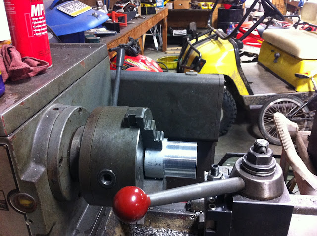
Here's a few pics from when I made mine:
OD turned
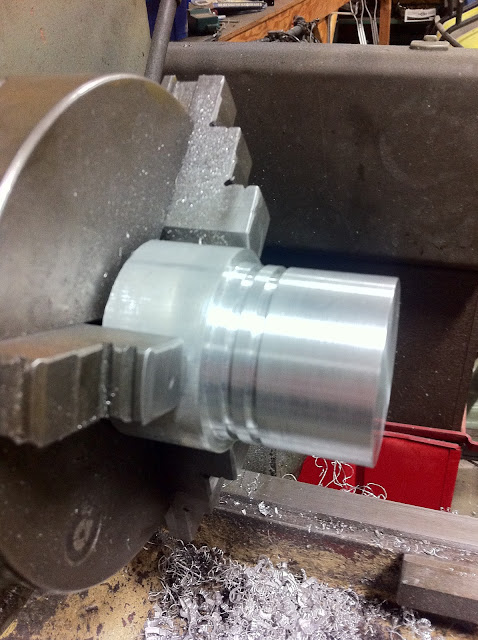
O-ring grooves cut
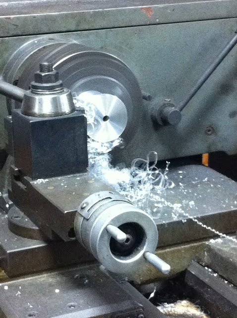
Mating surface of the driver faced
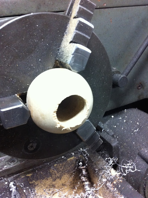
Wooden ball drilled with a spade bit then bored to size
finished tool minus o-rings. doesn't look quite as nice now, but i guess thats to be expected from something you hammer the **** out of on occasion
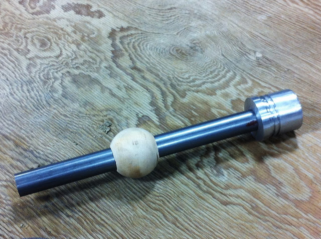
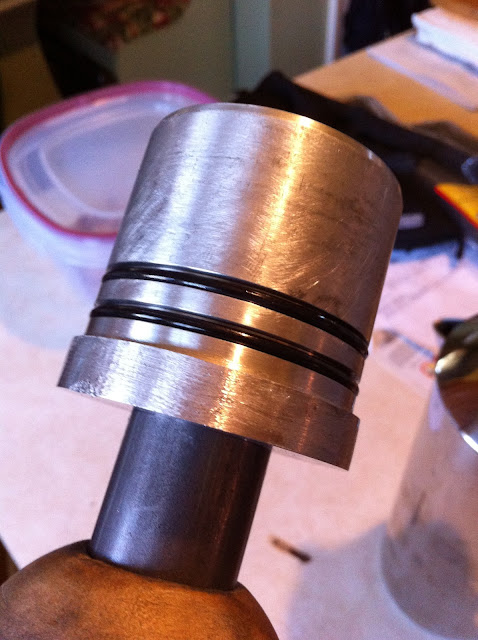
closeup of the driver head with o-rings installed. take note of the chamfers.
If anyone has any other questions on machining this or using it, feel free to message me.
raw materials sourced from mcmaster carr (http://www.mcmaster.com):
PN# 9941K31, 2-1/2" hardwood ball
PN# 1610T61, 2-1/2" x 3" lg 6061 Aluminum Rod, temper T6511
PN# 8920K252, 1-1/8" dia x 1' lg low-carbon steel rod
For the o-rings - I ended up using size #131. Took me some trial and error to get the right combination of stretch/compression on the driver head. The 131's were as close as I could get to the perfect amount of interference with the bearing to retain it / protect it, yet allow it to easily slip off as well.
If I were to do it all over again I would have used the 3' handle to allow you to install all bearings from the same direction. I would also suggest that you only hit the end of the handle with a brass hammer. Dead blows would probably also work but you lose that distinct "snappy" impact that is useful when creating or overcoming press fits. I used a steel hammer, and through use the end of the handle mushroomed, preventing the wooden ball from being able to slide off in that direction. Not a dealbreaker but just something I observed.
Cam bearing bore sizes for reference:
1 and 5: 2.3260/2.3280
2 and 4: 2.3161/2.3181
3: 2.3063/2.3083
**As you can see, the #3 bore dictates the size of the driver flange
Cam Bearing OD and ID's (Clevite)
1/5 -- OD: 2.334/2.336 ID: 2.168/2.166
2/4 -- OD: 2.326/2.322 ID: 2.164/2.164
3 -- OD: 2.317 ID: 2.165
I made this drawing in autocad.
Some notes:
*drill a thru hole in the driver for a bolt of your choosing, I counterbored mine to recess the head of the bolt.
*face the mating surfaces of the head and driver so they sit flush when bolted down. drill and tap the handle for whatever bolt you're using
*measure the handle and drill the wooden ball to match, starting with a smaller bit. creep up on the desired size until it's a tight fit. you don't want it to be able to wiggle at all because this is what "self-aligns" to be parallel with the axis of the bore. This makes lining up the driver to the bearing stupid easy on installation as well as removal.
*chamfer / debur all edges that could either contact a bearing, a bearing bore in the block, or an o-ring. you don't want to damage any of these.
*the spacing of the two o-ring grooves isn't all that critical, but keep them both within about 5/8" of an inch from the bearing contact surface of the driver as the bearing is only about 0.630" wide.
*coat the driver head (and o-rings) with oil prior to throwing on the bearing, protects the bearing from being chaffed
Here's a few pics from when I made mine:
OD turned
O-ring grooves cut
Mating surface of the driver faced
Wooden ball drilled with a spade bit then bored to size
finished tool minus o-rings. doesn't look quite as nice now, but i guess thats to be expected from something you hammer the **** out of on occasion
closeup of the driver head with o-rings installed. take note of the chamfers.
If anyone has any other questions on machining this or using it, feel free to message me.
Last edited by ckpitt55; Mar 7, 2013 at 06:51 AM.