

My 347ci build
 02-12-2013, 12:37 PM
#1
Figured I'd share my build with you guys since this place has been a wealth of knowledge for me.
I started with an LS1/T56 dropout from an '02 trans am w/ 38k miles for my swap project. I tore the engine down to inspect its condition and found several things wrong. 1) Too much taper and o-o-R in the bores, 2) piston to cylinder clearances too loose, 3) crankshaft casting defect on one of the main journals, 3) main, rod, and cam bearings were all shot.
The seller replaced the crank for free since the parts were still under warranty. I was on my own for everything else though. After a few months of research and playing with compression calculators, my build list ended up like this so far. Shooting for 11.5-ish:1 static, 8.5:1 dynamic, tight quench.
Build list (updated 5/21/13):
Shortblock
Stock LS1 crankshaft
Callies Compstar forged 6.125" h-beam rods
Diamond #11502 flat top pistons - 3.905" bore size w/ plasma-moly ring set
Clevite-H -0.001"/std main bearings, mixed and matched to modify clearances
Clevite-H -0.001"/std rod bearings, mixed and matched to modify clearances
Durabond high performance camshaft bearings
Cometic MLS 4.135" x 0.040" gaskets
TSP ported ls6 oil pump
Cloyes Hex-a-just single row adjustable timing set
Trick flow LS2 timing chain dampener
ATI crank pulley 10% ud
ARP head and main studs
Heads/Cam/Valvetrain
Mamofied AFR 215cc heads, 58.5cc chambers, lightweight 2.02" intake valves, 8019 springs
Tick Performance Street Heat Stage 2 cam (231/238, .61x/.58x, 113+3)
Trend dual tapered 3/8"-5/16"
Johnson limited travel linkbar lifters (solid axles with oiling)
Yella terra ultralite 1.7 roller rockers PN 6645 (Revision 3)
Intake/Fueling
Mamofied FAST 102 intake
FAST 102 throttle body
FAST 36lb injectors
OEM style FAST 102 fuel rail
TSP 100mm MAF w/ saxonpc honeycomb screen (supposedly improves flow and alleviates metering issues)
Misc Long block
Improved Racing f-body oil pan baffle
LS6 valley cover
Just got my block back from machining. Got a clean-up cut on the decks, torque plate hone for the new pistons, and the rotating assembly balanced.
Update: 4/29/13
Cylinder bores cut for roundness and opened up a bit, along with main bore line hone at a second shop. See Page 5


I opted to do all the assembly work myself. I have too much energy and money invested at this point to trust that process to someone else who may or may not care about getting it right as much as I do. Going to get this thing clean, then start blueprinting and pre-assembling. I'll keep this thread updated with my progress for any who may be interested. Thanks for looking.
I started with an LS1/T56 dropout from an '02 trans am w/ 38k miles for my swap project. I tore the engine down to inspect its condition and found several things wrong. 1) Too much taper and o-o-R in the bores, 2) piston to cylinder clearances too loose, 3) crankshaft casting defect on one of the main journals, 3) main, rod, and cam bearings were all shot.
The seller replaced the crank for free since the parts were still under warranty. I was on my own for everything else though. After a few months of research and playing with compression calculators, my build list ended up like this so far. Shooting for 11.5-ish:1 static, 8.5:1 dynamic, tight quench.
Build list (updated 5/21/13):
Shortblock
Stock LS1 crankshaft
Callies Compstar forged 6.125" h-beam rods
Diamond #11502 flat top pistons - 3.905" bore size w/ plasma-moly ring set
Clevite-H -0.001"/std main bearings, mixed and matched to modify clearances
Clevite-H -0.001"/std rod bearings, mixed and matched to modify clearances
Durabond high performance camshaft bearings
Cometic MLS 4.135" x 0.040" gaskets
TSP ported ls6 oil pump
Cloyes Hex-a-just single row adjustable timing set
Trick flow LS2 timing chain dampener
ATI crank pulley 10% ud
ARP head and main studs
Heads/Cam/Valvetrain
Mamofied AFR 215cc heads, 58.5cc chambers, lightweight 2.02" intake valves, 8019 springs
Tick Performance Street Heat Stage 2 cam (231/238, .61x/.58x, 113+3)
Trend dual tapered 3/8"-5/16"
Johnson limited travel linkbar lifters (solid axles with oiling)
Yella terra ultralite 1.7 roller rockers PN 6645 (Revision 3)
Intake/Fueling
Mamofied FAST 102 intake
FAST 102 throttle body
FAST 36lb injectors
OEM style FAST 102 fuel rail
TSP 100mm MAF w/ saxonpc honeycomb screen (supposedly improves flow and alleviates metering issues)
Misc Long block
Improved Racing f-body oil pan baffle
LS6 valley cover
Just got my block back from machining. Got a clean-up cut on the decks, torque plate hone for the new pistons, and the rotating assembly balanced.
Update: 4/29/13
Cylinder bores cut for roundness and opened up a bit, along with main bore line hone at a second shop. See Page 5
I opted to do all the assembly work myself. I have too much energy and money invested at this point to trust that process to someone else who may or may not care about getting it right as much as I do. Going to get this thing clean, then start blueprinting and pre-assembling. I'll keep this thread updated with my progress for any who may be interested. Thanks for looking.
Last edited by ckpitt55; 08-20-2013 at 09:05 AM.

 02-13-2013, 10:31 AM
#3
On The Tree

Join Date: Oct 2012
Location: Houston
Posts: 166
Likes: 0
Received 0 Likes
on
0 Posts
toss the lifters man, go with something else. although they are a common upgrade, ive heard a lot of the same problems/noises with them. ive said it before and ill say it again. LS7 lifters are a factory lifter designed for factory cams/engines. your engine sounds awesome and i would i hate to see you have to tear it apart again because of some ticking/sewing machine noises......not unless your going with a factory cam which i doubt you would at this point.
02-14-2013, 11:17 AM
#4
TECH Fanatic

looks awesome, sounds like a fun project. Props for the DIY!
one recommendation is to check the deck height of your pistons after installation, to make sure they all have the same deck height. I had a shop deck my block, and this measurement showed that one deck was shaved 0.007" more than the other! This was a well respected shop in Houston, just goes to show that shops seldom have your interests in mind - your point exactly.
one recommendation is to check the deck height of your pistons after installation, to make sure they all have the same deck height. I had a shop deck my block, and this measurement showed that one deck was shaved 0.007" more than the other! This was a well respected shop in Houston, just goes to show that shops seldom have your interests in mind - your point exactly.
 02-14-2013, 09:52 PM
#7

Nice build! I just got my 347 running, similar to yours the only difference being I used Wiseco.
Really, the only upgrade from LS7s are the $650 true Morel high rpm lifters. I don't trust that those middle of the ground Lunati street lifters are anything more than something similar to an LS7 lifter just with link bars. Plus, Lunati lists them as 6200-6500 max RPM too. There is a reason for this that everyone seems to ignore and thinks they are an upgrade over their LS7 lifters simply because they are a linkbar.
Really, the only upgrade from LS7s are the $650 true Morel high rpm lifters. I don't trust that those middle of the ground Lunati street lifters are anything more than something similar to an LS7 lifter just with link bars. Plus, Lunati lists them as 6200-6500 max RPM too. There is a reason for this that everyone seems to ignore and thinks they are an upgrade over their LS7 lifters simply because they are a linkbar.
Trending Topics
02-15-2013, 05:55 AM
#8
toss the lifters man, go with something else. although they are a common upgrade, ive heard a lot of the same problems/noises with them. ive said it before and ill say it again. LS7 lifters are a factory lifter designed for factory cams/engines. your engine sounds awesome and i would i hate to see you have to tear it apart again because of some ticking/sewing machine noises......not unless your going with a factory cam which i doubt you would at this point.
Op you'll be fine. Let the lifters soak in oil for a while and you'll be good. Goo luck with the build.
02-15-2013, 07:08 AM
#9
looks awesome, sounds like a fun project. Props for the DIY!
one recommendation is to check the deck height of your pistons after installation, to make sure they all have the same deck height. I had a shop deck my block, and this measurement showed that one deck was shaved 0.007" more than the other! This was a well respected shop in Houston, just goes to show that shops seldom have your interests in mind - your point exactly.
one recommendation is to check the deck height of your pistons after installation, to make sure they all have the same deck height. I had a shop deck my block, and this measurement showed that one deck was shaved 0.007" more than the other! This was a well respected shop in Houston, just goes to show that shops seldom have your interests in mind - your point exactly.
As far as the lifters go, I have no concerns. Lots of guys use them here with no issues. Problems seem to develop when guys don't measure lifter preload for themselves for their own application - instead they post a thread asking "what pushrod length should I use with this head and cam", and then install whatever consensus everyone's best guess comes to. Aside from the pushrods, aggressive lobe profiles also have an influence, and it's one of the reasons I went with the Tick cam - it uses LSL intake lobes and Extreme RPM exhaust lobes instead of the XER lobes that are known to have aggressive ramp rates (**see below from Martin). If the LS7 lifters can survive in a 500+ hp engine that spins to 7k then it should have no problems in my motor.
Got the rest of the tools I need for shortblock assembly last night, hope to get a start on it this weekend after I give the block a thorough cleaning.
Last edited by ckpitt55; 02-15-2013 at 10:19 AM.
02-15-2013, 08:02 AM
#10
Your specific cam profile uses a LSL intake lobe and an Extreme RPM exhaust lobe. The XE-R lobes have a very very fast closing ramp in regards to lobe profile. This causes a very loud sewing machine noise as the valve closes and sets down on the seat.
The LSL lobes are a very fast open just like the XE-R lobes, but have a more controlled closing ramp. The Extreme RPM lobes are very stable, and have a slower open and close which is why I use them on the exhaust side. The exhaust valve is more prone to float than the intake valve due to the exhaust valve trying to open against immense cylinder pressure after the combustion event has taken place. You also don't need as aggressive an exhaust lobe versus the intake lobe. The exhaust is coming out of the cylinder one way or another, it doesn't need the most aggressive lobe in the world to accomplish this because of that.
The LSL lobes are a very fast open just like the XE-R lobes, but have a more controlled closing ramp. The Extreme RPM lobes are very stable, and have a slower open and close which is why I use them on the exhaust side. The exhaust valve is more prone to float than the intake valve due to the exhaust valve trying to open against immense cylinder pressure after the combustion event has taken place. You also don't need as aggressive an exhaust lobe versus the intake lobe. The exhaust is coming out of the cylinder one way or another, it doesn't need the most aggressive lobe in the world to accomplish this because of that.
02-15-2013, 01:46 PM
#12
TECH Fanatic
I made a fixture for myself similar to the one shown to find TDC and to check the deck height. How exactly do you measure deck height? do you zero the indicator on piston #1 at TDC, then rotate the block and take a measurement on piston #2 at TDC and note the difference?
I measured all 8 this way and all 4 on one deck were exactly 0.007" higher than the other deck.
I made up the difference with different thickness cometic head gaskets.
02-15-2013, 02:54 PM
#13
basically yes. I zeroed my gauge on a flat surface then rotated the engine while noting the peak deck height of each piston.
I measured all 8 this way and all 4 on one deck were exactly 0.007" higher than the other deck.
I made up the difference with different thickness cometic head gaskets.
I measured all 8 this way and all 4 on one deck were exactly 0.007" higher than the other deck.
I made up the difference with different thickness cometic head gaskets.
02-17-2013, 02:08 AM
#14
locked myself in tonight and made some progress on the engine. did several hours of cleaning and installed the cam bearings.

wiped the cylinder bores with ATF to break down the honing stone residue left in the machining marks. important to get them clean because the leftover honing stones will eat your rings. it removed a surprising amount of grit.


then brushed lifter bores, oil galleys, cam journals, and oil feeds for the cam and main journals.


chased the head mounting threads with the arp tool

With the block clean, I started install of the cam bearings. Instead of paying $200 plus for a bearing removal / installation tool I'd seldom use (if ever) again, I made my own for about $30 in materials and some borrowed time on a friend's lathe. The o-rings on the driver prevent metal to metal contact, and the wooden ball self-centers the tool in using an adjacent bore to make for easy alignments. little to no risk of starting the bearing crooked.

I also used loctite 640 on the bearings to help prevent spun bearings. It's a sleeve retaining compound that sort of glues the bearing in place. I kept it away from the oiling holes to prevent any potential blockages.

Due to the length of the driver handle I could only install up to #3 from the front. #4 and #5 would have to be installed from the rear of the block. Here's the tool in action

If you have an iphone or similar device, you can use it to help you line up the oiling holes. Here it looked as though the bearing was a little shallow still.

Lined up and verified with an allen key.

First three bearings installed

To check alignment, I taped the lobes of my old camshaft up to prevent knicking the bearings, oiled the journals and bearings, and installed it in the block.

I spun it using a cam bolt and breaker bar - I didn't feel any kind of binding or anything, nice and consistent turning effort the entire way around so I'm assuming the alignment of the bearings is ok. I'd guess that clearances are a little bit on the tight side with the old cam and new bearings which could explain why it required more effort to turn than I remember when removing it from the block originally. Any input on this?
Hope to get started on measuring some bearing clearances tomorrow.
wiped the cylinder bores with ATF to break down the honing stone residue left in the machining marks. important to get them clean because the leftover honing stones will eat your rings. it removed a surprising amount of grit.
then brushed lifter bores, oil galleys, cam journals, and oil feeds for the cam and main journals.
chased the head mounting threads with the arp tool
With the block clean, I started install of the cam bearings. Instead of paying $200 plus for a bearing removal / installation tool I'd seldom use (if ever) again, I made my own for about $30 in materials and some borrowed time on a friend's lathe. The o-rings on the driver prevent metal to metal contact, and the wooden ball self-centers the tool in using an adjacent bore to make for easy alignments. little to no risk of starting the bearing crooked.
I also used loctite 640 on the bearings to help prevent spun bearings. It's a sleeve retaining compound that sort of glues the bearing in place. I kept it away from the oiling holes to prevent any potential blockages.
Due to the length of the driver handle I could only install up to #3 from the front. #4 and #5 would have to be installed from the rear of the block. Here's the tool in action
If you have an iphone or similar device, you can use it to help you line up the oiling holes. Here it looked as though the bearing was a little shallow still.
Lined up and verified with an allen key.
First three bearings installed
To check alignment, I taped the lobes of my old camshaft up to prevent knicking the bearings, oiled the journals and bearings, and installed it in the block.
I spun it using a cam bolt and breaker bar - I didn't feel any kind of binding or anything, nice and consistent turning effort the entire way around so I'm assuming the alignment of the bearings is ok. I'd guess that clearances are a little bit on the tight side with the old cam and new bearings which could explain why it required more effort to turn than I remember when removing it from the block originally. Any input on this?
Hope to get started on measuring some bearing clearances tomorrow.
02-17-2013, 11:10 AM
#16
What you're doing by taking the time to clean the block before assembly is one of the most overlooked things people do when putting an engine together. A clean engine, is a healthy long lasting engine. My boss and shop owner Jonathan who assembles all the engines is extremely meticulous and picky about making sure the block is clean of all debris before assembling anything.
I thought I'd add that at our dyno day yesterday we had a Mazda RX7 "FD" that had just installed one of our Street Heat Stage 2 cams identical to yours in his LS2. Stock heads, stock compression and a Fast92/92 untuned it pumped out 430rwhp and 424rwtq. We're hoping when we get a chance to tune it that we pick up another 10-15rwhp. You're static and dynamic compression will be higher than his and you will have CNC heads so I'd like to think if the dyno's are similar then you'll make at least what he did. I'll post a graph tomorrow.
I thought I'd add that at our dyno day yesterday we had a Mazda RX7 "FD" that had just installed one of our Street Heat Stage 2 cams identical to yours in his LS2. Stock heads, stock compression and a Fast92/92 untuned it pumped out 430rwhp and 424rwtq. We're hoping when we get a chance to tune it that we pick up another 10-15rwhp. You're static and dynamic compression will be higher than his and you will have CNC heads so I'd like to think if the dyno's are similar then you'll make at least what he did. I'll post a graph tomorrow.
02-17-2013, 12:43 PM
#17
As far as clearances, what are healthy numbers? From what I could find on a search, guys seem to be comfortable anywhere between 0.002 - 0.004".
Originally Posted by Martin@Tick
What you're doing by taking the time to clean the block before assembly is one of the most overlooked things people do when putting an engine together. A clean engine, is a healthy long lasting engine. My boss and shop owner Jonathan who assembles all the engines is extremely meticulous and picky about making sure the block is clean of all debris before assembling anything.
I thought I'd add that at our dyno day yesterday we had a Mazda RX7 "FD" that had just installed one of our Street Heat Stage 2 cams identical to yours in his LS2. Stock heads, stock compression and a Fast92/92 untuned it pumped out 430rwhp and 424rwtq. We're hoping when we get a chance to tune it that we pick up another 10-15rwhp. You're static and dynamic compression will be higher than his and you will have CNC heads so I'd like to think if the dyno's are similar then you'll make at least what he did. I'll post a graph tomorrow.
I thought I'd add that at our dyno day yesterday we had a Mazda RX7 "FD" that had just installed one of our Street Heat Stage 2 cams identical to yours in his LS2. Stock heads, stock compression and a Fast92/92 untuned it pumped out 430rwhp and 424rwtq. We're hoping when we get a chance to tune it that we pick up another 10-15rwhp. You're static and dynamic compression will be higher than his and you will have CNC heads so I'd like to think if the dyno's are similar then you'll make at least what he did. I'll post a graph tomorrow.
And nice healthy numbers with the cam! I'd be interested in a dyno graph and a vid if you have time to take one
 Too bad you guys are so far away, otherwise I'd be coming to you for a tune/dyno run. Who knows, maybe I'll make the drive when the time comes.
While I've got you here, do you have any input on checking cam alignment how I did (installing the stock cam with 38k miles into new bearings)? How tight should it be when spinning the cam? I could install it without much issue (which suggests the bearings are aligned ok) but it definitely didn't turn "freely" as you would think of it. Needed to put a wrench on it.
02-17-2013, 07:53 PM
#18
I measured my cam bearing oil clearances tonight. The cam journals all checked out within about a half thou of each other. The low was 2.1657", the high was 2.1663", o-o-R was down in the mud with the resolution of my tool, so 0.0001" or less which is good. Spec for journal sizes is 2.164-2.166", so I'm at the upper end of it which is to be expected for a new cam.
I clamped my micrometer in a vice and zeroed my dial bore gauge to the average of each cam journal measurement for the respective bore I was measuring. This allowed me to measure my clearances directly without doing unnecessary math afterwards.
The vertical clearance measurements (measuring from 12 to 6 in the bore) were all tighter than the horizontal measurements (measuring from 3 to 9). Bearings 1-4 were between 0.0021-0.0023" in the vertical direction and 0.0023-0.0025" in the horizontal direction. Bearing 5 was tighter however - 0.0016" vertical and 0.0019" horizontal. From what I've read these all seem to be on the tight side - is there anything I can do to open them up a bit? Would something like this ball hone work? http://www.cylinderheadsupply.com/kl2446.html. 180 grit seems to be a little coarse for a bearing surface though. I also installed the cam I'm going to be using without much of a problem, and the turning effort seemed to be a bit less in comparison to the stock cam, but still required a wrench to assist. Any tips advice here would be much appreciated.
Edit: would installing and torquing the main caps have any effect on cam bore alignment? I don't expect it to affect my clearances, wondering about the turning effort though.
Last edited by ckpitt55; 02-17-2013 at 09:56 PM.
02-24-2013, 02:38 AM
#19
Fixed my cam bearing issues tonight. Some of the tools I used. Knocked out the bearing and ran the ball hone very briefly on the bore to get rid of any burrs or high spots that might have been deforming it. Reinstalled the bearing then used hi-spot fluid and a bearing scraper to sort out the rest of it.


The fluid actually works in reverse when your tolerances are tight to the point of physical interference. In this instance it gets "squeezed" out by the tight fit, so the high spots on the bearing are the areas that are bare metal. High spots around the edges and center near the oil-hole:


I took those areas down with the scraper, ran scotch brite over it to smooth it out, then re-checked the fitment. Repeated this until the cam spun freely by hand. My clearance ended up a little north of 0.002", which is right in the vicinity of my other clearances.
Ran into issues elsewhere though. Next step was to torque the main caps down and measure the bores for size and out of round. From the couple books I have, 0.0002" seems to be the limit for o-o-R on the bore. I am way above that, almost 0.001" in some places. The shop told me they checked the bores and said "they were fine" - not sure if they were using specs from a tractor motor or something to make that judgement. They didn't seem to be comfortable line honing from the get-go once they discovered that the caps were steel and the block was aluminum - something about how the honing heads became more difficult to control. So maybe they "checked" it, hoping I wouldn't double check their work (or lack thereof in this case) and throw the thing together. What a bunch of bull ****.
So now I have questions on line honing mains - do shops typically bore it oversized and then spec an oversized bearing to run, or do they close and hone the steel caps like you'd do on rods and run stock bearings? In which case would you be more likely to run into issues with timing chain slop?
The fluid actually works in reverse when your tolerances are tight to the point of physical interference. In this instance it gets "squeezed" out by the tight fit, so the high spots on the bearing are the areas that are bare metal. High spots around the edges and center near the oil-hole:
I took those areas down with the scraper, ran scotch brite over it to smooth it out, then re-checked the fitment. Repeated this until the cam spun freely by hand. My clearance ended up a little north of 0.002", which is right in the vicinity of my other clearances.
Ran into issues elsewhere though. Next step was to torque the main caps down and measure the bores for size and out of round. From the couple books I have, 0.0002" seems to be the limit for o-o-R on the bore. I am way above that, almost 0.001" in some places. The shop told me they checked the bores and said "they were fine" - not sure if they were using specs from a tractor motor or something to make that judgement. They didn't seem to be comfortable line honing from the get-go once they discovered that the caps were steel and the block was aluminum - something about how the honing heads became more difficult to control. So maybe they "checked" it, hoping I wouldn't double check their work (or lack thereof in this case) and throw the thing together. What a bunch of bull ****.
So now I have questions on line honing mains - do shops typically bore it oversized and then spec an oversized bearing to run, or do they close and hone the steel caps like you'd do on rods and run stock bearings? In which case would you be more likely to run into issues with timing chain slop?
Last edited by ckpitt55; 02-24-2013 at 02:47 AM.
02-26-2013, 11:52 PM
#20
Going to be taking the block to another shop here this week to look at the mains - speaking with them over the phone they seem to be a lot more comfortable dealing with ls motors. He offered to take a look at everything for free before charging me for anything, so not really much to lose.
In the mean time, I torqued down my heads and mains and measured the cylinder bores from the bottom. Everything seemed to check out ok, a little bit of taper in cylinders 1 and 2 but I'll await the seconds shop's opinion before I jump to any conclusions. From my other thread:

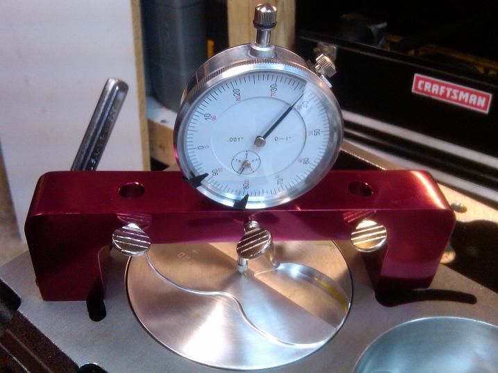
Also installed the crank and two pistons/rods to check my deck height and piston height at TDC with my sweet custom made indicator bridge.
First zero indicator on top of deck surface.

Then reposition bridge over the piston and move it to TDC.

Looks like I'm a little north of 0.0065" out of the hole - was very close on both cylinder banks (within a couple tenths). My main motivation for checking this was to ensure that the shop didn't cut one side more than the other on the clean up cut I had them do. I was fighting repeatability on the gauge when moving it around, it doesn't like being bumped so you have to be gentle picking it up and setting it down. But back calculating some other stuff, this means my deck height is 9.2335", and with 0.040" gaskets my quench is 0.0335".
In the mean time, I torqued down my heads and mains and measured the cylinder bores from the bottom. Everything seemed to check out ok, a little bit of taper in cylinders 1 and 2 but I'll await the seconds shop's opinion before I jump to any conclusions. From my other thread:
Also installed the crank and two pistons/rods to check my deck height and piston height at TDC with my sweet custom made indicator bridge.
First zero indicator on top of deck surface.
Then reposition bridge over the piston and move it to TDC.
Looks like I'm a little north of 0.0065" out of the hole - was very close on both cylinder banks (within a couple tenths). My main motivation for checking this was to ensure that the shop didn't cut one side more than the other on the clean up cut I had them do. I was fighting repeatability on the gauge when moving it around, it doesn't like being bumped so you have to be gentle picking it up and setting it down. But back calculating some other stuff, this means my deck height is 9.2335", and with 0.040" gaskets my quench is 0.0335".