


My 347ci build
Perfect update, exactly what I needed. I have experience with A1. The owner is a nice guy but it will take forever to get your parts back out of there. The guy I have been using for my sbc stuff, Dave Bennett is **** to a fault. I just don't know how much experience he has with an LS1 block.
I used Compstar stuff for a 400 build and it took 2 cranks to get it right. Both had taper, the first was excessive and corner radii didn't match. The second one still had taper but Dave worked his magic. The rods also needed opened up as they were a little too tight for comfort.
I used Compstar stuff for a 400 build and it took 2 cranks to get it right. Both had taper, the first was excessive and corner radii didn't match. The second one still had taper but Dave worked his magic. The rods also needed opened up as they were a little too tight for comfort.
ironman, good luck sourcing a shop. I'll keep this updated with my impressions from LAW once I hear back from them.
With these rods, would you choose to close and hone them at all, or would you let them ride? I'll measure my clearances first but it looks like I've got over a thou on the spec window to work with.
With these rods, would you choose to close and hone them at all, or would you let them ride? I'll measure my clearances first but it looks like I've got over a thou on the spec window to work with.
Last edited by ckpitt55; Mar 9, 2013 at 02:55 PM.
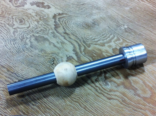
Also figured I'd take a few minutes tonight to post up the dimensions and materials I used to make my cam bearing tool. I would make them but I don't have the means to do so without bugging my friend to let me borrow some time on his lathe. I might be able to make a few in small quantities though if there's enough interest.
raw materials sourced from mcmaster carr (http://www.mcmaster.com):
PN# 9941K31, 2-1/2" hardwood ball
PN# 1610T61, 2-1/2" x 3" lg 6061 Aluminum Rod, temper T6511
PN# 8920K252, 1-1/8" dia x 1' lg low-carbon steel rod
For the o-rings - I ended up using size #131. Took me some trial and error to get the right combination of stretch/compression on the driver head. The 131's were as close as I could get to the perfect amount of interference with the bearing to retain it / protect it, yet allow it to easily slip off as well.
If I were to do it all over again I would have used the 3' handle to allow you to install all bearings from the same direction. I would also suggest that you only hit the end of the handle with a brass hammer. Dead blows would probably also work but you lose that distinct "snappy" impact that is useful when creating or overcoming press fits. I used a steel hammer, and through use the end of the handle mushroomed, preventing the wooden ball from being able to slide off in that direction. Not a dealbreaker but just something I observed.
Cam bearing bore sizes for reference:
1 and 5: 2.3260/2.3280
2 and 4: 2.3161/2.3181
3: 2.3063/2.3083
**As you can see, the #3 bore dictates the size of the driver flange
Cam Bearing OD and ID's (Clevite)
1/5 -- OD: 2.334/2.336 ID: 2.168/2.166
2/4 -- OD: 2.326/2.322 ID: 2.164/2.164
3 -- OD: 2.317 ID: 2.165
I made this drawing in autocad.

Some notes:
*drill a thru hole in the driver for a bolt of your choosing, I counterbored mine to recess the head of the bolt.
*face the mating surfaces of the head and driver so they sit flush when bolted down. drill and tap the handle for whatever bolt you're using
*measure the handle and drill the wooden ball to match, starting with a smaller bit. creep up on the desired size until it's a tight fit. you don't want it to be able to wiggle at all because this is what "self-aligns" to be parallel with the axis of the bore. This makes lining up the driver to the bearing stupid easy on installation as well as removal.
*chamfer / debur all edges that could either contact a bearing, a bearing bore in the block, or an o-ring. you don't want to damage any of these.
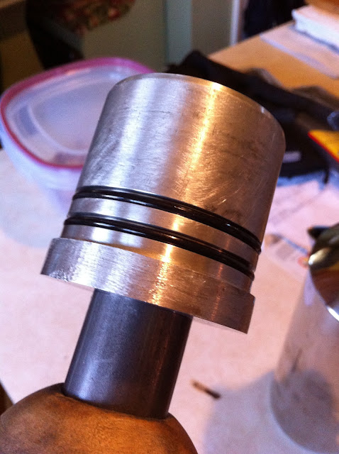
*the spacing of the two o-ring grooves isn't all that critical, but keep them both within about 5/8" of an inch from the bearing contact surface of the driver as the bearing is only about 0.630" wide.
*coat the driver head (and o-rings) with oil prior to throwing on the bearing, protects the bearing from being chaffed
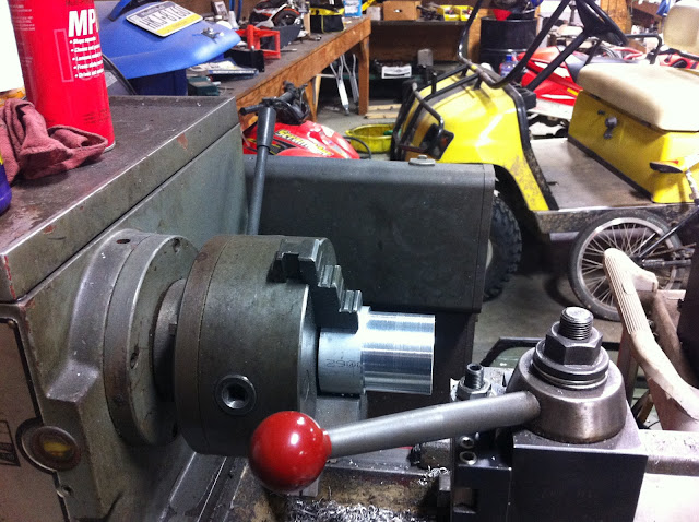
Here's a few pics from when I made mine:
OD turned
O-ring grooves cut
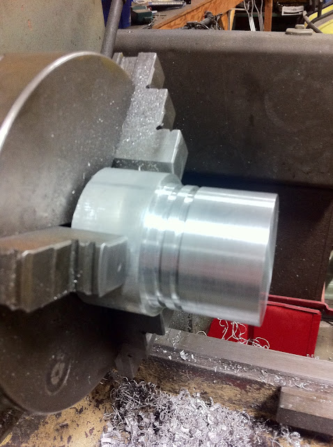
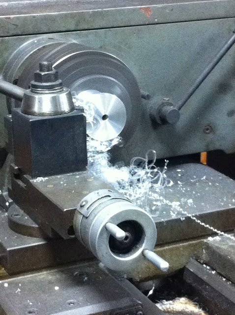
Mating surface of the driver faced
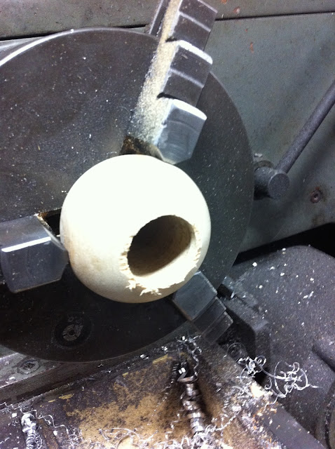
Wooden ball drilled with a spade bit then bored to size
finished tool minus o-rings. doesn't look quite as nice now, but i guess thats to be expected from something you hammer the **** out of on occasion
closeup of the driver head with o-rings installed. take note of the chamfers.
If anyone has any other questions on machining this or using it, feel free to message me.
raw materials sourced from mcmaster carr (http://www.mcmaster.com):
PN# 9941K31, 2-1/2" hardwood ball
PN# 1610T61, 2-1/2" x 3" lg 6061 Aluminum Rod, temper T6511
PN# 8920K252, 1-1/8" dia x 1' lg low-carbon steel rod
For the o-rings - I ended up using size #131. Took me some trial and error to get the right combination of stretch/compression on the driver head. The 131's were as close as I could get to the perfect amount of interference with the bearing to retain it / protect it, yet allow it to easily slip off as well.
If I were to do it all over again I would have used the 3' handle to allow you to install all bearings from the same direction. I would also suggest that you only hit the end of the handle with a brass hammer. Dead blows would probably also work but you lose that distinct "snappy" impact that is useful when creating or overcoming press fits. I used a steel hammer, and through use the end of the handle mushroomed, preventing the wooden ball from being able to slide off in that direction. Not a dealbreaker but just something I observed.
Cam bearing bore sizes for reference:
1 and 5: 2.3260/2.3280
2 and 4: 2.3161/2.3181
3: 2.3063/2.3083
**As you can see, the #3 bore dictates the size of the driver flange
Cam Bearing OD and ID's (Clevite)
1/5 -- OD: 2.334/2.336 ID: 2.168/2.166
2/4 -- OD: 2.326/2.322 ID: 2.164/2.164
3 -- OD: 2.317 ID: 2.165
I made this drawing in autocad.
Some notes:
*drill a thru hole in the driver for a bolt of your choosing, I counterbored mine to recess the head of the bolt.
*face the mating surfaces of the head and driver so they sit flush when bolted down. drill and tap the handle for whatever bolt you're using
*measure the handle and drill the wooden ball to match, starting with a smaller bit. creep up on the desired size until it's a tight fit. you don't want it to be able to wiggle at all because this is what "self-aligns" to be parallel with the axis of the bore. This makes lining up the driver to the bearing stupid easy on installation as well as removal.
*chamfer / debur all edges that could either contact a bearing, a bearing bore in the block, or an o-ring. you don't want to damage any of these.
*the spacing of the two o-ring grooves isn't all that critical, but keep them both within about 5/8" of an inch from the bearing contact surface of the driver as the bearing is only about 0.630" wide.
*coat the driver head (and o-rings) with oil prior to throwing on the bearing, protects the bearing from being chaffed
Here's a few pics from when I made mine:
OD turned
O-ring grooves cut
Mating surface of the driver faced
Wooden ball drilled with a spade bit then bored to size
finished tool minus o-rings. doesn't look quite as nice now, but i guess thats to be expected from something you hammer the **** out of on occasion
closeup of the driver head with o-rings installed. take note of the chamfers.
If anyone has any other questions on machining this or using it, feel free to message me.
One other thing I forgot to add into the notes of that post - if you have the means to do so it'd be handy to machine some wrench flats into the handle. It'd make tightening and removing the driver head a little easier - it seems like it wants to loosen up through use once in a while.
Btw, what kind of lathe do you have? I've been half-assed looking around on craigslist for something I could throw in my garage but haven't had much luck. I would kill for a lathe and a mill - with that combo a proficient machinist can conquer the world lol. Maybe someday, I'll probably spend the rest of my life trying to become proficient, but I plan on enjoying the journey.
Last edited by ckpitt55; Mar 9, 2013 at 09:29 PM.
Thanks for the kind words baron, I try to get a little better with every project I do. And no problem - hope it works out for you! Glad that it's useful to someone. This tool has worked flawlessly for me so far, for about $40 bucks in materials you have something just as good if not better than the $200 proform tools. Along with being able to say you made it yourself!
One other thing I forgot to add into the notes of that post - if you have the means to do so it'd be handy to machine some wrench flats into the handle. It'd make tightening and removing the driver head a little easier - it seems like it wants to loosen up through use once in a while.
Btw, what kind of lathe do you have? I've been half-assed looking around on craigslist for something I could throw in my garage but haven't had much luck. I would kill for a lathe and a mill - with that combo a proficient machinist can conquer the world lol. Maybe someday, I'll probably spend the rest of my life trying to become proficient, but I plan on enjoying the journey.
If I remember on the rods, the small end was right at the low end. So technically they were in spec but I was more comfortable opening them up to nominal.
I talked to the owner at Parco, nice guy but I think he has only heard of the name LS1 but never worked on them.
I talked to the owner at Parco, nice guy but I think he has only heard of the name LS1 but never worked on them.
Yeh I can almost hold the same tolerances with it as I can with the $450,000 Mazak I run at work lol. Yeh the Idea about milling flats on the tool is a good idea I also thought about knurling the handle and polishing it. I'm gonna use stainless steel for the handle. I like nice looking tools ha didn't mean to turn this into a machinist forum
LS1 Tech Stories
The Best V8 Stories One Small Block at Time

Amazing '71 Camaro Restomod Is Modern Muscle Car Under the Skin
Verdad Gallardo
6 Common C5 Corvette Failures and What's Involved In Repairing Them
Pouria Savadkouei
Retro Modern Bandit Pontiac Trans AM Comes With Burt Reynolds' Autograph
Verdad Gallardo
Top 10 Greatest Cadillac V Series Performance Models Ever, Ranked
Pouria Savadkouei
Top 10 Most Powerful Chevy Trucks Ever Made!

Hennessey's New Supercharged Silverado ZR2 Has 700 HP
Verdad Gallardo
Coachbuilt N2A Anteros Is an LS2-Powered C6 Corvette In Italian Clothes
Verdad Gallardo
Awesome K5 Blazer Restomod Comes With C7 Corvette Power
Verdad Gallardo
10 Camaros You Should Never Buy
Yeh I can almost hold the same tolerances with it as I can with the $450,000 Mazak I run at work lol. Yeh the Idea about milling flats on the tool is a good idea I also thought about knurling the handle and polishing it. I'm gonna use stainless steel for the handle. I like nice looking tools ha didn't mean to turn this into a machinist forum
TECH Fanatic

Joined: Jun 2011
Posts: 1,343
Likes: 8
From: Katy, TX
That 0.0003 value you measured would be a combined value, not strictly o-o-R of the bore because the bearing thickness has tolerances too I'm sure. Not a big deal though as I'd expect the higher spots to be reduced during break in.
Ultimately the bearing clearances are the boss, but as of now I don't think the $300 or so it takes to get rods closed and honed is worth reducing the o-o-R a tenth, if that. Pending my clearance measurements I'm just going to run them.
Nope, still waiting. They were supposed to be checking out the block Thurs/Fri and call me Friday to let me know what was going on but I didn't hear from them. I'm gonna call them after work tomorrow if I don't hear from them first.
Kinda getting tired of all of this, I'm at the point where I'm ready to get the engine built.
Kinda getting tired of all of this, I'm at the point where I'm ready to get the engine built.

Little bit of an update finally after a couple of busy weeks scrambling around researching parts, selling parts, hauling my block around, measuring stuff, etc..
Shop Update:
Spoke with the shop today - I'll start off by saying that they seem much more open about what's going on - I spoke directly with the owner / machinist who's working on it. He started with inspection of the hone job the previous shop did on the cylinder bores. While they were pretty good, he felt as though the bores were a little tight in general, reading 0.0037-0.0039" clearance (the minimum is 0.004" for these pistons). These were consistent with my measurements within a few tenths. Given that this motor is being purpose built for the sake of being driven, not babied, he suggested opening them up about a half thou to give me a little more breathing room, while also trying to remove some of the o-o-R that was present in the bores. A little more clearance isn't going to hurt me here, but too little would. I told him to go ahead and do it. I'm not going to haul it back to the other shop and get in a pissing match with them - they're too far away and I don't have the time or the patience to do it. $120 bucks for a "kiss" hone job and wash of the block - pretty reasonable considering the time involved in my opinion. He said he still has to inspect the main bores. More to come on the block.
In other news, converted some of my lifters to solids for various measurements that will happen later on, measured all my crank journals, and also measured my rod bearing clearances.
Converting Stock Hydros to Solid Lifters:
Disassembled

Parts used to shim the lifter perfectly to top of its travel and still allow for the snap ring.
-(2) M4 standard thickness washers
-(1) M6 screw, ~12mm long.
-optional: (1) snap ring for retaining it all. Mcmaster PN# 99142A370. The original wire retainers shot across the garage never to be seen again when I was taking it apart so I needed a replacement.
**Disclaimer: While these are sufficient for retaining everything in this state, I would NOT recommend using these snap rings to retain the lifter innards on ones that you plan to run. They don't seem to have enough spring rate to keep them from shifting around.
Order of assembly:

A pair ready to use for measuring. I wrapped them with some electric tape so I know what they are in the midst of all the other parts I'll have lying around.

Blueprinting the crank:

Reference your mic (with a bit of that old timey vibe)! Excessive handling and fluctuations in room temperature do have an effect!


And here she sleeps once again..

Measurements:
Crank Main and Rod Journals:

Dead nuts on. Measured all the diagonals and they were on as well.
Rod Bearing Clearances (no pics of this process):

The diagram shows where the measurements were taken around the bore. I zeroed my gauge to the average crank journal size for those particular rods and had at it.
Procedurally speaking, I installed the bearings, seated the caps as evenly as I could, torqued them down, then let them sit and stabilize for a day or two before measuring (which wasn't 100% intentional, I was too busy to do it). It's interesting how the measurement parallel with the length of the rod is the tightest (measurement 1), and the clearance gradually increases symmetrically to where it is at Measurement 3. I'm assuming this is intentional by design of the bearings? My rod ends were within a tenth or two o-o-R so I'm assuming that's not what's causing it. Maybe it's the bearing squeeze that's causing this. Is this designed to provide for an "oil pocket" of sorts as the crank rotates or do the tolerances change when the rod is put in tension? Or am I just doing something wrong?
Spec for rod bearing clearances are 0.00248 - 0.003". Seems like I'm in the ball park if you ignore everything but the vertical measurement (Measurement 1).
Thoughts / input / comedic relief are welcome and appreciated. Time for bed
-Chuck
Shop Update:
Spoke with the shop today - I'll start off by saying that they seem much more open about what's going on - I spoke directly with the owner / machinist who's working on it. He started with inspection of the hone job the previous shop did on the cylinder bores. While they were pretty good, he felt as though the bores were a little tight in general, reading 0.0037-0.0039" clearance (the minimum is 0.004" for these pistons). These were consistent with my measurements within a few tenths. Given that this motor is being purpose built for the sake of being driven, not babied, he suggested opening them up about a half thou to give me a little more breathing room, while also trying to remove some of the o-o-R that was present in the bores. A little more clearance isn't going to hurt me here, but too little would. I told him to go ahead and do it. I'm not going to haul it back to the other shop and get in a pissing match with them - they're too far away and I don't have the time or the patience to do it. $120 bucks for a "kiss" hone job and wash of the block - pretty reasonable considering the time involved in my opinion. He said he still has to inspect the main bores. More to come on the block.
In other news, converted some of my lifters to solids for various measurements that will happen later on, measured all my crank journals, and also measured my rod bearing clearances.
Converting Stock Hydros to Solid Lifters:
Disassembled
Parts used to shim the lifter perfectly to top of its travel and still allow for the snap ring.
-(2) M4 standard thickness washers
-(1) M6 screw, ~12mm long.
-optional: (1) snap ring for retaining it all. Mcmaster PN# 99142A370. The original wire retainers shot across the garage never to be seen again when I was taking it apart so I needed a replacement.
**Disclaimer: While these are sufficient for retaining everything in this state, I would NOT recommend using these snap rings to retain the lifter innards on ones that you plan to run. They don't seem to have enough spring rate to keep them from shifting around.
Order of assembly:
A pair ready to use for measuring. I wrapped them with some electric tape so I know what they are in the midst of all the other parts I'll have lying around.
Blueprinting the crank:
Reference your mic (with a bit of that old timey vibe)! Excessive handling and fluctuations in room temperature do have an effect!
And here she sleeps once again..
Measurements:
Crank Main and Rod Journals:
Dead nuts on. Measured all the diagonals and they were on as well.
Rod Bearing Clearances (no pics of this process):
The diagram shows where the measurements were taken around the bore. I zeroed my gauge to the average crank journal size for those particular rods and had at it.
Procedurally speaking, I installed the bearings, seated the caps as evenly as I could, torqued them down, then let them sit and stabilize for a day or two before measuring (which wasn't 100% intentional, I was too busy to do it). It's interesting how the measurement parallel with the length of the rod is the tightest (measurement 1), and the clearance gradually increases symmetrically to where it is at Measurement 3. I'm assuming this is intentional by design of the bearings? My rod ends were within a tenth or two o-o-R so I'm assuming that's not what's causing it. Maybe it's the bearing squeeze that's causing this. Is this designed to provide for an "oil pocket" of sorts as the crank rotates or do the tolerances change when the rod is put in tension? Or am I just doing something wrong?
Spec for rod bearing clearances are 0.00248 - 0.003". Seems like I'm in the ball park if you ignore everything but the vertical measurement (Measurement 1).
Thoughts / input / comedic relief are welcome and appreciated. Time for bed
-Chuck
Last edited by ckpitt55; Mar 20, 2013 at 12:26 AM.
You're on a roll man! Your measurements on your rod bearings seems right. I've always heard you want your bearing to have MORE clearance along the parting line of your rod. Check out www.aera.org they have some info on bearing clearances. I'm still in the hunt for a 6.0 that I'm chompin at the bit to work on!
You're on a roll man! Your measurements on your rod bearings seems right. I've always heard you want your bearing to have MORE clearance along the parting line of your rod. Check out www.aera.org they have some info on bearing clearances. I'm still in the hunt for a 6.0 that I'm chompin at the bit to work on!


Yes, that is intentionally designed into the bearings. It's a "well" if you will for oil to accumulated, get picked up by the surface of the crank journal, and squeezed into the tighter clearance to form a hydrodynamic wedge. This is what keeps your bearings from meeting your crank. The 12 and 6 o'clock measurement is what you need to be concerned with most.
Yes, that is intentionally designed into the bearings. It's a "well" if you will for oil to accumulated, get picked up by the surface of the crank journal, and squeezed into the tighter clearance to form a hydrodynamic wedge. This is what keeps your bearings from meeting your crank. The 12 and 6 o'clock measurement is what you need to be concerned with most.