

Avoid new style ls2 lifter trays
 08-13-2016, 02:46 AM
#1


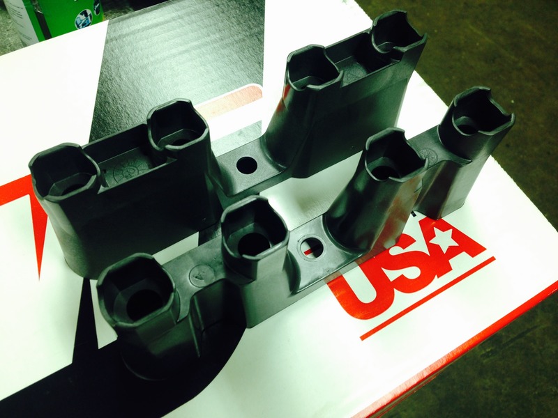
Am not on here much anymore, but had to post this. Checked the new style ls lifter trays & each leg responsible for retaining the flats on the lifters are spreading. The lifters fall right out of them because they have gotten so wide. Am sure lifters would have eventually spun.
Reason...the rib that extends from flat to flat on each side of the dual lifter retainer has been eliminated on the new style design. These ribs strengthened the retainers on the original design. Removing the ribs has weakened the wall of the retainer that contacts the flat and now allows it to spread.
Put older lifter trays back in. Retainer flats were still tight. Should have never "upgraded" to new style.
No need for anyone to state, "thats why i only use $20,000 link bar style lifters (cheap insurance, of course)."
It wont help this thread. Besides, we already know that your engine is perfect...built inside a vacuum chamber & all that.

The following users liked this post:
DiabolicLoco (12-24-2023)
 08-13-2016, 08:54 AM
#3
Am not on here much anymore, but had to post this. Checked the new style ls lifter trays & each leg responsible for retaining the flats on the lifters are spreading. The lifters fall right out of them because they have gotten so wide. Am sure lifters would have eventually spun.
Reason...the rib that extends from flat to flat on each side of the dual lifter retainer has been eliminated on the new style design. These ribs strengthened the retainers on the original design. Removing the ribs has weakened the wall of the retainer that contacts the flat and now allows it to spread.
Put older lifter trays back in. Retainer flats were still tight. Should have never "upgraded" to new style.
No need for anyone to state, "thats why i only use $20,000 link bar style lifters (cheap insurance, of course)."
It wont help this thread. Besides, we already know that your engine is perfect...built inside a vacuum chamber & all that.
Reason...the rib that extends from flat to flat on each side of the dual lifter retainer has been eliminated on the new style design. These ribs strengthened the retainers on the original design. Removing the ribs has weakened the wall of the retainer that contacts the flat and now allows it to spread.
Put older lifter trays back in. Retainer flats were still tight. Should have never "upgraded" to new style.
No need for anyone to state, "thats why i only use $20,000 link bar style lifters (cheap insurance, of course)."
It wont help this thread. Besides, we already know that your engine is perfect...built inside a vacuum chamber & all that.
08-13-2016, 09:40 AM
#4
Am typing on phone & couldnt tag kcs comment to combine reply. So, will reply here.
Yes, trays are supposed to hold snugly. Once there is play, bore spreads & lifter spins. These were nice & snug when installed. Now most bores have enough play in them to slightly twist lifter.
Gm should have not eliminated the boxed off design found on original tray design. New design looks like two chicken legs flapping in the wind. Previous design had skirts (ribs) tying legs together, boxed design.
08-13-2016, 10:49 AM
#5
Less than 1000 miles since installed.
Am typing on phone & couldnt tag kcs comment to combine reply. So, will reply here.
Yes, trays are supposed to hold snugly. Once there is play, bore spreads & lifter spins. These were nice & snug when installed. Now most bores have enough play in them to slightly twist lifter.
Gm should have not eliminated the boxed off design found on original tray design. New design looks like two chicken legs flapping in the wind. Previous design had skirts (ribs) tying legs together, boxed design.
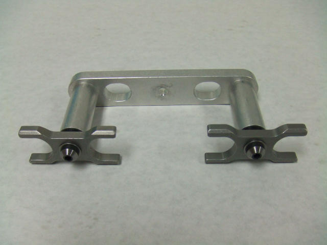
I have both styles in front of me for anyone who needs a visual aid:
 08-14-2016, 06:16 AM
#6
May sound paranoid, but also attentive. This car has seen road course use since 2003; the ultimate engine punishment. Since the beginning, have never had trays open up this much & this set hasn't even been on track. I wont use 'em again.
Trending Topics
08-15-2016, 03:35 AM
#8

This is ridiculous. Thanks for the heads up. I have several early ls1 engines which I can reuse the good lifter guides from. Back in 2005, my heads/cam ls1 worked flawlessly for over 50,000 miles, lost count how many WOT and 1/4 mile runs, 7200rpm shifts. And street victories, cross country trips.
Always need to be on the look out these days for the cheap chinese junk.
Always need to be on the look out these days for the cheap chinese junk.
08-15-2016, 09:22 AM
#10

Have you seen any lifters spin? I agree the trays get loose, even the LS1 trays would get loose and allow a lifter to fall out, but I've never seen one with enough slop to allow the lifter to spin. Sounds a little paranoid.
I have both styles in front of me for anyone who needs a visual aid:
I have both styles in front of me for anyone who needs a visual aid:
are these the only 2 choices for LS2/LS3 builds? I mean, using OEM hardware, you have to use an OEM Lifter and one of these two kinds of retainer?
08-15-2016, 09:55 AM
#11
Your other option is a tie bar lifter.
 08-15-2016, 02:52 PM
#15

Those trays DO NOT repeat DO NOT hold the lifter from turning in the bores! They are GUIDES, the lifter roller against the cam holds the lifter in place. NOTHING MORE, those plastic guides are only there to hold the lifters in place and to provide lubrication.
They could be made from paper as long as the held the lifter in place until the roller is under tension on the cam. < READ IT BELIEVE IT MOVE ON !
They could be made from paper as long as the held the lifter in place until the roller is under tension on the cam. < READ IT BELIEVE IT MOVE ON !
08-15-2016, 04:33 PM
#17
I'm not saying the valve train is bullet proof and a lifter couldn't turn in a bore from valve float high r's etc. What I'm saying is the plastic GUIDES are to hold the lifters in place under stock conditions. If the lifters start to loft off the cam expecting a piece of plastic to try and control this is a fantasy. That's why god invented link bar lifters for extreme conditions.
08-15-2016, 11:27 PM
#18
Those trays DO NOT repeat DO NOT hold the lifter from turning in the bores! They are GUIDES, the lifter roller against the cam holds the lifter in place. NOTHING MORE, those plastic guides are only there to hold the lifters in place and to provide lubrication.
They could be made from paper as long as the held the lifter in place until the roller is under tension on the cam. < READ IT BELIEVE IT MOVE ON !
They could be made from paper as long as the held the lifter in place until the roller is under tension on the cam. < READ IT BELIEVE IT MOVE ON !
This is how the lifter trays are loaded. Sketch attached to give a basic view of what is being described. Don't know why it's upside down, just rotate to view.
The trays are under constant load anytime the rockers are in motion, except @ TDC. There is a radial load applied to the rocker tip. That load becomes a vector (angular load) that varies as the load moves across the tip. Vectors have a vertical & horizontal component. For this reason, the walls of the tray retainers are under constant load any time the rockers are moving (except @ TDC). The load is reduced by the coefficient of friction between the retainer, lifter & the effect of oil. The load is small, but is in motion (dynamic). For this reason it is an inertial load & the retainer has to be designed to absorb the energy without major fatigue. Am sure that GM has a computer model to look @ this. Calculation could also determine @ which point link bars are required over retaining trays.
From what was found in my engine, it appears that the "new" LS2 trays are not as good @ supporting these loads when they are increased by the use of heavy dual springs & higher RPMs. It may be that in stock applications, the new retainers are fine. Mine grew large enough to be able to slightly hand twist a rocker in some of the retainer bores. So, the same can be happening in the engine. The bores were only going to grow larger until the lifters were able to turn enough to cause a major problem. It may not look like much between the old & new designs, but the older version is far better @ supporting the loads in the retainer bores.
Anyone using the LS2 style in conjunction w/ heavy springs & @ higher than stock RPMs should just know to pay attention to odd sounds. Stock applications are probably fine. This may also be a cause of roller or lobe failures that was previously not considered. I don't know for sure. Have posted what has been found along w/ a basic description of loading in the area. Like w/ anything, one can choose to use the info or not to use it.

