


Can a heads ports work like a golfball?
Thread Starter
TECH Veteran
iTrader: (12)
Joined: Dec 2004
Posts: 4,354
Likes: 0
From: Rockville, MD
weird huh? heres my reasoning. a golf ball travels the way it does because of its surface. the pits on it give it a longer flight and faster flight compared to one of same composition yet smooth surface. now what if the intake ports in a head were designed like the suface of the modern golf ball? would it increase velocity in a measureable way?
I guess the question is a golf ball surface less restricted than a smooth surface, I would say no. I think the ball cuts air better, but I think that would cause more turbulence than flow, because a golf ***** surface changes pressures allowing it to create is own lift. thus creating or changing air flow.
hmm I just spit this out by I am a huge BSer so I have no idea is what I am saying. But you better call the patent office, or maybe I already did you never know. but the above sounds logical
hmm I just spit this out by I am a huge BSer so I have no idea is what I am saying. But you better call the patent office, or maybe I already did you never know. but the above sounds logical
Thread Starter
TECH Veteran
iTrader: (12)
Joined: Dec 2004
Posts: 4,354
Likes: 0
From: Rockville, MD
Originally Posted by daryl2cb@yahoo.com
I guess the question is a golf ball surface less restricted than a smooth surface, I would say no. I think the ball cuts air better, but I think that would cause more turbulence than flow, because a golf ***** surface changes pressures allowing it to create is own lift. thus creating or changing air flow.
hmm I just spit this out by I am a huge BSer so I have no idea is what I am saying. But you better call the patent office, or maybe I already did you never know. but the above sounds logical
hmm I just spit this out by I am a huge BSer so I have no idea is what I am saying. But you better call the patent office, or maybe I already did you never know. but the above sounds logical
The dimples act to create turbulence in the layer of air around the ball, which reduces drag. I'm not a physicist, nor do I pretend to be right, but I think the technology would apply more to an object moving through air, not air through an object.
Trending Topics
NOPE. Without getting into a big discussion about physics, the dimples create lift and sort of as already stated, turbulance.
They are designed to keep the ball in the air.
Different theory.
For the rest of you. your ball doesn't go straight because you have too much L.O.F.T..
Lack Of F'n Talent - it isn't the ball.
That's not suppose to offend, it's supposed to be a joke son, a joke.
They are designed to keep the ball in the air.
Different theory.
For the rest of you. your ball doesn't go straight because you have too much L.O.F.T..
Lack Of F'n Talent - it isn't the ball.
That's not suppose to offend, it's supposed to be a joke son, a joke.
LS1 Tech Stories
The Best V8 Stories One Small Block at Time

Gas Monkey Built a 6-Wheel Ferrari Testarossa With a Corvette LT4 Engine
Verdad Gallardo
7 Most Reliable High-Performance Engines GM Has Ever Built
Verdad Gallardo
Amazing '71 Camaro Restomod Is Modern Muscle Car Under the Skin
Verdad Gallardo
6 Common C5 Corvette Failures and What's Involved In Repairing Them
Pouria Savadkouei
Retro Modern Bandit Pontiac Trans AM Comes With Burt Reynolds' Autograph
Verdad Gallardo
Top 10 Greatest Cadillac V Series Performance Models Ever, Ranked
Pouria Savadkouei
Top 10 Most Powerful Chevy Trucks Ever Made!

Hennessey's New Supercharged Silverado ZR2 Has 700 HP
Verdad Gallardo
Coachbuilt N2A Anteros Is an LS2-Powered C6 Corvette In Italian Clothes
Verdad Gallardo As stated, the dimples are keeping the boudary layer attached longer, reducing drag on the ball. They apparently figured this out years ago when the ***** were smooth, and people realized their beat-up, used golf ***** were flying farther than new ones out of the box.
From my understanding, turbulence in the port is not a good thing, which is what the dimples would cause if I'm not mistaken.
From my understanding, turbulence in the port is not a good thing, which is what the dimples would cause if I'm not mistaken.
Yeah, the only place your looking for turbulence is in the combustion chanber, so the a/f mixture atomizes well. any tubulence in either the intake or exhaust tracts cause the air/gases to slow down, decreasing efficiency.
When you hit a golf ball correctly there is a backspin on it. As it is going through the air the air passing underneath it is traveling faster than the air traveling over it. The air traveling under it causes more pressure to be built up in the pockets below the center of revolution than on the top. More lift is created this way. As to how this would relate to head port I don't see how it would help other than creating more turbulence in it and that would be counter productive. Maybe if you put a spinning golf ball IN the port...

if a intake port where too be smooth with dimples i think there would be turbulance . whats the theory if you hit a golf ball in the rain? that would be kinda close to a intake port with fuel in it
Also the injectors already atomize the fuel when they pulse..so if you had the ports dimpled instead of smooth i think the atomized fuel would bounce around.
OUCH MY BRAIN
Also the injectors already atomize the fuel when they pulse..so if you had the ports dimpled instead of smooth i think the atomized fuel would bounce around.
OUCH MY BRAIN
Last edited by 8GTOKLR; Mar 9, 2006 at 12:15 PM.


Think of a bird. It can coast in the air without flapping because of the lift created by it's wings and the angle of them. (creating turbulence) The angle also produces drag but there aren't after speed they are trying to glide. (Golf ball principle. Ever notice that when they dive they are in a tucked position to minimize drag and increase speed. We are trying to increase the speed of the air moving through the heads not create drag. So I think it would have a negative effect on air flow.
My .02 and a bad analogy.
My .02 and a bad analogy.


actually, this theory is already applied by most head porters.
see, if you polish the intake runners of a conventional wet flow head or intake (like a SBC) smooth, the fuel wets the walls and falls out of suspension.
but by leaving the surface slightly rough, the turbulence made by the rough texture helps keep the fuel off the walls, and in suspension.
on newer motors, such as our genIII+s we dont worry about that as much, since the injector is basically spraying into the chamber at the back of the valve, and its a sequential injection system.. not a batchfire...
Golf Ball Dimples & Drag
The dimples of a typical golf ball
Before explaining the purpose of dimples, we first need to understand the aerodynamic properties of a sphere. Let us start by looking at a smooth sphere without any dimples, like a ping-pong ball. If we lived in an ideal world without any friction, the air flowing around a smooth sphere would behave like that shown in the following diagram. In this figure, the angle q represents position along the surface of the sphere. The leading edge of the sphere that first encounters the incoming airflow is at q=0� while the trailing edge is at q=180�. A position of q=90� is the top of the sphere, q=270� is the bottom, and q=360� brings us back around to the leading edge. Note that in this ideal situation, the air flowing around the sphere forms a perfectly symmetrical pattern. The streamline pattern around the front face, from 270� up to 90�, is the same as that around the back face, from 90� down to 270�.
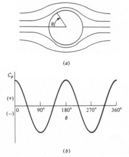
(a) Ideal frictionless flowfield around a sphere and (b) the resulting pressure distribution
The lower half of this figure also displays the pressure distribution around the surface of the sphere, as represented by the non-dimensional pressure coefficient Cp. Positive (+) values of Cp indicate high pressure while negative (-) values indicate low pressure. It is the differences between high-pressure regions and low-pressure regions that create aerodynamic forces on a body, like lift and drag.
However, this ideal flow pattern tells us something very interesting. Notice that the pressure at the front of the sphere, or q=0�, is very high. This high pressure indicates that the incoming air impacting against the front face creates a drag force. Nonetheless, the pressure at the back of the sphere, or q=180�, is also high and identical to that at the front. This high pressure actually creates a thrust, or negative drag, that cancels out the drag on the front of the sphere. In other words, this theoretical situation tells us that there is no drag on a sphere!
Early aerodynamics researchers were quite puzzled by this theoretical result because it contradicted experimental measurements indicating that a sphere does generate drag. The conflict between theory and experiment was one of the great mysteries of the late 19th century that became known as d'Alembert's Paradox, named for famous French mathematician and physicist Jean le Rond d'Alembert (1717-1783) who first discovered the discrepancy.
The reason d'Alembert's ideal theory failed to explain the true aerodynamic behavior of a sphere is that he ignored the influence of friction in his calculations. The actual flowfield around a sphere looks much different than his theory predicts because friction causes a phenomenon known as flow separation. We can better understand this effect by studying the following diagram of the actual flow around a smooth sphere. Here we see that the flowfield around the sphere is no longer symmetrical. Whereas the flow around the ideal sphere continued to follow the surface along the entire rear face, the actual flow no longer does so. When the airflow follows along the surface, we say that the flow is attached. The point at which the flow breaks away from the surface is called the separation point, and the flow downstream of this point is referred to as separated. The region of separated flow is dominated by unsteady, recirculating vortices that create a wake.
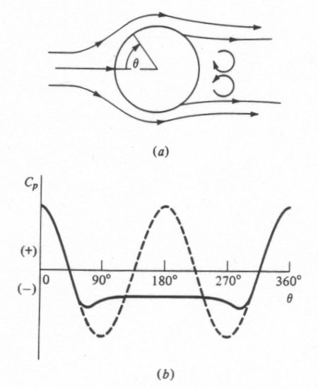
(a) Actual separated flowfield around a sphere and (b) the resulting pressure distribution
The cause of this separation can be seen in the above pressure distribution around the sphere. As the flow moves downstream from the q=90� or q=270� position, it encounters an increasing pressure. Whenever a flow encounters increasing pressure, we say that it experiences an adverse pressure gradient. The change in pressure is called adverse because it causes the airflow to slow down and lose momentum. As the pressure continues to increase, the flow continues to slow down until it reaches a speed of zero. It is at this point that the air no longer has any forward momentum, so it separates from the surface.
Once the flow separates from the surface, it no longer results in the ideal pressure distribution shown as the dashed line. Instead, a separated flow creates a region of low pressure in the wake. We see this behavior over the rear face of the sphere from 90� < q < 270�. Here, the actual pressure distribution, shown as the solid line, remains negative, in contrast to the ideal prediction. The pressure on the front face is still high, however, just as it was for the ideal sphere. Since the pressure is now much higher on the front face than it is on the rear face, the net result is a drag force exerted on the sphere. By accounting for the effect of friction, theory and experiment come into agreement and d'Alembert's Paradox is reconciled.
This explanation leads us to an important conclusion: the drag on a sphere is dominated by the flow separation over its rear face. If we could somehow minimize that separation, the drag experienced by the sphere would be significantly reduced. We can see this effect in experimental data, like that pictured below.
Variation of drag coefficient with Reynolds number for a sphere
This diagram illustrates how the drag of a sphere varies with the Reynolds number. Reynolds number (Re) is an important non-dimensional parameter that is used to relate the size of an object to the flow conditions it experiences, and is defined by the equation

where
What is it about this particular Reynolds number that causes such a large reduction in drag? It turns out that it is at this critical point that the air flowing around the sphere makes an important change. We have already discussed the concept of flow separation. One of the key factors affecting flow separation is the behavior of the boundary layer. The boundary layer is a thin layer of air that lies very close to the surface of a body in motion. It is within this layer that the adverse pressure gradient develops that causes the airflow to separate from the surface.
At low Reynolds numbers, the boundary layer remains very smooth and is called laminar. Laminar boundary layers are normally very desirable because they reduce drag on most shapes. Unfortunately, laminar boundary layers are also very fragile and separate from the surface of a body very easily when they encounter an adverse pressure gradient. This separated flow is what causes the drag to remain so high below the critical Reynolds number.
At that Reynolds number, however, the boundary layer switches from being laminar to turbulent. The location at which this change in the boundary layer occurs is called the transition point. A turbulent boundary layer causes mixing of the air near the surface that normally results in higher drag. However, the advantage of turbulence is that it speeds up the airflow and gives it more forward momentum. As a result, the boundary layer resists the adverse pressure gradient much longer before it separates from the surface.
Flow separation on a sphere with a laminar versus turbulent boundary layer
- Can you explain why a golf ball has dimples? If dimples reduce drag, why don't we see this surface feature on other aerodynamic shapes like airplane wings?
- Brent Obst, Andrew
The dimples of a typical golf ball
Before explaining the purpose of dimples, we first need to understand the aerodynamic properties of a sphere. Let us start by looking at a smooth sphere without any dimples, like a ping-pong ball. If we lived in an ideal world without any friction, the air flowing around a smooth sphere would behave like that shown in the following diagram. In this figure, the angle q represents position along the surface of the sphere. The leading edge of the sphere that first encounters the incoming airflow is at q=0� while the trailing edge is at q=180�. A position of q=90� is the top of the sphere, q=270� is the bottom, and q=360� brings us back around to the leading edge. Note that in this ideal situation, the air flowing around the sphere forms a perfectly symmetrical pattern. The streamline pattern around the front face, from 270� up to 90�, is the same as that around the back face, from 90� down to 270�.
(a) Ideal frictionless flowfield around a sphere and (b) the resulting pressure distribution
The lower half of this figure also displays the pressure distribution around the surface of the sphere, as represented by the non-dimensional pressure coefficient Cp. Positive (+) values of Cp indicate high pressure while negative (-) values indicate low pressure. It is the differences between high-pressure regions and low-pressure regions that create aerodynamic forces on a body, like lift and drag.
However, this ideal flow pattern tells us something very interesting. Notice that the pressure at the front of the sphere, or q=0�, is very high. This high pressure indicates that the incoming air impacting against the front face creates a drag force. Nonetheless, the pressure at the back of the sphere, or q=180�, is also high and identical to that at the front. This high pressure actually creates a thrust, or negative drag, that cancels out the drag on the front of the sphere. In other words, this theoretical situation tells us that there is no drag on a sphere!
Early aerodynamics researchers were quite puzzled by this theoretical result because it contradicted experimental measurements indicating that a sphere does generate drag. The conflict between theory and experiment was one of the great mysteries of the late 19th century that became known as d'Alembert's Paradox, named for famous French mathematician and physicist Jean le Rond d'Alembert (1717-1783) who first discovered the discrepancy.
The reason d'Alembert's ideal theory failed to explain the true aerodynamic behavior of a sphere is that he ignored the influence of friction in his calculations. The actual flowfield around a sphere looks much different than his theory predicts because friction causes a phenomenon known as flow separation. We can better understand this effect by studying the following diagram of the actual flow around a smooth sphere. Here we see that the flowfield around the sphere is no longer symmetrical. Whereas the flow around the ideal sphere continued to follow the surface along the entire rear face, the actual flow no longer does so. When the airflow follows along the surface, we say that the flow is attached. The point at which the flow breaks away from the surface is called the separation point, and the flow downstream of this point is referred to as separated. The region of separated flow is dominated by unsteady, recirculating vortices that create a wake.
(a) Actual separated flowfield around a sphere and (b) the resulting pressure distribution
The cause of this separation can be seen in the above pressure distribution around the sphere. As the flow moves downstream from the q=90� or q=270� position, it encounters an increasing pressure. Whenever a flow encounters increasing pressure, we say that it experiences an adverse pressure gradient. The change in pressure is called adverse because it causes the airflow to slow down and lose momentum. As the pressure continues to increase, the flow continues to slow down until it reaches a speed of zero. It is at this point that the air no longer has any forward momentum, so it separates from the surface.
Once the flow separates from the surface, it no longer results in the ideal pressure distribution shown as the dashed line. Instead, a separated flow creates a region of low pressure in the wake. We see this behavior over the rear face of the sphere from 90� < q < 270�. Here, the actual pressure distribution, shown as the solid line, remains negative, in contrast to the ideal prediction. The pressure on the front face is still high, however, just as it was for the ideal sphere. Since the pressure is now much higher on the front face than it is on the rear face, the net result is a drag force exerted on the sphere. By accounting for the effect of friction, theory and experiment come into agreement and d'Alembert's Paradox is reconciled.
This explanation leads us to an important conclusion: the drag on a sphere is dominated by the flow separation over its rear face. If we could somehow minimize that separation, the drag experienced by the sphere would be significantly reduced. We can see this effect in experimental data, like that pictured below.
Variation of drag coefficient with Reynolds number for a sphere
This diagram illustrates how the drag of a sphere varies with the Reynolds number. Reynolds number (Re) is an important non-dimensional parameter that is used to relate the size of an object to the flow conditions it experiences, and is defined by the equation
where
- r = atmospheric density
V� = velocity
l = reference length (in the case of a sphere, this variable is defined as the diameter)
m = viscosity (or friction)
What is it about this particular Reynolds number that causes such a large reduction in drag? It turns out that it is at this critical point that the air flowing around the sphere makes an important change. We have already discussed the concept of flow separation. One of the key factors affecting flow separation is the behavior of the boundary layer. The boundary layer is a thin layer of air that lies very close to the surface of a body in motion. It is within this layer that the adverse pressure gradient develops that causes the airflow to separate from the surface.
At low Reynolds numbers, the boundary layer remains very smooth and is called laminar. Laminar boundary layers are normally very desirable because they reduce drag on most shapes. Unfortunately, laminar boundary layers are also very fragile and separate from the surface of a body very easily when they encounter an adverse pressure gradient. This separated flow is what causes the drag to remain so high below the critical Reynolds number.
At that Reynolds number, however, the boundary layer switches from being laminar to turbulent. The location at which this change in the boundary layer occurs is called the transition point. A turbulent boundary layer causes mixing of the air near the surface that normally results in higher drag. However, the advantage of turbulence is that it speeds up the airflow and gives it more forward momentum. As a result, the boundary layer resists the adverse pressure gradient much longer before it separates from the surface.
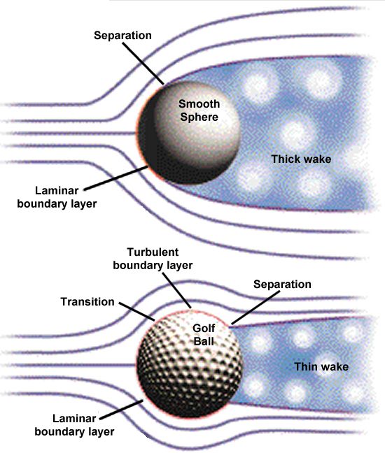
Flow separation on a sphere with a laminar versus turbulent boundary layer
The difference in the flowfields around a smooth sphere and a rough, or dimpled, sphere can be seen above. Since the laminar boundary layer around the smooth sphere separates so rapidly, it creates a very large wake over the entire rear face. This large wake maximizes the region of low pressure and, therefore, results in the maximum difference in pressure between the front and rear faces. As we have seen, this difference creates a large drag like that seen below the transition Reynolds number.
The transition to a turbulent boundary layer, on the other hand, adds energy to the flow allowing it to remain attached to the surface of the sphere further aft. Since separation is delayed, the resulting wake is much narrower. This thin wake reduces the low-pressure region on the rear face and reduces the difference in pressure between the front and back of the sphere. This smaller difference in pressure creates a smaller drag force comparable to that seen above the transition Reynolds number.
These results tell us that causing a turbulent boundary layer to form on the front surface significantly reduces the sphere's drag. For a given sphere diameter, a designer has only two options encourage this transition, either 1) increase the speed of the flow over the sphere to increase the Reynolds number beyond transition or 2) make the surface rough in order to create turbulence. The latter case is often referred to as "tripping" the boundary layer.
In the case of a golf ball, increasing the speed is not an option since a golfer can only swing the club so fast, and this velocity is insufficient to exceed the transition Reynolds number. That leaves tripping the boundary layer as the only realistic alternative to reducing the drag on a golf ball. The purpose of the dimples is to do just that--to create a rough surface that promotes an early transition to a turbulent boundary layer. This turbulence helps the flow remain attached to the surface of the ball and reduces the size of the separated wake so as to reduce the drag it generates in flight. When the drag is reduced, the ball flies farther. Some golf ball manufacturers have even started including dimples with sharp corners rather than circular dimples since research indicates that these polygonal shapes reduce drag even more.

Comparison of flow separation and drag on blunt and streamlined shapes
The reason we do not see dimples on other shapes, like wings, is that these particular forms of boundary layer trips only work well on a blunt body like a sphere or a cylinder. The most dominant form of drag on these kinds of shapes is caused by pressure, as we have seen throughout this discussion. More streamlined shapes like the airfoils used on wings are dominated by a different kind of drag called skin friction drag. These streamlined bodies, like that pictured above, have a teardrop shape that creates a much more gradual adverse pressure gradient. This less severe gradient promotes attached flow much further along the body that eliminates flow separation, or at least delays it until very near the trailing edge. The resulting wake is therefore very small and generates very little pressure drag.
However, there do exist other types of devices commonly used on wings that create a similar effect to the dimples used on golf *****. Though these wing devices also create turbulence in order to delay flow separation, the purpose is not to decrease drag but to increase lift. One of the most popular of these devices is the vortex generator.
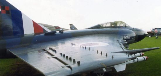
A Gloster Javelin showing the three sets of vortex generators located along the outer portion of the wing
Vortex generators are often placed along the outer portion of a wing in order to promote a turbulent boundary layer that adds forward momentum to the flow. As in the case of the golf ball, this turbulent boundary layer helps the flow overcome an adverse pressure gradient and remain attached to the surface longer than it would otherwise.
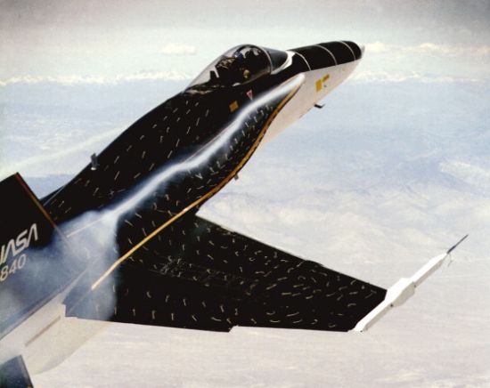
Flow visualization test on the leading edge extension of an F-18 A related device that is most commonly used on high performance fighters is the leading edge extension (LEX), like that shown above. Both the vortex generator and the LEX are primarily used to delay the flow separation that occurs when operating at high angles of attack near stall. As angle of attack increases, the adverse pressure gradient along the airfoil becomes increasingly stronger. Once the stall angle is reached, the gradient becomes so strong that it forces the flow to separate resulting in a loss of lift or control effectiveness. The advantage of devices like vortex generators and leading edge extensions is that they force the flow to remain attached at higher angles of attack and increase the stall angle. This improvement gives planes likes fighters greater maneuverability while increasing the safety of commercial airliners.
- answer by Jeff Scott, 13 February 2005
The transition to a turbulent boundary layer, on the other hand, adds energy to the flow allowing it to remain attached to the surface of the sphere further aft. Since separation is delayed, the resulting wake is much narrower. This thin wake reduces the low-pressure region on the rear face and reduces the difference in pressure between the front and back of the sphere. This smaller difference in pressure creates a smaller drag force comparable to that seen above the transition Reynolds number.
These results tell us that causing a turbulent boundary layer to form on the front surface significantly reduces the sphere's drag. For a given sphere diameter, a designer has only two options encourage this transition, either 1) increase the speed of the flow over the sphere to increase the Reynolds number beyond transition or 2) make the surface rough in order to create turbulence. The latter case is often referred to as "tripping" the boundary layer.
In the case of a golf ball, increasing the speed is not an option since a golfer can only swing the club so fast, and this velocity is insufficient to exceed the transition Reynolds number. That leaves tripping the boundary layer as the only realistic alternative to reducing the drag on a golf ball. The purpose of the dimples is to do just that--to create a rough surface that promotes an early transition to a turbulent boundary layer. This turbulence helps the flow remain attached to the surface of the ball and reduces the size of the separated wake so as to reduce the drag it generates in flight. When the drag is reduced, the ball flies farther. Some golf ball manufacturers have even started including dimples with sharp corners rather than circular dimples since research indicates that these polygonal shapes reduce drag even more.
Comparison of flow separation and drag on blunt and streamlined shapes
The reason we do not see dimples on other shapes, like wings, is that these particular forms of boundary layer trips only work well on a blunt body like a sphere or a cylinder. The most dominant form of drag on these kinds of shapes is caused by pressure, as we have seen throughout this discussion. More streamlined shapes like the airfoils used on wings are dominated by a different kind of drag called skin friction drag. These streamlined bodies, like that pictured above, have a teardrop shape that creates a much more gradual adverse pressure gradient. This less severe gradient promotes attached flow much further along the body that eliminates flow separation, or at least delays it until very near the trailing edge. The resulting wake is therefore very small and generates very little pressure drag.
However, there do exist other types of devices commonly used on wings that create a similar effect to the dimples used on golf *****. Though these wing devices also create turbulence in order to delay flow separation, the purpose is not to decrease drag but to increase lift. One of the most popular of these devices is the vortex generator.
A Gloster Javelin showing the three sets of vortex generators located along the outer portion of the wing
Vortex generators are often placed along the outer portion of a wing in order to promote a turbulent boundary layer that adds forward momentum to the flow. As in the case of the golf ball, this turbulent boundary layer helps the flow overcome an adverse pressure gradient and remain attached to the surface longer than it would otherwise.
Flow visualization test on the leading edge extension of an F-18 A related device that is most commonly used on high performance fighters is the leading edge extension (LEX), like that shown above. Both the vortex generator and the LEX are primarily used to delay the flow separation that occurs when operating at high angles of attack near stall. As angle of attack increases, the adverse pressure gradient along the airfoil becomes increasingly stronger. Once the stall angle is reached, the gradient becomes so strong that it forces the flow to separate resulting in a loss of lift or control effectiveness. The advantage of devices like vortex generators and leading edge extensions is that they force the flow to remain attached at higher angles of attack and increase the stall angle. This improvement gives planes likes fighters greater maneuverability while increasing the safety of commercial airliners.
- answer by Jeff Scott, 13 February 2005