


ITB manifold. Need opinions.
I just got my hands on a used LS2 block and a set of LS3 heads that I�ll be using for an upcoming project. Yesterday, while thinking about which way to go with this engine, the ideal of 433+ cubic inches and an ITB manifold jumped into my head. Seeing how ITB manifolds are extremely pricey I decided I�ll take a crack at making one myself. PLEASE SPARE ME THE �IT�S TOO HARD� OR �IT�LL BE CHEAPER IN THE LONG RUN TO JUST BUY ONE�, ETC. I�m doing this mainly for experimental and fun purposes so no need for that. Since I�m doing this myself if it doesn�t work out the only money I�ll be losing is on materials. I can always resell the throttle bodies.
So, onto my little project. I�m thinking about going with eight 52mm-55mm throttle bodies and the entire manifold (or most of it) will be constructed of aluminum and maybe a little carbon fiber for the air filtration system. Now here is where I need some help�
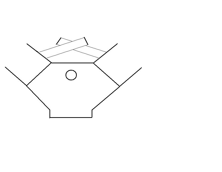
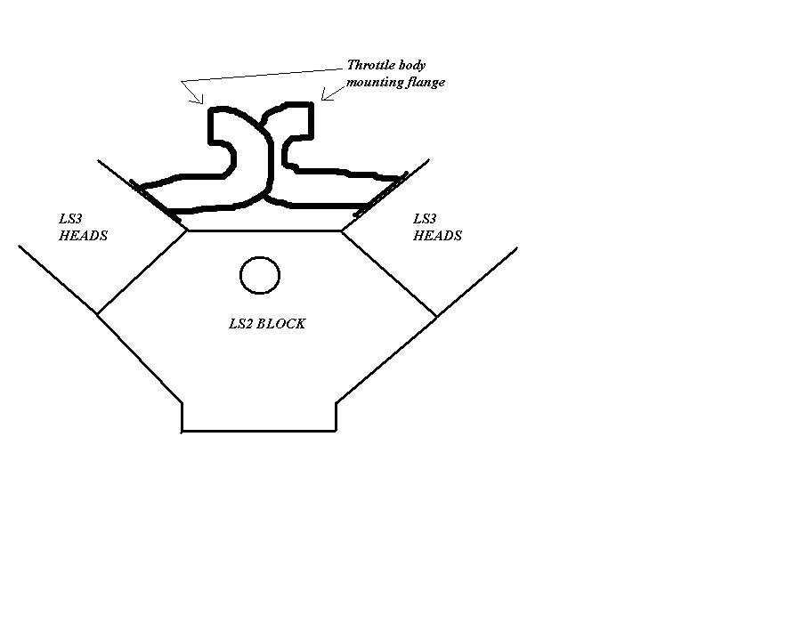
1. To be able to fit in a C5 I know I�ll need to make it a low-profile design. I know the length of the runners play a big part in how the manifold will perform. My question here is: Say my runners will be 8� long. I can either cris-cross them or have them almost cross and then turn away. I drew two pics so you can see what I�m talking about. Please hold the laughs in. LOL!!!! Would curving the runners like in the second pic (curve will not be as sharp as in pic) change the way the manifold will perform even though both designs have 8� runners?
2. Also, the throttle bodies will need to be drive-by-wire just like the LS2 TB. On the LS2 TB the TPS and the TB motor are all built into one. Any ideas on how to work around this except having to go with a throttle linkage cable?
3. What size runners should I use? I�m thinking of measuring the LS3 port opening and using that as my I.D. of the runners I�ll be making.
Any other ideals or comments will be greatly appreciated. Again, this is for fun and experimental purposes.
So, onto my little project. I�m thinking about going with eight 52mm-55mm throttle bodies and the entire manifold (or most of it) will be constructed of aluminum and maybe a little carbon fiber for the air filtration system. Now here is where I need some help�
1. To be able to fit in a C5 I know I�ll need to make it a low-profile design. I know the length of the runners play a big part in how the manifold will perform. My question here is: Say my runners will be 8� long. I can either cris-cross them or have them almost cross and then turn away. I drew two pics so you can see what I�m talking about. Please hold the laughs in. LOL!!!! Would curving the runners like in the second pic (curve will not be as sharp as in pic) change the way the manifold will perform even though both designs have 8� runners?
2. Also, the throttle bodies will need to be drive-by-wire just like the LS2 TB. On the LS2 TB the TPS and the TB motor are all built into one. Any ideas on how to work around this except having to go with a throttle linkage cable?
3. What size runners should I use? I�m thinking of measuring the LS3 port opening and using that as my I.D. of the runners I�ll be making.
Any other ideals or comments will be greatly appreciated. Again, this is for fun and experimental purposes.
well, i think the harrop style is like your first pic, so thats a proven design. The bottom one is similar to like an inglese style, but they point straight up. What youve got there reminds me of the inside of a composite intake, but with shorter runners.
im all for seeing you do it because the only other ones out there are $$$$ because of the crazy fab work the shops put in (either in cf or alum), but i think youd want to straighten them out a lot (compared w the second pic) for the sake of flow (seems like a lot of turbulence building up in those curves with an itb setup -no plenum)
im all for seeing you do it because the only other ones out there are $$$$ because of the crazy fab work the shops put in (either in cf or alum), but i think youd want to straighten them out a lot (compared w the second pic) for the sake of flow (seems like a lot of turbulence building up in those curves with an itb setup -no plenum)
Ya those ITB intakes are pricey and way out of my price range. But I know that a lot of cost has to do with all the design and exotic materials used. I rather put that money into the bottom end where it really needs to be.
Ya that's what I figured on the curved design. I'm just brainstorming here. I like to design as much as I can before I even attempt to cut. As they say....measure twice, cut once.
Thanks for the tip.
Any ideas on what TB would be better to use?
Ya that's what I figured on the curved design. I'm just brainstorming here. I like to design as much as I can before I even attempt to cut. As they say....measure twice, cut once.
Thanks for the tip.
Any ideas on what TB would be better to use?
Last edited by Danny; Apr 18, 2011 at 02:33 PM.

Staging Lane
Joined: Jan 2006
Posts: 69
Likes: 0
From: New York
try looking in the forum at www.gt40s.com
there is a thread started by someone named Terry Oxendale, who built an ITB out of an Edelbrock manifold and some salvaged throttle bodies from a Dodge. Very interesting, cool, and cheap! Should give you some ideas.
there is a thread started by someone named Terry Oxendale, who built an ITB out of an Edelbrock manifold and some salvaged throttle bodies from a Dodge. Very interesting, cool, and cheap! Should give you some ideas.
Ok, here’s something I was thinking about last night. I want to keep the throttle DBW. To do this I was thinking about getting a C5 or a C6 throttle body and removing the motor and shaft from it. (I think a C5 TB can be used with a adapter harness) Then once I have all the throttle bodies linked together I can connect them to a common linkage. Then incorporate the motor/shaft assembly into this common linkage. I can gear the linkage system to open all the TBs close to the same % as the stock LS2 TB would open up.
What do you guys think?
What do you guys think?
Trending Topics
LS1 Tech Stories
The Best V8 Stories One Small Block at Time

6 Common C5 Corvette Failures and What's Involved In Repairing Them
Pouria Savadkouei
Retro Modern Bandit Pontiac Trans AM Comes With Burt Reynolds' Autograph
Verdad Gallardo
Top 10 Greatest Cadillac V Series Performance Models Ever, Ranked
Pouria Savadkouei
Top 10 Most Powerful Chevy Trucks Ever Made!

Hennessey's New Supercharged Silverado ZR2 Has 700 HP
Verdad Gallardo
Coachbuilt N2A Anteros Is an LS2-Powered C6 Corvette In Italian Clothes
Verdad Gallardo
Awesome K5 Blazer Restomod Comes With C7 Corvette Power
Verdad Gallardo
10 Camaros You Should Never Buy

10 LS Engine Myths That Refuse to Die
Verdad Gallardo Ya, the plan that I have is link all the TBs together. Then have a "main linkage" from each bank and connect it to the DBW module.
I'm still have a few designs on the drawing board. I just need to figure out what TBs to use and how to link them together.
I'm still have a few designs on the drawing board. I just need to figure out what TBs to use and how to link them together.

You want the runners to cross like the Harrop's do. You will also want much longer runners than 8" if you are building a street/hydraulic roller engine. IIRC my Harrop runners are ~12" (plus trumpet length or including trumpet length--I'm not remembering right now).
You can do DBW, but that will make life much more difficult for both tuning and fabrication. The Harrop uses a pair of gears to control what would otherwise be controlled by a throttle cable. You will always have to work out the synchronization between the 8 tb linkages no matter if it's dbw, or dbc.
FYI: I'm converting my engine to dbc. I like it better, especially for itb. The throttle response of itb's is just ridiculous and it's easier to modulate the throttle at low speeds with a mechanical linkage than a computer/small electric motor/sensors.
Just throwing that info out there. Good luck with the project, I've contemplated making my own itb's at times too.
Last edited by Stage7; Apr 26, 2011 at 09:04 AM.
So the runners on your Harrop are 12” from the beginning of the runner to the end of the trumpet? Would it make a difference in power if I made 6” runners w/ 6” trumpets VS 10” runners w/ 2” trumpets? The TBs would obviously be closer to the heads on the setup with the 6” runners.
The reason why I want to make is DBW is because the car its going on (C6) is already setup for DBW. I think the way I want to setup the DBW mechanism just might work. As I said before I want to get a factory LS2 TB, break it open and use the motor and shaft. Then incorporate that into the main linkage/actuator. I’ll have it setup so that all the TB blades open up the same amount as the single LS2 would when in use. For example: if the single LS2 90mm TB opens up at 65% under X amount of pedal travel, the TBs on the ITB manifold will open up the same amount with the same amount of pedal travel. This way when I give it, say 50% throttle, the PCM will think it’s only opening up the stock TB when it actually is opening 8 individual TBs. I can make the linkage to each side fully adjustable to fine tune this. Fine tuning each individual TB is another story.
I’m going to take off the manifold off the LS2 this wknd and take some precise measurements. Then build a platform that will replicate the heads on the block. This way I can start building the manifold on this without the need for the block & heads. I’ll be building it first out of softer materials (wood, plastic, etc) to make the designing process easier to work with. Once I have a design that I like I will just copy the design using aluminum and maybe some CF.
So the runners on your Harrop are 12� from the beginning of the runner to the end of the trumpet? Would it make a difference in power if I made 6� runners w/ 6� trumpets VS 10� runners w/ 2� trumpets? The TBs would obviously be closer to the heads on the setup with the 6� runners.
The reason why I want to make is DBW is because the car its going on (C6) is already setup for DBW. I think the way I want to setup the DBW mechanism just might work. As I said before I want to get a factory LS2 TB, break it open and use the motor and shaft. Then incorporate that into the main linkage/actuator. I�ll have it setup so that all the TB blades open up the same amount as the single LS2 would when in use. For example: if the single LS2 90mm TB opens up at 65% under X amount of pedal travel, the TBs on the ITB manifold will open up the same amount with the same amount of pedal travel. This way when I give it, say 50% throttle, the PCM will think it�s only opening up the stock TB when it actually is opening 8 individual TBs. I can make the linkage to each side fully adjustable to fine tune this. Fine tuning each individual TB is another story.
I�m going to take off the manifold off the LS2 this wknd and take some precise measurements. Then build a platform that will replicate the heads on the block. This way I can start building the manifold on this without the need for the block & heads. I�ll be building it first out of softer materials (wood, plastic, etc) to make the designing process easier to work with. Once I have a design that I like I will just copy the design using aluminum and maybe some CF.
You may have a hard time using the Ls2 TB motor. I used a Ls1 throttlebody motor in my c6 with a separate TPS sensor. Ed at Va Speed did the setup when my engine/manifold in it's original config was on their engine dyno, so I would defer to him for exact details as I just continued with how he setup the tb motor/tps. It looked pretty straight forward though.
Your TB motor will not live very long trying to actuate 8 tb's and linkages without a steep gear setup to multiply the torque. This I do know,and have experienced with another itb manifold. You can get it to work, but the motor will burn out. You better hope the fail safe works in the tb motor once it dies.
Launching!
Joined: Feb 2004
Posts: 271
Likes: 0
From: California
Your TB motor will not live very long trying to actuate 8 tb's and linkages without a steep gear setup to multiply the torque. This I do know,and have experienced with another itb manifold. You can get it to work, but the motor will burn out. You better hope the fail safe works in the tb motor once it dies.
I have to double check, but I believe it's 12" including the trumpets. I don't know what making the runners under the throttle blade 6" would do if the overall length including the trumpets was kept at 12".
You may have a hard time using the Ls2 TB motor. I used a Ls1 throttlebody motor in my c6 with a separate TPS sensor. Ed at Va Speed did the setup when my engine/manifold in it's original config was on their engine dyno, so I would defer to him for exact details as I just continued with how he setup the tb motor/tps. It looked pretty straight forward though.
Your TB motor will not live very long trying to actuate 8 tb's and linkages without a steep gear setup to multiply the torque. This I do know,and have experienced with another itb manifold. You can get it to work, but the motor will burn out. You better hope the fail safe works in the tb motor once it dies.
Here's another idea, and again this is just me brainstorming here.... Is it possible to wire two LS1/2 TBs in series so they open up at the same time and work together? The reason why I ask is, instead of using one TB motor I can use two and divide the stress. Then I can also gear the linkage a little steep to alleviate more stress off the motors.
I would really prefer to keep the DBW setup but if it's not going to work or proves to be too complicated/expensive I can always fall back on a DBC setup.
It's more of a personal achievement project than anything else. Also, IMO a poperly setup ITB manifold will outflow any plastic manifold, maybe even the sheet metal manifolds on the market. This manifold will come in handy once I bore/stroke my motor and get better flowing heads. Plus, they just look badass.

Launching!
Joined: Feb 2004
Posts: 271
Likes: 0
From: California
My recommendation would be to stay with a cable setup.
The computer will probably not like you doing this... Due to the safety implications of TBs not working, GM has obviously programmed numerous error checking and fail-safes into the ECU. Any tampering of a TB will require deactivation of these codes. In doing so, you could be risking injury.
My recommendation would be to stay with a cable setup.
My recommendation would be to stay with a cable setup.