Gen4 5.3L Powered Boat
 08-23-2021, 01:10 PM
#21
TECH Addict

 fun stuff, say looking at the pic,, I see your keeping the power steering pump? does your boat use that for steering or for outdrive control?
If it helps ,, there is a version of the pump that doesn't have the tank attached to the pump (Remote tank instead) Just in case it gets tight on clearance for the plumbing.
Since the exhaust housing is water cooled, could you make a bracket to mount the coils there? so stock style wires reach? (Curiosity from the peanut gallery... )
 08-23-2021, 03:10 PM
#22


“fun stuff, say looking at the pic,, I see your keeping the power steering pump? does your boat use that for steering or for outdrive control?”
the power steering pump fits into the hydraulic power steering ram on bravo outdrives. It works something like a regular (feedback) steering cable from the helm to the hydraulic actuator that then functions like a rack and pinion steering system. It pushes a little tiller back and forth to steer outdrive. I could’ve deleted it but I thought I was asking for issues driving a 450hp boat with non-power steering…
I think I’ll have room for everything. I have a LOT of space since the boat originally came with twin 351W’s for a total of 500hp. One of my goals is to keep the stock serpentine belt and marinize the LS as much as I can. I may have to revisit your idea, thanks for it, I’ll keep it in mind.
im not really sure on the coils. I’ve looked at it so much I’m going cross-eyed. I toyed with rigging up somethign off the exhaust manifold bolts. The biggest problem is where to relocate the coils. I wanted to put them below on the block but I’m running out of holes. I could rig up a bracket thingy. I could mount them on the transom or another point but for time and simplicity I think that’s the quickest way. It’s a dance for me between time and money. Can I? Sure. Will I be able to make anything better for less $$ in HI? Doubtful… for $150 that just may solve all my issues.
right now the mission is get the engine done, running, tuned. I’ll install using a chain hoist and a gantry crane I made. Then The gimbal housing and outdrive will be next.
as to the engine. It will have closed cooling. I’ve almost got all the cooling system parts sorted out for it. The harness wiring should begin this week.
my system follows same routing as pic below but I found a way to crank mount the raw water pump like ilmor does in their marine LS engines. But this is what I’m aiming at.

https://i.postimg.cc/T1xnmyg6/LS_Cooling1.jpg
https://i.postimg.cc/RFKcN13d/LS_Cooling.jpg
Last edited by xcomunic8d; 08-23-2021 at 03:34 PM.
09-04-2021, 08:30 PM
#23
So it’s been awhile since I’ve updated this. I’ve been having a terrible time getting stuff. My wife’s school (and where our kids go) went to distance learning for 2 weeks. There have been a few cases across the campus and they had no choice. My son tested positive. He’s doing ok so far.
So I had ordered a matching gen 4 harness and pcm. That’s not gonna work. So I ordered a stand-alone LS1 harness that was labeled dbc. But it’s a dbw. So I ordered another harness and the correct 12200411 pcm and sent it to Brendan at lt1swap.com for programming.
Here I’ve been able to get the balancer back on. I had to order a 1157-0163 ls7 ($20 Chevy dealer) crank bolt and used about 8-10 1/2” washers to push that thing on. You’ll need someone with a breaker bar on the flywheel.
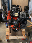
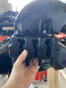
My plan for the coils won’t work either so I’m thinking of fabbing a bracket to go here or just screw them to transom. Thoughts? I’m making custom plug wires via a msd kit.
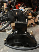
And here is what the raw water pump looks like when it is bolted down via bracket and crank bolt connector through marine engine depot.com
Well now I’m stuck at home for another 9 days until we all get tested. Eagerly awaiting the harness and parts. Guess I’ll do some glass work and painting as weather permits.
So I had ordered a matching gen 4 harness and pcm. That’s not gonna work. So I ordered a stand-alone LS1 harness that was labeled dbc. But it’s a dbw. So I ordered another harness and the correct 12200411 pcm and sent it to Brendan at lt1swap.com for programming.
Here I’ve been able to get the balancer back on. I had to order a 1157-0163 ls7 ($20 Chevy dealer) crank bolt and used about 8-10 1/2” washers to push that thing on. You’ll need someone with a breaker bar on the flywheel.
My plan for the coils won’t work either so I’m thinking of fabbing a bracket to go here or just screw them to transom. Thoughts? I’m making custom plug wires via a msd kit.
And here is what the raw water pump looks like when it is bolted down via bracket and crank bolt connector through marine engine depot.com
Well now I’m stuck at home for another 9 days until we all get tested. Eagerly awaiting the harness and parts. Guess I’ll do some glass work and painting as weather permits.
 07-29-2022, 12:18 AM
#25
wow I�m way behind on here. I have another build thread going on classicseacraft.
Here�s some reposts. Basically been lots of twice is nice stuff.
EDIT: a plate to plate will not work. Much, much more cooling required. Do NOT attemptI worked with Brandon at mrcool
heres an email of my research to find a marine heat exchanger that would work with the Ls:
Per our conversation on LS swap boats. I�ve found that crusader (also pleasure craft marine I believe they are under the same parent company) use a LS based engine in some instances (6.0). I know Ilmor and I believe Indmar utilize the LS. However, I�m excluding them for this conversation. My preliminary research shows crusader is the least expensive and most readily available.
I prefer Crusader due to the full closed cooling design. The Hardin Marine setup only does half closed (block only not exhaust) and costs $1600. https://www.hardin-marine.com/p-7409...per-brass.aspx
Below is a picture of the crusader 6.0.
[img]blob:https://ls1tech.com/de5cade3-1474-4331-82db-65e1b32ece8f[/img]
Here is a link to the Crusader parts manual. Throughout the drawings reflect LS architecture.
Please see:
pic on p1
Pic on p8 of water pump diagram
Pgs 32-41 diagram the closed cooling and detail the setup for the 6.0
https://www.crusaderengines.com/wp-c...03/L510018.pdf
Here�s another view of the cooling diagram
https://macombmarineparts.com/pages/...tem-components
Parts required:
Heat exchanger- RA0147048a
Marine parts.us:
Heat exchanger Thermostat housing and splitter - r025038- $65.35
Perf protech:
Heat Exchanger Bracket- r090258- $137.15
Degas bottle- r146001-$75.38
Degas cap- r034045- $23.36
Degas bottle bracket?
Various suppliers:
Water pump inlet and threaded port- R025036 $44.27 p8 of crusader diagram
Searching for:
Water pump tee- R025035a
i used this:
https://www.hardin-marine.com/p-1004...-1-14-tee.aspx
Misc hoses and clamps.
Per our first call, I learned that 1hp =2,500 BTU�s. However that number does not include the cooling requirements of a full closed system. Maybe you can back into it from the information provided.
Closing notes in exhaust manifolds. I bought these from Hardin Marine https://www.hardin-marine.com/p-1045...-53-60-62.aspx
I wanted to keep iron out of the boat in my salt water environment. However, I did not consider that I might need exhaust riser spacers. I am now faced with definitely needing spacers and will probably have to fabricate them myself. I would tell others to buy the crusader or pcm exhaust elbows and risers if they might need spacers. Perforate h has a good article about this
07-31-2022, 01:25 PM
#26
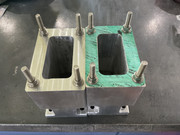
We are in process of making spacer blocks. It’s important that the exhaust be above the water line and it would not be at its natural angle.
spacers don’t exist for this ser of manifolds
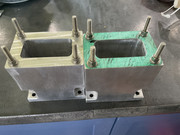
so… I bought a block of 4”x6”s12” 6061 aluminum stock.
cut it in 2 to end up with 2 nearly 6” spacers.
Due to how the coolant stays in lower part (elbows) and raw water exits out the top (risers). We simply milled a center hole for the exhaust to match and cut non threaded through holes on bottom set and threaded holes on top side of this spacer block. It’s hit some delays as my machinist has had heart problems and been in hospital and had surgery. More to come when I can.
spacers don’t exist for this ser of manifolds
so… I bought a block of 4”x6”s12” 6061 aluminum stock.
cut it in 2 to end up with 2 nearly 6” spacers.
Due to how the coolant stays in lower part (elbows) and raw water exits out the top (risers). We simply milled a center hole for the exhaust to match and cut non threaded through holes on bottom set and threaded holes on top side of this spacer block. It’s hit some delays as my machinist has had heart problems and been in hospital and had surgery. More to come when I can.
 08-08-2022, 12:01 AM
#28
TECH Addict
If you run in to issues with the water pump, have you looked at the water pump for a sprint car?
Some are crank mounted and they push enough water for 800HP + (Just a plan C.. )
Some are crank mounted and they push enough water for 800HP + (Just a plan C..
)
08-08-2022, 02:22 AM
#29


Keep in mind sprint don't need much flow if they are running methanol, Hell sometimes it hard to just get heat in them before the green flag drops.
08-08-2022, 02:53 AM
#30
the problem was the heat exchanger (water cooled radiator). A plate to plate did not have enough capacity. I ended up with a monster one.
2nd pump is for raw water to circulate from outside boat into heat exchangers (coolers for antifreeze, oil. And power steering). I have that crank thing that crusader/pleasurecraft/ilmor run. I’ll keep your suggestion in mind.
Once I get these spacers painted I should be able to put engine back together.
wire up gauges and bleed and double check systems.
I hope to start it soon
then rebuild my bravo 3… another 4K… then do the trailer. It’s only money n
 10-31-2022, 02:34 AM
#32
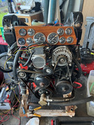
And it runs. This is it idling. I’ve been bringing it up to temp and cycling it. Run it for a few minutes up to temp and off. It’s got about 20mins run time. I’m about to change the oil out and run up the rpm’s. A conventional 5w30. Think I’ll leave the magnetic drain plug in for now. Or maybe put a strong magnet on the oil filter and swap over to my lever drain plug thing with a hose adapter. Used in boats for oil changes.
the trg-002 is working fine. The stand-alone harness is working well. I did convert the ev1 to ev6 by cutting and splicing in new ones. Think there’s a slight vacuum leak around the throttle body. I haven’t had time to figure it out yet.
I have some significant work to get done before I can install it in the boat but this part is done.
like I have to cut the keyhole and install transom assembly that functions as the rear motor mount.
08-28-2023, 01:59 AM
#34
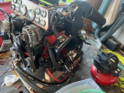
The engine build side is done. Now I need to drop it in. Events, life, work have been really crazy here (read no time or money).
im fabricating the motor mounts and trying to figure out how to store it to keep rain off of it as the rainy season will start any day and it’s been rainy here all summer. The gimbal housing is in (that also doubles as the rear motor mount. Now I need to string line layout and fab the motor box for the engine and I hopefully can drop in.
I’ve been doing wiring and stuff as I can but I need to get this done…