


Won't start
Nope, no alterations, that's just all I have handy. I dunno if this is useful, but apparently the dealer had already replaced the transmission a few years ago, and the owner said one of his kids got some change stuck in the cd slot not long before he brought it to me, but he pulled the radio and got it out.
TECH Enthusiast
Joined: Nov 2008
Posts: 622
Likes: 1
Now here is something I forgot about a lot of 07`s had a problem as inside the trans the harness was improperly installed and failed.
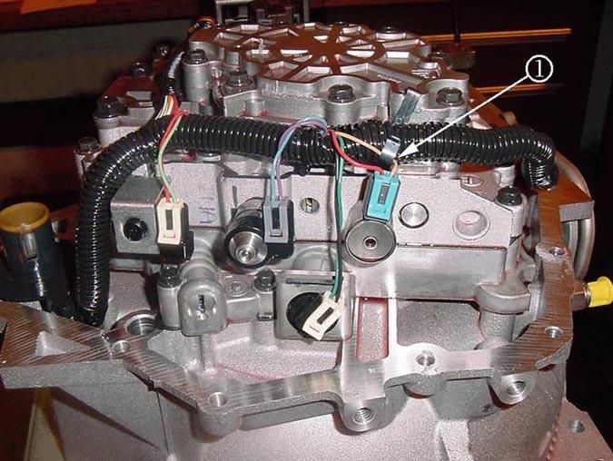
This you can test for at the trans (trans side) 20 pin connector check it for a short ( new diag to follow) looks like pin T, trans side

This you can test for at the trans (trans side) 20 pin connector check it for a short ( new diag to follow) looks like pin T, trans side
Last edited by Ill_Born_ss; Feb 20, 2014 at 02:18 PM.
TECH Enthusiast
Joined: Nov 2008
Posts: 622
Likes: 1

reference Basic Temperature 68* / 190*
A-E 1-2 Shift Solenoid 19-24 / 24-31
B-E 2-3 Shift Solenoid 19-24 / 24-31
T-E TCC/PWM Solenoid 10-12 / 13-15 ALL measured in ohms
C-D EPC Solenoid 3-5 / 5-6
S-V Input Speed Sensor 893-1127 / 1132-1428
M-L TFT Sensor 3164-3867 / 225-285
Output Speed Sensor 981-1864
Internal mode switch if you are not sure how to check it let me know!
I would check all the internals first and get rid of the possibility inside it.
Last edited by Ill_Born_ss; Feb 21, 2014 at 10:27 AM.
Is that all expected resistance on those circuits?
And that internal mode switch is a mess, I'm assuming it grounds a combination of those circuits based on gear shift position.
And that internal mode switch is a mess, I'm assuming it grounds a combination of those circuits based on gear shift position.
Last edited by spy2520; Feb 20, 2014 at 08:02 PM.
LS1 Tech Stories
The Best V8 Stories One Small Block at Time

Gas Monkey Built a 6-Wheel Ferrari Testarossa With a Corvette LT4 Engine
Verdad Gallardo
7 Most Reliable High-Performance Engines GM Has Ever Built
Verdad Gallardo
Amazing '71 Camaro Restomod Is Modern Muscle Car Under the Skin
Verdad Gallardo
6 Common C5 Corvette Failures and What's Involved In Repairing Them
Pouria Savadkouei
Retro Modern Bandit Pontiac Trans AM Comes With Burt Reynolds' Autograph
Verdad Gallardo
Top 10 Greatest Cadillac V Series Performance Models Ever, Ranked
Pouria Savadkouei
Top 10 Most Powerful Chevy Trucks Ever Made!

Hennessey's New Supercharged Silverado ZR2 Has 700 HP
Verdad Gallardo
Coachbuilt N2A Anteros Is an LS2-Powered C6 Corvette In Italian Clothes
Verdad GallardoTECH Enthusiast
Joined: Nov 2008
Posts: 622
Likes: 1
Yes... low temp and high temp values
if your meter has beep just attach the black to pin K and the switch in the diag is already in P so K- W,J,F,G will beep
move the gearshift to each detent selector and check each
R- K- F,G
N-K-W,J,G
D-K-H,G
3-K-H,F,J,G
2-K-H,F
1-K-H,J
if your meter has beep just attach the black to pin K and the switch in the diag is already in P so K- W,J,F,G will beep
move the gearshift to each detent selector and check each
R- K- F,G
N-K-W,J,G
D-K-H,G
3-K-H,F,J,G
2-K-H,F
1-K-H,J
Last edited by Ill_Born_ss; Feb 21, 2014 at 10:19 AM.
Here are my findings:
A-E ~ 20 ohms (expected 19-24 / 24-31)
B-E ~ 20 ohms (19-24 / 24-31)
T-E ~ 10 ohms (10-12 / 13-15)
C-D ~ 4 ohms (3-5 / 5-6)
S-V ~ 865 ohms (893-1127 / 1132-1428)
M-L ~ 6480 ohms (3164-3867 / 225-285)
VSS ~ 1867 ohms (981-1864)
It is way colder than 68* here and I tested these at the TCM connector (except pin W) so i expected some deviation from spec
Now for the Mode switch, everything seemed correct except in park I got an open circuit on G-K. For comparison I tested the old transmission, and its exactly the same. So on both transmissions i got all of the same results in each gear including nothing on G-K. Leads me to believe the trans internals are ok. What do you think?
edit: also just for *****, i got 0 ohms when measuring pin 49 at the tcm connector to the case of the transmission, leading me to believe the grounds are ok.
Last edited by spy2520; Feb 21, 2014 at 08:41 PM.
Yes G-K worked for reverse, neutral, drive, and 3.
Pin W does go to the ECM, i pulled the connector on the trans to check that as it was the only pin i could actually see. And W-K worked on park and neutral.
I checked pin 49 at the TCM connector (pin K at trans) to the transmission case ( G111 attaches right below the starter) and got 0 ohms, so i assume it is good.
edit: i say pin but the TCM connector is female, you know what i mean.
What's the best way to go about doing that? And in theory, would disconnecting the battery, getting the trans in neutral and connecting everything back up allow it to start? If the mode switch is the problem.
TECH Enthusiast
Joined: Nov 2008
Posts: 622
Likes: 1
You may be able to just get to the pin 46 side of it at the TCM (yellow wire) and jump it to a ground or take 2 needles/pins and poke them thru each of the yellow G and the blk/wht K wires by the 20 pin conn and jumper the 2 needles/pins.
No the IMS has to send all triggers to the computers if 1 is missing the sentence it is sending makes no sense.
ALSO can you test each of L,M,D,C,E,B,A,T,V,S to the case for resistance all should be greater than 250ohms
Also test G-K again on both trannies and try to apply a little pressure/turning to the shaft and see if with just a little persuasion the G-K connection can be made ( must be with very little effort)
Be patient as we must find the problem and also what caused it (thinking shift cable adjustment)
Last edited by Ill_Born_ss; Feb 22, 2014 at 05:50 PM.
I'm leaning towards a possible VTD issue. I can't find a problem with the trans. There must be something stopping the ECM from working, I remember the CAN high speed + and - terminals giving strange high resistance with the key on.
I don't know where else to look, Or how to go about checking the VTD though.
edit: maybe not considering the security light is behaving as normal....
I don't know where else to look, Or how to go about checking the VTD though.
edit: maybe not considering the security light is behaving as normal....
Last edited by spy2520; Feb 26, 2014 at 09:38 PM.
TECH Enthusiast
Joined: Nov 2008
Posts: 622
Likes: 1
Those 4 signal wires from the TCM to the trans put out voltage, when the switches are made they drop that voltage from high to low and in turn the TCM sends power to the ECM.This does not include what the neutral safety switch is doing. So as an example if 1of the four switches is not being made during park for example then the TCM only sees HI< LOW<LOW<LOW when it is supposed to see LOW<LOW<LOW<LOW It is really hard to relay what happens and when as the system is really designed to be tested with the tech2 which is sometimes hard by itself, so testing the way we are is somewhat difficult.
The VTD system is a possibility, do you get the dash test when you first turn the key? do you see the security light on the dash during the one click and the 2 click use of the remote? Do you get the beep/ 2 beeps of the horn with each of the remote functions? If you use the remote with one click does the light come on and stay on for 30 seconds then go out? Have you tested the ignition /start as in the diagram above to see if the ignition switch is doing its part and power is actually getting to and then passing thru to its first power out for the start.
You did mention about the BCM and the radio and the no gear position, obviously someone was in there maybe trouble at splice 207 or a loose connector on the radio as the data lines go there too and to the DIC and to the VDT and the ignition transponder reader. If for example someone pull hard on a harness to remove something it could of pull pins or cut a wire on a member/support.
Last edited by Ill_Born_ss; Feb 27, 2014 at 09:46 AM.
Those 4 signal wires from the TCM to the trans put out voltage, when the switches are made they drop that voltage from high to low and in turn the TCM sends power to the ECM.This does not include what the neutral safety switch is doing. So as an example if 1of the four switches is not being made during park for example then the TCM only sees HI< LOW<LOW<LOW when it is supposed to see LOW<LOW<LOW<LOW It is really hard to relay what happens and when as the system is really designed to be tested with the tech2 which is sometimes hard by itself, so testing the way we are is somewhat difficult.
The VTD system is a possibility, do you get the dash test when you first turn the key? do you see the security light on the dash during the one click and the 2 click use of the remote? Do you get the beep/ 2 beeps of the horn with each of the remote functions? If you use the remote with one click does the light come on and stay on for 30 seconds then go out?
You did mention about the BCM and the radio and the no gear position, obviously someone was in there maybe trouble at splice 207 or a loose connector on the radio as the data lines go there too and to the DIC and to the VDT and the ignition transponder reader. If for example someone pull hard on a harness to remove something it could of pull pins or cut a wire on a member/support.
And if the car is in neutral when the battery is connected, shouldn't the car Tcm and ecm see the correct values from all 4 switches? Keep in mind both transmissions responded the same way leading me to believe there may have been a change to the G circuit in Park.