When you click on links to various merchants on this site and make a purchase, this can result in this site earning a commission. Affiliate programs and affiliations include, but are not limited to, the eBay Partner Network.
Getting a new thread going from the speedmaster thread since that project is going to be on hold for a bit, hoping superglide can successfully pull that one off with his buddy as I don't have the resources to port match my heads right now. If you don't know already I decided to go the LS2 intake manifold route due to ease of install and out of all the intake manifolds is the best performer once it is ported, that being said I ordered one from Complete Street Performance and am currently waiting to get that in so I can post up some pictures, but this will serve as the build thread for this project. Here is a full list of what it will consist of with part #'s and items required, along with some pics.
REQUIRED
2005-2007 Chevrolet Corvette
2005-2006 Chevrolet SSR
2006–2009 Chevrolet TrailBlazer SS
2006–2007 Cadillac CTS V-Series
2005–2006 Pontiac GTO
LS3 90mm Gold Blade Throttle Body (LS2 also works fine) PN ACDelco 217-3153
Type 18-8 Stainless Steel Flat-Head Socket Cap Screw M8 Size, 30mm Length, 1.25mm Pitch - McMasterCarr 92125A290 (Optional to the Included Hardware with the ICT Billet Valley Cover for more secure mounting, included bolts on mine were very short)
Type 18-8 Stainless Steel Socket Head Cap Screw M6 Thread, 110mm Length, 1mm Pitch - McMasterCarr 91292A420 (Optional Intake Manifold Bolt Replacements)
Important Note: Your car may fail to start upon initial start without help from the gas pedal, based on testing with superglides car, the LS7 maf requires a significant amount more fuel over the stock MAF table, you may have to raise the MAF table by up to +20% or more to get the car to run smoothly enough to maintain idle.
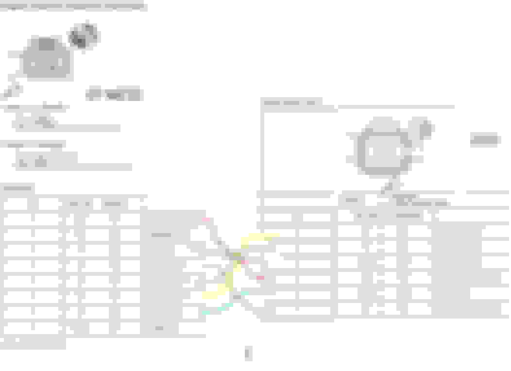
The LS7 MAF Sensor with the included IAT sensor uses different resistance values compared to the stock LS4 MAF and IAT, these value changes need to be brought over from the LS7 tune file in HPTuners to your LS4 tune file, copying the resistance values axis and editing them to match in the LS4 tune file is required. Example below.
The differences in the MAF scale with the LS7 sensor and the lack of an ability to tune VE on the E67 ecu causes the P0101 code to be set upon startup as the predicted MAF values do not match the actual values. P0101 testing must be disabled on startup. Change the values to match the picture below.
Notes about P0101 Diagnostics:
A low minimum air rate through the sensor bore may cause this DTC to set at idle or during deceleration. Inspect for any vacuum leaks downstream of the MAF sensor.
The barometric pressure (BARO) that is used in order to calculate the predicted MAF value is initially based on the MAP sensor at key ON.
The LS4 ecu must also be told that there has been a change in throttle body diameter to allow for proper idle airflow, ETC Area Scalar must be changed to match below.
CONNECTOR PINOUT CHANGES (pulled from the sticky)
SEE PAGES 2-4 FOR DETAILS REGARDING DTC's P2101 and P1516
You can run 5v ref and low ref from either TPS1 or TPS2 for the 8pin to 6 pin conversion. I personally recommend leaving the 5v ref and low ref from TPS2 disconnected and use only TPS1 signals. The red and blue squares indicate the circuits which are tied together.
The magnum valley cover gasket is designed to fit the oem DOD tray, so it has push pins to snap it in place that need to be removed, the top of the gasket must be flush with the ICT billet valley tray. Additionally, there are oil passages that allow oil to flow through the center posts in the valley to the DOD solenoids, these passages need to be blocked off, JBweld or marinetex works well for this. You may modify the gasket how you see fit, but remember the purpose of using this gasket, is to be able to provide a seal around the DOD oil passages in the center of the valley, without them oil pressure is lost through these as it sprays out and bounces against the bottom of the ICT valley cover. Traditional GM covers used on other Gen4 blocks have o-rings embossed into the cover itself. As show here http://www.briantooleyracing.com/6-2...-12598832.html the 6.2 valley cover is optional to use in place of the ICT valley cover and this particular gasket, however the OPSU port would have to be modified to face 90 degrees out the side vs completely vertical. PN of the 6.2 valley cover is 12598832
The ICT Billet valley cover comes with install hardware, however what was included with my kit was far too short to be used safely without running the risk of damaging the threads when torqued. Here you can see the difference between what was included, the updated hardware listed in the parts list, and the OEM valley tray bolts.
In order to raise the OEM fuel rail to the required height to clear the LS2 manifolds larger runners, injector spacers must be used. Two types are available, bottom mount FAST injector spacers, and top mount hats from FIC (fuel injector connection) the FAST spacers do not interrupt the injector spray pattern despite being bottom mounted as our particular style injector is a needle point spray pattern with a maximum of 10*arc at 6", it is designed to fire directly at the back face of the intake valve. They are also significantly cheaper then the FIC top mount hats.
Intake tube sizing is optional but it is recommended that you run at least 3.5", for this install im running a 4" intake which is paired directly with the size of the throttle body mounting. 45 degree bend is required for any setup. Due to the small length of the LS4 intake, it is recommended to run a honeycomb in front of the MAF sensor to help improve airflow over the MAF and reduce turbulence coming in from the filter. Pics coming soon.
more deets coming soon as the rest of the parts arrive and I begin the install.
Last edited by spawne32; May 11, 2016 at 10:11 PM.
Nice! Just waiting on the intake or have to order the rest as well?
Mostly just the intake, the maf honeycomb is on order, and i have a few parts arriving between tomorrow and wed. I just hope we arent going back and forth between warm weather and snow like we have been for the past week here when I get everything in and ready.
You can use the bluecat program to tune VE on the E67... That's what I did for my setup.
If you find a complete top end take off (LS2 Throttle body, Intake, Fuel Rail, & Injectors) you might want to use the LS2 injectors vs. LS4 ones. LS2 injectors are taller, flow more, and have the right electrical connector fitting, so then you just need the 4 fuel rail mounting spacers and longer bolts to use the LS4 fuel rail (or bend the fuel rail connector end on the LS2 fuel rail to point in the right direction and use it w/o needing anything).
Could you post up some more deets on the bluecat program?
You're not going to want to run that metal MAF housing. That's one of the big reasons I relocated my IAT sensor because that tube gets too hot to the touch and your IATs will read sky high.
You're not going to want to run that metal MAF housing. That's one of the big reasons I relocated my IAT sensor because that tube gets too hot to the touch and your IATs will read sky high.
The MAF sensor tube is going to be half way into the airbox, ill check it but with the MAF isolated from the metal via the plastic mount and gasket, its free floating in the tube, shouldnt effect the IAT's at all. If anything it should be realistic to how hot the intake air is given how close to the filter it is.
You don't need blue cat anymore the new hp tuners already has it built in
That's cool. I haven't needed to do anything tune-wise to my car in close to 2 years, so I haven't been paying attention to the available updates. Maybe sometime this summer I will update and do some review of my tune.
heres a pic of the back plugs capped off, used my bore scope to verify that they werent at risk of falling into the manifold. Threads were sealed with RTV to keep them in place.
Drilled the map sensor hole out to mount the OEM sensor. I may opt for a slightly thicker gasket here since it wiggles alot not being screwed in.
Installed and lubed up the fast injector hats, parknoob will try to tell you that these will obstruct flow, but like i already said we have pencil point spray pattern injectors, and as an added bonus, the tips of our injectors get seated down into the bottom of these spacers, so they are almost completely flush at the end of the spacer.
heres a nice shot of the new valley tray gasket that goes with the ICT billet tray, and the tray fully installed and torqued down with the katech adapter.
had to call it quits tonight, ran out of sunlight but ill be wrapping this up tomorrow and then tuning it in. I may or may not have to use my modified power steering pump to get this thing all the seated in the valley, going to try rerouting the harness tomorrow and see if it gives me the extra 1/4" i need to get it lined up properly.
All you need to do is shift the harness,no reason to use a modified pumore for a ls2. Also you should take the time now to put some heat reflective material on the bottom of the intake before slapping it on it helps tons. And if you can go around the outer shell with a welder or soldering iron and join the seem it will help with the inherent flaws of the ls2 structure
Gas Monkey Built a 6-Wheel Ferrari Testarossa With a Corvette LT4 Engine
Slideshow: The controversial Ferrari F6 swaps its original flat-12 for a Corvette Z06-derived LT4 V8 and sends power to four rear wheels through a custom-built drivetrain.
7 Most Reliable High-Performance Engines GM Has Ever Built
Slideshow:These GM engines didn't just make huge power, they survived abuse, boost, track days, and six-digit mileage with a reputation for refusing to quit.
6 Common C5 Corvette Failures and What's Involved In Repairing Them
Slideshow: From wobbling harmonic balancers to failed EBCMs, these are the issues that define long-term C5 ownership and what repairs typically involve.
Retro Modern Bandit Pontiac Trans AM Comes With Burt Reynolds' Autograph
Slideshow: A modern Camaro transformed into a retro icon, this limited-run "Bandit" build blends nostalgia with brute force in a way few revivals manage.
Top 10 Greatest Cadillac V Series Performance Models Ever, Ranked
Slideshow: Cadillac didn't just crash the high-performance luxury vehicle party, it showed up loud, supercharged, and occasionally a little unhinged...
Coachbuilt N2A Anteros Is an LS2-Powered C6 Corvette In Italian Clothes
Slideshow: A one-off sports car that looks like a vintage Italian exotic-but hides a C6 Corvette underneath-just sold for the price of a new mid-engine Corvette.