








2 bolt Corvette motor?

TECH Enthusiast

Joined: Feb 2005
Posts: 633
Likes: 4
From: Phoenix, AZ

 j/k
j/kLike Tom stated, nothing wrong with a 2 bolt. I would not worry about it. PLenty of guys putting down serious numbers on a 2 bolt. Being that you are removing heads anyways find some good aluminum ones and slap em on.

Thread Starter
Teching In
Joined: Nov 2009
Posts: 27
Likes: 0
From: Seattle, WA
Excellent...thanks for the info guys. Never got around to getting the pic of the VIN, but I'll grab it sometime soon. Sadly, I'm off tomorrow morning for TX for Christmas, so the project will be on hold for a week or so.
I'm already looking at the LE2 package; thanks for the tip!
I'm already looking at the LE2 package; thanks for the tip!
Thread Starter
Teching In
Joined: Nov 2009
Posts: 27
Likes: 0
From: Seattle, WA
1SR752655 is off the driver side of the tranny
10125327 is off the passenger side of the engine just forward of the bellhousing...I think the second is the casting number. The first doesn't look like any GM VIN I've ever seen, but I certainly haven't seen them all.
10125327 is off the passenger side of the engine just forward of the bellhousing...I think the second is the casting number. The first doesn't look like any GM VIN I've ever seen, but I certainly haven't seen them all.
It's the last 9 digits if I'm correct.....in that case it would make it a 95 block. It however does not indicate what car it came out of. But if that came off the trans, then this is all out the window. The vin # will be stamped into the block somewhere and not cast. I'll have to look at the block in my garage and figure out where exactly it is.
Thread Starter
Teching In
Joined: Nov 2009
Posts: 27
Likes: 0
From: Seattle, WA
Hey all, it's been awhile. I'm making some good progress, and am getting more and more excited about it now that the cleaning is done. HOWEVER, I've run into a problem.
As I said, I'm doing top end only, and leaving the bottom end alone. I've reinstalled everything on the front of the engine, and got the passenger side head installed and torqued tonight. Details.
The problem is, I found THIS on the floor of the basement tonight:

I think it's the ball bearing that is installed into the left rear mains seal prior to the cap installation; it must have shaken out somehow during the rebuild.
I tried reinstalling it through the hole in the cap, which is curved, and it eventually popped out through the oil filter assembly. It's either the wrong hole (hah), or it won't lodge into the right tapered slot.
What do I do? Any other thoughts on where it goes? Can I just pull the rear main cap, install the ball bearing, and reinstall the cap? What affect does that have on the rest of the crank bearings, etc?
Please tell me this isn't going to mean pulling the crank out!!!!!!
As I said, I'm doing top end only, and leaving the bottom end alone. I've reinstalled everything on the front of the engine, and got the passenger side head installed and torqued tonight. Details.
The problem is, I found THIS on the floor of the basement tonight:
I think it's the ball bearing that is installed into the left rear mains seal prior to the cap installation; it must have shaken out somehow during the rebuild.
I tried reinstalling it through the hole in the cap, which is curved, and it eventually popped out through the oil filter assembly. It's either the wrong hole (hah), or it won't lodge into the right tapered slot.
What do I do? Any other thoughts on where it goes? Can I just pull the rear main cap, install the ball bearing, and reinstall the cap? What affect does that have on the rest of the crank bearings, etc?
Please tell me this isn't going to mean pulling the crank out!!!!!!
Last edited by msbuckner97; Aug 9, 2010 at 01:52 PM.
I dont see how it would fall out seeing it is pressed in.
If thats the ball that goes in the rear main oil gallery, it should be .473". At the rear cap mounting area, there are four holes - two for cap bolts and two for oil passages... The ball is located inside the forward most hole on the driver side of the block. I don't remember a hole in the cap, but I don't see what it would hurt to remove the cap, tap in the ball, and torque the cap back down if you needed to.
Hope this helps...
If thats the ball that goes in the rear main oil gallery, it should be .473". At the rear cap mounting area, there are four holes - two for cap bolts and two for oil passages... The ball is located inside the forward most hole on the driver side of the block. I don't remember a hole in the cap, but I don't see what it would hurt to remove the cap, tap in the ball, and torque the cap back down if you needed to.
Hope this helps...
LS1 Tech Stories
The Best V8 Stories One Small Block at Time

Gas Monkey Built a 6-Wheel Ferrari Testarossa With a Corvette LT4 Engine
Verdad Gallardo
7 Most Reliable High-Performance Engines GM Has Ever Built
Verdad Gallardo
Amazing '71 Camaro Restomod Is Modern Muscle Car Under the Skin
Verdad Gallardo
6 Common C5 Corvette Failures and What's Involved In Repairing Them
Pouria Savadkouei
Retro Modern Bandit Pontiac Trans AM Comes With Burt Reynolds' Autograph
Verdad Gallardo
Top 10 Greatest Cadillac V Series Performance Models Ever, Ranked
Pouria Savadkouei
Top 10 Most Powerful Chevy Trucks Ever Made!

Hennessey's New Supercharged Silverado ZR2 Has 700 HP
Verdad Gallardo
Coachbuilt N2A Anteros Is an LS2-Powered C6 Corvette In Italian Clothes
Verdad Gallardo Thread Starter
Teching In
Joined: Nov 2009
Posts: 27
Likes: 0
From: Seattle, WA
I'll check the size tonight; any idea where ELSE it might have come from? It seemed pretty bizarre to me, but what else could it be? I don't think I've got a buckshot round laying open down there anywhere 
Here's the hole in the rear cap I was talking about:
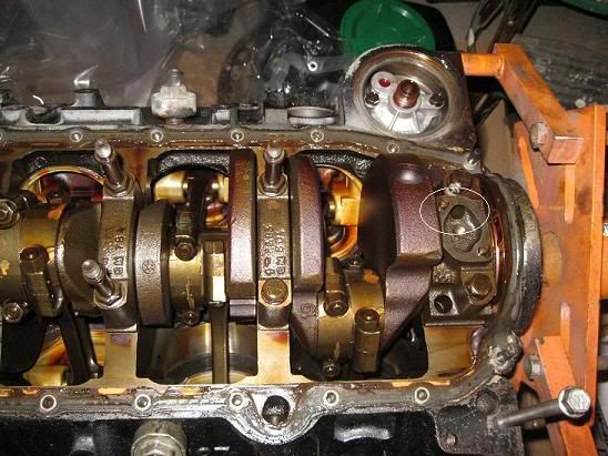
it curves around through the cap, and ends up by the oil filter assembly. Probably oil pump related? If I remember right, the ball bearing just blocks off one passage that was used to create and intersection of two other passages, right? Is that ball visible with a flashlight if it's already installed (if I pull the cap off)?
I'll do a little bit of reading on the main caps, and what it would take to pull the rear one off.
And thanks, Tomos!
Here's the hole in the rear cap I was talking about:
it curves around through the cap, and ends up by the oil filter assembly. Probably oil pump related? If I remember right, the ball bearing just blocks off one passage that was used to create and intersection of two other passages, right? Is that ball visible with a flashlight if it's already installed (if I pull the cap off)?
I'll do a little bit of reading on the main caps, and what it would take to pull the rear one off.
And thanks, Tomos!

Teching In
Joined: Aug 2010
Posts: 3
Likes: 0
Being your running this in an S-10, Current Performance Wiring makes plug and play harnesses for this conversion. Check out the site. They can even make it work with air and factory S-10 gauges and tach. Depends on the year.
Rob
Rob
I dont think you would be able to get the ball in through that hole. It sits in tight and must be tapped in/out with a hammer and some kind of punch. If you take the cap off, the hole should be directly in front of the cap bolt hole on that side. And youre right its used to block off that part of the gallery that was drilled in order to intersect two passages.
If you took the cap off I think you would be able to see it with a flashlight... the ball is to be removed from the top gallery where the oil press sensor mounts so if you cant see it then you could always stick something in there through top or bottom.
If you took the cap off I think you would be able to see it with a flashlight... the ball is to be removed from the top gallery where the oil press sensor mounts so if you cant see it then you could always stick something in there through top or bottom.
Thread Starter
Teching In
Joined: Nov 2009
Posts: 27
Likes: 0
From: Seattle, WA
RCP--someone already turned me onto CPW; I'll be talking to them soon.
Spiers: Thanks much. I'll try to take a look tonight or tomorrow night; I'll let you know how it turns out. I hope it's as easy as pulling the cap, tapping it in, and retorquing.
Spiers: Thanks much. I'll try to take a look tonight or tomorrow night; I'll let you know how it turns out. I hope it's as easy as pulling the cap, tapping it in, and retorquing.
Thread Starter
Teching In
Joined: Nov 2009
Posts: 27
Likes: 0
From: Seattle, WA
Hey all....this is a different ball bearing. I measured it today, and it's 0.3755" in diameter, +/- 0.0005". So, it's not the oil passage blocker. I can also see a ball bearing down inside the oil pressure sender hole, and when I run a reflective material through both the rear main cap passage and into the oil filter adapter port, I cannot see it from the top of the engine. So...there's DEFINITELY something between that intersection and the top of the engine.
So...any idea where a 3/8" ball bearing might have come from????
So...any idea where a 3/8" ball bearing might have come from????
Joined: May 2006
Posts: 3,452
Likes: 3
From: somewhere that doesn't get snow
The olds custom cruiser never came with an LT1 FWIW. The cruiser had a 350 in 92 but it was a TBI 350, not an LT1.
Hey all....this is a different ball bearing. I measured it today, and it's 0.3755" in diameter, +/- 0.0005". So, it's not the oil passage blocker. I can also see a ball bearing down inside the oil pressure sender hole, and when I run a reflective material through both the rear main cap passage and into the oil filter adapter port, I cannot see it from the top of the engine. So...there's DEFINITELY something between that intersection and the top of the engine.
So...any idea where a 3/8" ball bearing might have come from????
So...any idea where a 3/8" ball bearing might have come from????
Thread Starter
Teching In
Joined: Nov 2009
Posts: 27
Likes: 0
From: Seattle, WA
Yup...guess so. Sorry I was gone for so long; 2 weeks of navy reserve.
Proceeding slowly...heads are on, lifters are soaking, and the lifter finger plate and oil pan windage tray are cleaned. Oil pump, pump shaft, and gear drive are installed. Bigger injectors have arrived. Oil filter sandwich adapter is in, but won't be installed until after engine break in (it has a thermostat that would lock out the filter until the oil warms up...no need for that now, is there?). Aeromotive FPR is here as well.
I was transferring parts from the old intake to the new one...and got bit by the same thing too many people apparently have: lack of research. I bought the Edelbrock LT4 intake, which won't match up to the ports on the heads. Gotta send it back. I'm half tempted to just return it instead of exchanging for the LT1 version (7107), since everything I've read seems to indicate that the Edelbrock is Edelbroke and actually doesn't increase (maybe decreases?) power. On the hope that it WOULD yield an improvement at higher flow rates, and the change that I'll someday add FI of some sort, I'm going to go ahead and exchange for the LT1 version.
I'll just take it and get it powder coated along with the valve covers, etc.
I've spoken a couple times with CPW for the harness, so that's going to happen. HOWEVER, does anyone have an OBD-I PCM for this engine? I don't, and CPW says they'll leave my computer in the truck and piggy back off it for communication. So...any extra PCMs? I know I can get one for $100 on ebay if no one here has one.
I think that's about it; I've bought a flywheel, clutch kit, new bolts. I THINK this flywheel is the right one, RAM 2554, for external balanced engines. I've read some flywheels need to have a weight installed..any thoughts on that? I've read the A4-M6 thread, as well as a couple other LT1 threads, and none of them seem to agree. Weight, or no weight on the flywheel?
And if I have to match balance it with the one that came off the engine, how would I know what position to reinstall it?
Proceeding slowly...heads are on, lifters are soaking, and the lifter finger plate and oil pan windage tray are cleaned. Oil pump, pump shaft, and gear drive are installed. Bigger injectors have arrived. Oil filter sandwich adapter is in, but won't be installed until after engine break in (it has a thermostat that would lock out the filter until the oil warms up...no need for that now, is there?). Aeromotive FPR is here as well.
I was transferring parts from the old intake to the new one...and got bit by the same thing too many people apparently have: lack of research. I bought the Edelbrock LT4 intake, which won't match up to the ports on the heads. Gotta send it back. I'm half tempted to just return it instead of exchanging for the LT1 version (7107), since everything I've read seems to indicate that the Edelbrock is Edelbroke and actually doesn't increase (maybe decreases?) power. On the hope that it WOULD yield an improvement at higher flow rates, and the change that I'll someday add FI of some sort, I'm going to go ahead and exchange for the LT1 version.
I'll just take it and get it powder coated along with the valve covers, etc.
I've spoken a couple times with CPW for the harness, so that's going to happen. HOWEVER, does anyone have an OBD-I PCM for this engine? I don't, and CPW says they'll leave my computer in the truck and piggy back off it for communication. So...any extra PCMs? I know I can get one for $100 on ebay if no one here has one.
I think that's about it; I've bought a flywheel, clutch kit, new bolts. I THINK this flywheel is the right one, RAM 2554, for external balanced engines. I've read some flywheels need to have a weight installed..any thoughts on that? I've read the A4-M6 thread, as well as a couple other LT1 threads, and none of them seem to agree. Weight, or no weight on the flywheel?
And if I have to match balance it with the one that came off the engine, how would I know what position to reinstall it?
Thread Starter
Teching In
Joined: Nov 2009
Posts: 27
Likes: 0
From: Seattle, WA
http://www.policecars.us/caprice9c1vindecoder.html
The 0 indicates it was built in Pontiac, Michigan at the truck & bus plant. Could it be a TRUCK engine? Caprices (and other B bodies) were built in the Arlington, TX plant.
I'm pretty sure I'm set on the flywheel & clutch. Learned that the flywheel is keyed, so orientation isn't a problem Water pump is on, and a bunch of the sensors have been cleaned and installed in the block. Uh, except for the Engine Coolant Temp sensor: I have the Coolant Temp Sensor in the waterpump (for the PCM & fans), but where does the other coolant sensor go? The original heads had it in the side of the passenger head; my heads don't have a port there for it. Any thoughts?
New 58mm throttle body is put together too. Just waiting on UPS....