


Fan switch mod questions
Im just trying to find out if someone out there has pics or is willing to be patient with me, ive never done anything electrical, just trying to learn, plus i wanna make sure before i screw some thing up
3 resistors
http://www.radioshack.com/product/in...ductId=2062313
Toggle switch
http://www.radioshack.com/product/in...ductId=2062506
and does the wire matter?
Am i able to just splice in since i dont know how to solder, i read in some past searches about wire taps? Would this be an option?
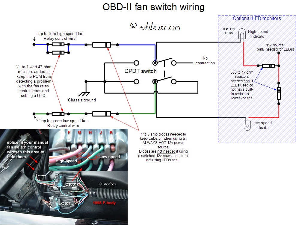
Last i dont quite understand the led lingo based off of shoeboxs diagram, i barely understand some of it
Thanks for your patience
3 resistors
http://www.radioshack.com/product/in...ductId=2062313
Toggle switch
http://www.radioshack.com/product/in...ductId=2062506
and does the wire matter?
Am i able to just splice in since i dont know how to solder, i read in some past searches about wire taps? Would this be an option?
Last i dont quite understand the led lingo based off of shoeboxs diagram, i barely understand some of it
Thanks for your patience

Launching!
Joined: Jan 2012
Posts: 211
Likes: 0
From: baltimore maryland
not trying to bash your desire to learn, but if your not to sure of the wiring, how to make the connections, and dont want to overheat your engine/fry your PCM from hooking something up wrong, SLP makes a fan control switch that is simple plug and play. 70 bucks but peace of mind and reliability are worth it to me.
TECH Resident
Joined: Apr 2010
Posts: 787
Likes: 0
From: T E X A S
70 bucks vs 12, and some know how/research... ill take the time myself and pocket the rest.
I tapped the high and low speed into a cheap switch from autozone, then ran another wire from the switch to a ground on the chassis... simple and it works flawlessly.
I tapped the high and low speed into a cheap switch from autozone, then ran another wire from the switch to a ground on the chassis... simple and it works flawlessly.
The 3 resistors, (2 high speed, 1 low speed) are they necessary for OBD1? I thought I read that they are not because it will not set a DTC on OBD1. Just making sure..
I'm with slowz28... I'll save the extra $45 any day for 20 minutes of research.
I'm with slowz28... I'll save the extra $45 any day for 20 minutes of research.
and does the wire matter?
Finding wire that is the same size as wires your tapping in to would probably be optimal.
Am i able to just splice in since i dont know how to solder, i read in some past searches about wire taps? Would this be an option?
I've never seen one of those before, but it seems like it should work.
Last i dont quite understand the led lingo based off of shoeboxs diagram, i barely understand some of it
What exactly are you not understanding? This will help us help you.
Sorry for the double post, forgot to reply to questions in the last message lol..
TECH Veteran


Joined: Dec 2008
Posts: 4,145
Likes: 61
From: Little Rock, AR
Trending Topics
ok so i dont know whats going on here but my switch isnt working, im gonna attach some pictures to see if you all can help me out. thanks in advance
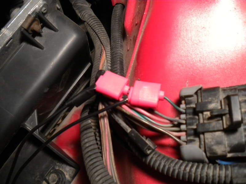
this is a picture of how i wire tapped the high and low speed wires
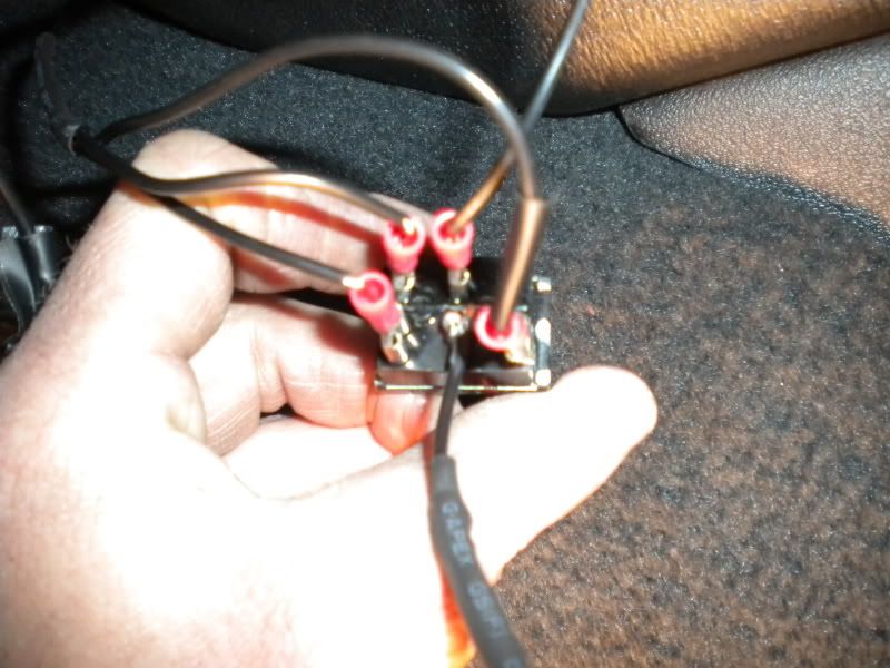
this is how i wired my switch , hopefully you can understand but i placed it the same way i viewed the diagram in my 1st post
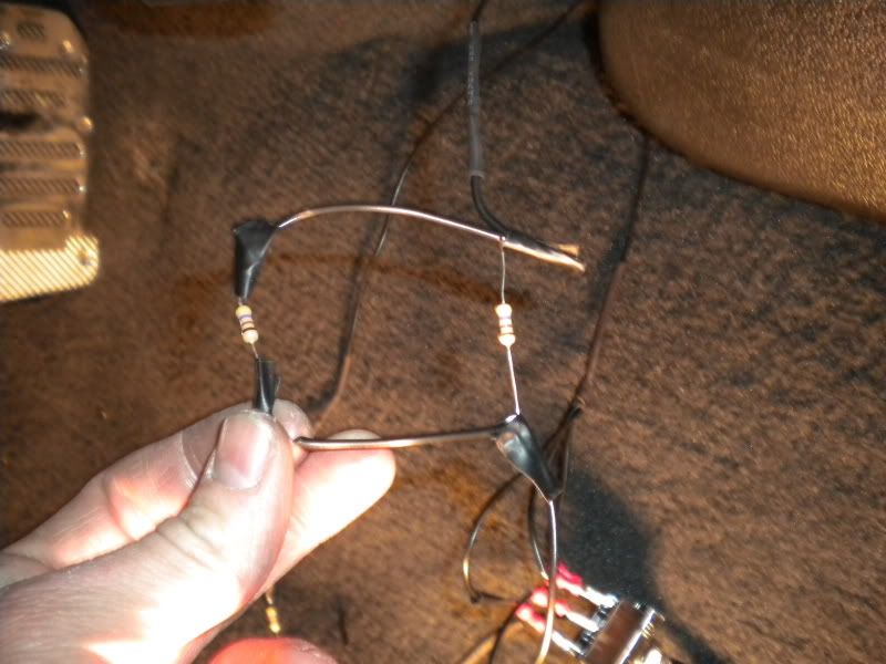
this is how i wired my high speed fan
this is how i wired my low speed fan
this is a picture of how i wire tapped the high and low speed wires
this is how i wired my switch , hopefully you can understand but i placed it the same way i viewed the diagram in my 1st post
this is how i wired my high speed fan
this is how i wired my low speed fan
LS1 Tech Stories
The Best V8 Stories One Small Block at Time

6 Common C5 Corvette Failures and What's Involved In Repairing Them
Pouria Savadkouei
Retro Modern Bandit Pontiac Trans AM Comes With Burt Reynolds' Autograph
Verdad Gallardo
Top 10 Greatest Cadillac V Series Performance Models Ever, Ranked
Pouria Savadkouei
Top 10 Most Powerful Chevy Trucks Ever Made!

Hennessey's New Supercharged Silverado ZR2 Has 700 HP
Verdad Gallardo
Coachbuilt N2A Anteros Is an LS2-Powered C6 Corvette In Italian Clothes
Verdad Gallardo
Awesome K5 Blazer Restomod Comes With C7 Corvette Power
Verdad Gallardo
10 Camaros You Should Never Buy

10 LS Engine Myths That Refuse to Die
Verdad Gallardo Launching!
Joined: Jan 2012
Posts: 211
Likes: 0
From: baltimore maryland
those scotch locks are a timebomb, they work for a while, but eventually they lose connection and either burn up, or cut the copper, and then the wire burns up. go buy a soldering iron, depot sells them reasonably, get a click to start butane model. practice on some other wire, then move to your project. make sure to buy flux cored solder. its not that hard and in an hour youll be an expert. if you cant get it after the hour, buy the SLP fan mod switch, it will cost you less in the long run
ive been practicing soldering so i will definiitly do that to the switch, i do also have a mulitimeter that measures resistance,
i dont know if its worth mentioning but for my ground i connected the far left two (top and bottom) and the bottom right together to complete my ground. My resistors are 470ohm 1/2 watt 5% tolerance
i dont know if its worth mentioning but for my ground i connected the far left two (top and bottom) and the bottom right together to complete my ground. My resistors are 470ohm 1/2 watt 5% tolerance

Launching!
Joined: Jan 2012
Posts: 211
Likes: 0
From: baltimore maryland
i know the pic is of a 95, not a 96 or 97, but the wire colors are different in the pic, do you have the right harness?
all your effectivly doing is grounding the different leads that are normally controlled by the computer.
grounding the green wire turns on the control relay for the low speed fans
grounding both the green and the blue turns on the high speed fans.
start with your meter on the ohm setting and touch the two leads together, the ohm reading should be 0 or close to it depending upon the sensitivity of the meter. regardless of reading, we only really need the touching reading (electrical continuity) and the not touching reading( not electrically continuous)
put one lead on a good ground, the outside of the cigarette lighter is what i use, and test the leads of the wires that you intentionally grounded, there are 3 at the switch.
with the switch in the off (middle) position, test the top left, lower left, and lower right terminal of the switch to ground as you have it pictured above. you should read continuity, if not fix it.
now put the switch in the low speed position (switch to the side with the single connection on the right as pictured) and you should read ground on the middle lower terminal. if not fix it
now switch to the high speed setting and test the lower middle and upper middle terminals to ground. if you have ground on both middle terminals you should be good to go inside the car.
now move under the hood and unplug your haness you have spliced into. with one test lead on the ground battery terminal, the other lead stuck in the end of the connector, test the green wire to ground, and the blue wire to ground. somewhere there is a bad connection and youll find it.
inside the engine bay your meter will read higher resistance to ground as compared to inside the car, do nto worry this is normal as the resistors you put in are causing the spike in resistance.
if everything tests out, i believe you have spliced into the wrong harness, if you dont get a ground where your supposed to, you have a bad connection.
Launching!
Joined: Jan 2012
Posts: 211
Likes: 0
From: baltimore maryland
yea the 3 wires that all go to ground are fine piggybacked together as long as they all have good connections, the scotchlocks that you need to replace are the ones under the hood. everyone calls them something different, but i make a lot of money fixing peoples work that use them.
for the connections at the switch, use a good crimping tool such as this one and use the same style terminal connectors you currently have. its tough to see the crimps in the pic, but the tool below is what i use.
http://www.homedepot.com/h_d1/N-5yc1...&storeId=10051
brand isnt that important, klein makes very nice tools, but i know channel locks makes a good set too at less cost for a one time use tool. use the part with the tit to make the crimp.
as far as the ratings on the resistors, i leave that to shbox and his website, he hasnt led anyone astray yet, so i trust it
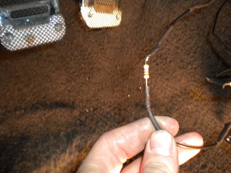
also if you see copper showing, thats too much insulation stripped away, either cut it and try again, or tape it up. shrinkwrap the entire resistor, not just taping the ends up
for the connections at the switch, use a good crimping tool such as this one and use the same style terminal connectors you currently have. its tough to see the crimps in the pic, but the tool below is what i use.
http://www.homedepot.com/h_d1/N-5yc1...&storeId=10051
brand isnt that important, klein makes very nice tools, but i know channel locks makes a good set too at less cost for a one time use tool. use the part with the tit to make the crimp.
as far as the ratings on the resistors, i leave that to shbox and his website, he hasnt led anyone astray yet, so i trust it
also if you see copper showing, thats too much insulation stripped away, either cut it and try again, or tape it up. shrinkwrap the entire resistor, not just taping the ends up
TECH Veteran
Joined: Dec 2008
Posts: 4,145
Likes: 61
From: Little Rock, AR
ive been practicing soldering so i will definiitly do that to the switch, i do also have a mulitimeter that measures resistance,
i dont know if its worth mentioning but for my ground i connected the far left two (top and bottom) and the bottom right together to complete my ground. My resistors are 470ohm 1/2 watt 5% tolerance
i dont know if its worth mentioning but for my ground i connected the far left two (top and bottom) and the bottom right together to complete my ground. My resistors are 470ohm 1/2 watt 5% tolerance
The little dabs of tape and exposed bare wire are ok for testing, but you don't want to leave it like that. Nothing should be bare or showing anywhere.
Your parallel resistors can sit right next to each other. Just twist the legs together on each end, then connect that to the wire (like it's one resistor). Then cover the whole thing with heat shrink. Much neater that way.