







Reverse lockout solenoid. How does it work??

Thread Starter
10 Second Club
iTrader: (25)
Joined: Dec 2004
Posts: 2,554
Likes: 1
From: Kannapolis, NC
 Reverse lockout solenoid. How does it work??
 What exactly turns the solenoid on? A certain mph or any forward movement? 2nd when the lockout is active will the cltch pedal being pushed in un-activate the solenoid? Ex.. If you were cruising at 20 mph with the solenoid active and pushed in the clutch would the solenoid still be active? Thanks for the help.
The reverse lockout is operated from a clutch pedal position switch that inputs into C1-32 and the PCM operates (grounds) the reverse lockout through C2-44. If you want to use it you'll have to somehow get a normally closed switch in your clutch pedal linkage, the circuit is "hot" until you depress the clutch, when it goes "open" the PCM will ground the lockout solenoid.
Good info on this link.
http://www.ls2.com/boggs/torques/enginetorques.htm
.
Good info on this link.
http://www.ls2.com/boggs/torques/enginetorques.htm
.
Last edited by bearcatt; Aug 13, 2009 at 01:15 AM.
Clutch pedal position has nothing to do with the function of the reverse lockout solenoid. If so, it would activate the solenoid every time the clutch was depressed. This can easily be tested with the car off, ignition off...regardless of clutch pedal position the reverse lockout will block you from going into reverse (because there is no power supply with the ignition off). With the ignition on, the solenoid opens allowing the shifter to move into reverse....with or without the clutch being pressed down.
The pcm does supply the ground, and it grounds the circuit based on vehicle speed. I believe it grounds the lockout solenoid at speeds of 5 mph or below.
The pcm does supply the ground, and it grounds the circuit based on vehicle speed. I believe it grounds the lockout solenoid at speeds of 5 mph or below.
The reverse lockout is operated from a clutch pedal position switch that inputs into C1-32 and the PCM operates (grounds) the reverse lockout through C2-44. If you want to use it you'll have to somehow get a normally closed switch in your clutch pedal linkage, the circuit is "hot" until you depress the clutch, when it goes "open" the PCM will ground the lockout solenoid.
If that's only how the 1999 and up stuff works then I'm going to have to install a Manual Switch for myself, it'll be easier then all that wiring for the Switch on the Clutch Petal.

Heres what alldata says about an '01 :
Reverse Inhibit Description and Operation
The reverse inhibit solenoid is a safety feature which prevents an inadvertent shift into reverse at speeds above 5 km/h (3 mph) . The system consists of the following components:
The Powertrain Control Module (PCM) .
The reverse inhibit solenoid.
With the ignition ON battery voltage is supplied directly to the reverse inhibit solenoid. At forward speeds above 5 km/h (3 mph) the PCM grounds the control circuit of the reverse inhibit solenoid. This energizes the solenoid and mechanically blocks the shift lever from going into the REVERSE position.
And heres the wiring diagram:
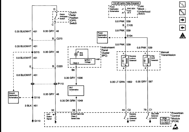
This is the way the 98's function as well as the old LT1 stuff also...
Reverse Inhibit Description and Operation
The reverse inhibit solenoid is a safety feature which prevents an inadvertent shift into reverse at speeds above 5 km/h (3 mph) . The system consists of the following components:
The Powertrain Control Module (PCM) .
The reverse inhibit solenoid.
With the ignition ON battery voltage is supplied directly to the reverse inhibit solenoid. At forward speeds above 5 km/h (3 mph) the PCM grounds the control circuit of the reverse inhibit solenoid. This energizes the solenoid and mechanically blocks the shift lever from going into the REVERSE position.
And heres the wiring diagram:
This is the way the 98's function as well as the old LT1 stuff also...
Trending Topics
So then I won't need that Clutch Switch. I know up there we were talking about it but after thinking about it I beleive that Switch on the Cluch Petal mainly controls the Cruise Control On/Off, the Rev Lockout functions like we all have just said.
Won't know till I try it I guess.
Won't know till I try it I guess.
LS1 Tech Stories
The Best V8 Stories One Small Block at Time

Gas Monkey Built a 6-Wheel Ferrari Testarossa With a Corvette LT4 Engine
Verdad Gallardo
7 Most Reliable High-Performance Engines GM Has Ever Built
Verdad Gallardo
Amazing '71 Camaro Restomod Is Modern Muscle Car Under the Skin
Verdad Gallardo
6 Common C5 Corvette Failures and What's Involved In Repairing Them
Pouria Savadkouei
Retro Modern Bandit Pontiac Trans AM Comes With Burt Reynolds' Autograph
Verdad Gallardo
Top 10 Greatest Cadillac V Series Performance Models Ever, Ranked
Pouria Savadkouei
Top 10 Most Powerful Chevy Trucks Ever Made!

Hennessey's New Supercharged Silverado ZR2 Has 700 HP
Verdad Gallardo
Coachbuilt N2A Anteros Is an LS2-Powered C6 Corvette In Italian Clothes
Verdad Gallardo Thread Starter
10 Second Club
iTrader: (25)
Joined: Dec 2004
Posts: 2,554
Likes: 1
From: Kannapolis, NC
I am trying to hook up my 2 step off the clutch switch. However, the 98's do not have a pcm input for the switch so I am trying to figure something else. Maybe the cruise control module. I just want to run to something under the hood instead of running a single wire into the car.


I've got a T-56 in a 3rd gen.
I run a wire from the solenoid to a switch.
1st I had a switch on top of the shift ****- those ***** were a bit cheesy, so I switched to one in the ash tray.
The solenoid is right near the shift gate,so a wire to the console area is easy.
You can break through the gate by using some oomph, but that is a when all else fails fall back.
YOU DO have to remember to turn the switch off. It will drain your battery if you leave it on.... plus you can fetch the wrong gear when in a hurry ;-(
I run a wire from the solenoid to a switch.
1st I had a switch on top of the shift ****- those ***** were a bit cheesy, so I switched to one in the ash tray.
The solenoid is right near the shift gate,so a wire to the console area is easy.
You can break through the gate by using some oomph, but that is a when all else fails fall back.
YOU DO have to remember to turn the switch off. It will drain your battery if you leave it on.... plus you can fetch the wrong gear when in a hurry ;-(
I am trying to hook up my 2 step off the clutch switch. However, the 98's do not have a pcm input for the switch so I am trying to figure something else. Maybe the cruise control module. I just want to run to something under the hood instead of running a single wire into the car.
Didn't realize the 1998s are so different.
The 1998 still has a Reverse Inhibit Solenoid Control it's just in a different location.
It's located on block section C1 pin 42 LT/GRN wire.
It does the same thing at a different location.
Where is the cruise control inhibit or enable pin on the 1998 PCM pinout ( don't see it ) ?
You only need to connect a switch from ground to the reverse lockout somehow ?
.
^^The 1998's have a Cruise Control Module like the LT1 Cars..1999-up is when the PCM started controlling it, that Clutch Anticipation Switch is the main factor of that one.

Here is the Diagram that I found a long time ago..
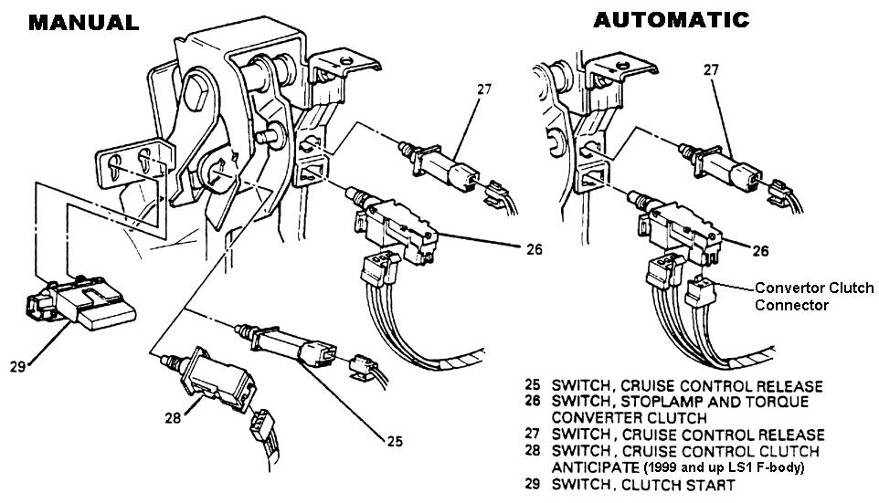
From what I figure and seen that switch is for the Cruise dis-engage, and to help do something with the Idle when you push in the Clutch. It controls 2 seperate circuits with the 4 wires that go into it..two of the go to the Cruise Circuit, the other two send a ground signal to the PCM (Blue #32, gray wire) to let it know that the Clutch is pushed in..I beleive that is the part that helps with the idle.
I don't have it on mine and I've had no problems so far. I just got it tuned for the T56 setup, so once I get it back together I'll be able to see how it works, but I think the Reverse Lockout should function without a problem cause that goes just off of speed like we were talking about above. Even with mine tuned as an Auto I had no idle problems so I think I will be good.
Basically that switch really isnt needed if you have a tuned Engine..it can be easily wired around.
From what I figure and seen that switch is for the Cruise dis-engage, and to help do something with the Idle when you push in the Clutch. It controls 2 seperate circuits with the 4 wires that go into it..two of the go to the Cruise Circuit, the other two send a ground signal to the PCM (Blue #32, gray wire) to let it know that the Clutch is pushed in..I beleive that is the part that helps with the idle.
I don't have it on mine and I've had no problems so far. I just got it tuned for the T56 setup, so once I get it back together I'll be able to see how it works, but I think the Reverse Lockout should function without a problem cause that goes just off of speed like we were talking about above. Even with mine tuned as an Auto I had no idle problems so I think I will be good.
Basically that switch really isnt needed if you have a tuned Engine..it can be easily wired around.
Last edited by the_merv; Aug 14, 2009 at 08:42 AM.
^^ I don't think it will even be an issue on your car, I would think the reverse lockout should work properly from the PCM.
Here's an explanation of the clutch anticipation switch I found when doing a search.
https://ls1tech.com/forums/3150589-post2.html
The clutch anticipate switch is just what it says. It lets the PCM know when your about to shift so it can flare the engine up a little between shifts. It also tells the PCM to shut off cruise control when you touch the clutch pedal. And yes pin D blk/wht wire goes to ground and the other pin C gry wire goes to the PCM connector C1 pin 32. At least on a 99 f body but it should be the same from 99 on up.
I would like to say sorry for responding to you guys with incorrect information in response to 03 BUSA's original post. Jonathan@Tick was spot on. Great diagrams from Jonathan@Tick and you the_merv.
the_merv I see you changed your Avatar. Honestly I thought your older one with the shifting was cool.
.
Here's an explanation of the clutch anticipation switch I found when doing a search.
https://ls1tech.com/forums/3150589-post2.html
The clutch anticipate switch is just what it says. It lets the PCM know when your about to shift so it can flare the engine up a little between shifts. It also tells the PCM to shut off cruise control when you touch the clutch pedal. And yes pin D blk/wht wire goes to ground and the other pin C gry wire goes to the PCM connector C1 pin 32. At least on a 99 f body but it should be the same from 99 on up.
I would like to say sorry for responding to you guys with incorrect information in response to 03 BUSA's original post.
Jonathan@Tick was spot on. Great diagrams from Jonathan@Tick and you the_merv.the_merv I see you changed your Avatar. Honestly I thought your older one with the shifting was cool.
.

Thread Starter
10 Second Club
iTrader: (25)
Joined: Dec 2004
Posts: 2,554
Likes: 1
From: Kannapolis, NC
Is it safe to say that ground completes the circuit for the clutch anticipation switch?? If so I just need to find where it goes into the cruise control module under the hood and tie into that wire.
Yes, run the Pin C gray wire to PCM Blue Connector, Pin # 32, and Pin D ground to a good spot on the Chassis.
Now with Pin A and Pin B, here's what you do..
Take a look at the switch # 27 there in the diagram and find it on your Petals. Take one of the Wires and clip it about 3" away from the Connector(basically give yourself enough to splice it to another wire). Now with that one wire you clipped, run that to Pin A on the Clutch Anticipation Switch Connector and splice it in. With Pin B, splice that to the other clipped wire.
Doing this will make this a series circuit, and when you push the Clutch it will disengage the cruise, as well as if you push in the Brake too.
Refer to this edited diagram if you need to..
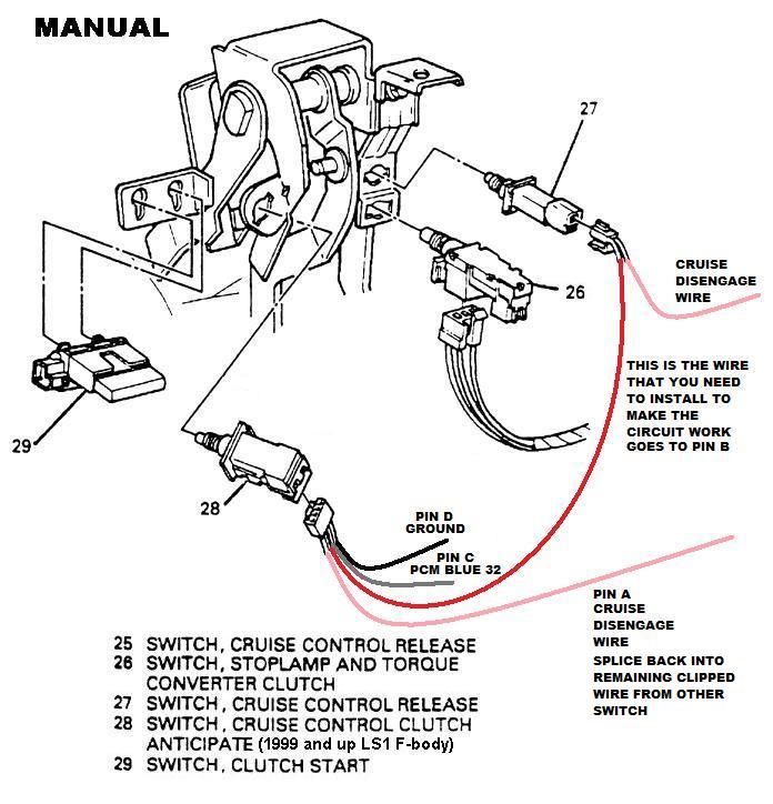
This is the same way I did it, except I used the single Switch on the Brake Petal, moved that over to the Clutch Petal, and re-wired the TCC Switch Connector into the Cruise disengage for the Brake Petal..works flawlessly.
No prob man..it's all good.
I've been messing with avatars..being bored.
Now with Pin A and Pin B, here's what you do..
Take a look at the switch # 27 there in the diagram and find it on your Petals. Take one of the Wires and clip it about 3" away from the Connector(basically give yourself enough to splice it to another wire). Now with that one wire you clipped, run that to Pin A on the Clutch Anticipation Switch Connector and splice it in. With Pin B, splice that to the other clipped wire.
Doing this will make this a series circuit, and when you push the Clutch it will disengage the cruise, as well as if you push in the Brake too.
Refer to this edited diagram if you need to..
This is the same way I did it, except I used the single Switch on the Brake Petal, moved that over to the Clutch Petal, and re-wired the TCC Switch Connector into the Cruise disengage for the Brake Petal..works flawlessly.
I would like to say sorry for responding to you guys with incorrect information in response to 03 BUSA's original post. Jonathan@Tick was spot on. Great diagrams from Jonathan@Tick and you the_merv.
the_merv I see you changed your Avatar. Honestly I thought your older one with the shifting was cool.
Jonathan@Tick was spot on. Great diagrams from Jonathan@Tick and you the_merv.the_merv I see you changed your Avatar. Honestly I thought your older one with the shifting was cool.
I've been messing with avatars..being bored.
Last edited by the_merv; Aug 14, 2009 at 08:55 PM.