

Wiring diagram for LNC-002 and NOS mini controller
 03-10-2012, 06:45 PM
#21

What kind of times have you gotten with the current size shot you are running now?
Kinda don't want this thread to die down as I think it is good for other members that are doing this kind of installation soon to see the right way to do it and just for reference if anyone wanted to use your diagram.
Honestly this should be a sticky on "how to wire your nitrous"

 03-11-2012, 07:43 PM
#23
10 Second Club
Thread Starter
Join Date: Mar 2008
Location: Cape Girardeau, Missouri
Posts: 1,034
Likes: 0
Received 1 Like
on
1 Post
You have an 4L60E car correct?
What kind of times have you gotten with the current size shot you are running now?
Kinda don't want this thread to die down as I think it is good for other members that are doing this kind of installation soon to see the right way to do it and just for reference if anyone wanted to use your diagram.
Honestly this should be a sticky on "how to wire your nitrous"
Thanks man!
03-12-2012, 06:10 AM
#24
On The Tree
iTrader: (1)
Join Date: May 2010
Location: Fort Walton Beach, FL
Posts: 131
Likes: 0
Received 0 Likes
on
0 Posts
Orange LNC wire is the retard activation wire, so it should come on when the fuel/nitrous solenoids are active, not from the arming switch.
Incredible install job!
Incredible install job!
03-12-2012, 08:39 AM
#25
LS1Tech Sponsor

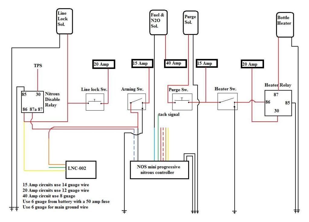
A couple of notes on the LNC and NOS mini controller wiring diagram in the first post.
It appears the nitrous solenoids are not controlled by the arming switch. For safety we would recommend having the nitrous and fuel solenoids also controlled by the arming switch so if something were to go wrong you could disable the solenoids with the arming switch without having to power down the entire car (and possibly causing the steering to lock).
Also if I am reading the diagram correctly it looks like the heater switch will have a direct short to ground when it is turned on.
I drew this up for a friend running these two, basicly to help his install go a little smoother. The Lingenfelter LNC-002 is a launch controller and timing retarder, and the NOS mini controller is a dual stage progressive nitrous controller. I feel pretty confident that this is drawn up correctly. But any questions or comments are welcome!
03-12-2012, 08:48 AM
#26
LS1Tech Sponsor
The orange wire is the retard activation wire but on a progressive system you can't connect that wire to one of the solenoids because the solenoids are being turned on and off so that would turn on and off the retard activation.
If the nitrous controller has an analog voltage output wire that can be enabled when the nitrous is active then that is the preferred method to trigger the timing retard. I don't know if the NOS mini controller has a analog output.
On multi-stage progressive systems, if you aren't using the second stage of nitrous, you can set the second stage to be 100% on when ever the first stage is on (same activation criteria but don't make it progressive) and then use the output for the second stage to trigger the timing retard.
If those options aren't possible then you have to have the nitrous timing retard active when ever the arming switch is active. I don't know of any other way to do it (but I would like to hear of any).
03-12-2012, 06:51 PM
#28
10 Second Club
Thread Starter
Join Date: Mar 2008
Location: Cape Girardeau, Missouri
Posts: 1,034
Likes: 0
Received 1 Like
on
1 Post
A couple of notes on the LNC and NOS mini controller wiring diagram in the first post.
It appears the nitrous solenoids are not controlled by the arming switch. For safety we would recommend having the nitrous and fuel solenoids also controlled by the arming switch so if something were to go wrong you could disable the solenoids with the arming switch without having to power down the entire car (and possibly causing the steering to lock).
Also if I am reading the diagram correctly it looks like the heater switch will have a direct short to ground when it is turned on.
It appears the nitrous solenoids are not controlled by the arming switch. For safety we would recommend having the nitrous and fuel solenoids also controlled by the arming switch so if something were to go wrong you could disable the solenoids with the arming switch without having to power down the entire car (and possibly causing the steering to lock).
Also if I am reading the diagram correctly it looks like the heater switch will have a direct short to ground when it is turned on.
Also the ground wire to the heater switch is to let the LED light light up, it won't actually be connected to 12V.
The orange wire is the retard activation wire but on a progressive system you can't connect that wire to one of the solenoids because the solenoids are being turned on and off so that would turn on and off the retard activation.
If the nitrous controller has an analog voltage output wire that can be enabled when the nitrous is active then that is the preferred method to trigger the timing retard. I don't know if the NOS mini controller has a analog output.
On multi-stage progressive systems, if you aren't using the second stage of nitrous, you can set the second stage to be 100% on when ever the first stage is on (same activation criteria but don't make it progressive) and then use the output for the second stage to trigger the timing retard.
If those options aren't possible then you have to have the nitrous timing retard active when ever the arming switch is active. I don't know of any other way to do it (but I would like to hear of any).
If the nitrous controller has an analog voltage output wire that can be enabled when the nitrous is active then that is the preferred method to trigger the timing retard. I don't know if the NOS mini controller has a analog output.
On multi-stage progressive systems, if you aren't using the second stage of nitrous, you can set the second stage to be 100% on when ever the first stage is on (same activation criteria but don't make it progressive) and then use the output for the second stage to trigger the timing retard.
If those options aren't possible then you have to have the nitrous timing retard active when ever the arming switch is active. I don't know of any other way to do it (but I would like to hear of any).
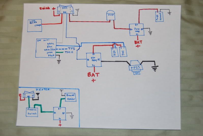
I like the idea of connecting the retard activation wire to the second stage, this car will not have a second stage at the moment. But it may get one down the road, so I dont think we will wire it up that way. The nos controller does have a control output for each stage, but it only switches the ground, and since the lnc-002 needs 12v activation it wont work for this situation. So the way I have it wired up is it will get the timing pulled as soon as the arming switch is on, I don't think that will cause any issues with the current setup.
Thanks for taking the time to look at this, I apprieceate it! Feel free to correct me if im wrong, I love feed back!
03-12-2012, 09:05 PM
#29

I did a buddies like this on his 5th gen. I wired the orange wire to the arming switch so it pulls timing as soon as the switch is on. He made a pull on the dyno on motor first, then we removed the solenoid ground and activated the box and made another motor pull and you could tell timing was pulled because it made like 20-25 hp less.
03-13-2012, 08:35 AM
#30
LS1Tech Sponsor
We are probably 4 to 6 weeks from being ready to release the NCC-001 to the public, hopefully not any more than that. We are making some software changes to further expand the capabilities and improve some areas that have shown up in the initial testing and beta test units. The production circuit boards are done. The biggest potential delay will be getting the user manual done - lots of features equals lots of stuff to explain.
 03-13-2012, 11:45 AM
#32
LS1Tech Sponsor
Ok, I didn't realize that was left out of the diagram. My concern would be if other people are using that diagram to wire up the nitrous and they too don't realize that has been omitted.
I think you may just be interpreting my diagram wrong. This is going to be wired to a direct port intake and I didnt feel like drawing all of the solenoids in, so it just says "fuel and N2O solenoids" The nos mini controller switches the ground to them so if the arming switch is turned off it will kill power to the nitrous controller and disable the solenoids.
Also the ground wire to the heater switch is to let the LED light light up, it won't actually be connected to 12V.
I like the idea of connecting the retard activation wire to the second stage, this car will not have a second stage at the moment. But it may get one down the road, so I dont think we will wire it up that way. The nos controller does have a control output for each stage, but it only switches the ground, and since the lnc-002 needs 12v activation it wont work for this situation. So the way I have it wired up is it will get the timing pulled as soon as the arming switch is on, I don't think that will cause any issues with the current setup.
Thanks for taking the time to look at this, I apprieceate it! Feel free to correct me if im wrong, I love feed back!
03-13-2012, 04:16 PM
#33
The only problem I see with having the timing pulled as soon as the activation switch is switched on is if it's a automatic equipped car and the owner is launching at 2500rpm or more or launching off a transbrake.
When spraying a big shot like 250 or more(10* timing pulled at least) it's going to be hard to get up on the stall speed of a tight nitrous converter.
That's why you need to use the analog outputs on the nitrous controller to activate the retard when the fuel and nitrous solenoids become active.
Cape T/A even though the LNC uses 12v activation and the nos mini uses ground you can use a relay to switch the ground to 12v through the relay.
Also I was under the assumption that the LNC was able to use ground or 12v for the retard function?
03-13-2012, 09:12 PM
#34
10 Second Club
Thread Starter
Join Date: Mar 2008
Location: Cape Girardeau, Missouri
Posts: 1,034
Likes: 0
Received 1 Like
on
1 Post
Well, what I read on the instructions it came off that it could only have a 12v to trigger the retard feature. I suppose adding another relay could work to, good idea.
03-13-2012, 09:15 PM
#35
10 Second Club
Thread Starter
Join Date: Mar 2008
Location: Cape Girardeau, Missouri
Posts: 1,034
Likes: 0
Received 1 Like
on
1 Post
Good point, I guess when I posted this I wasn't intending for people to use this diagram. So, use it at your own risk people!!!! Lol, thanks again for the input.
03-13-2012, 09:49 PM
#36
Yea a simple relay from Radio Shack will work.
Another question.....I went to Radio Shack today to get my terminal strip and I saw the one you have, but I could not for the life of me figure out how you are using it as a common ground for all your grounds when there is no wire or specific terminal for that ground circuit to attach to. I know you said you jumpered them to a central point for your main ground circuit that uses the heaviest gauge wire you specified, but I couldn't figure out how to use the extra jumper strip they had to do that with the terminal strip.
Are each of the individual terminals that each ground wire connects to ground points?
03-14-2012, 05:36 AM
#37
10 Second Club
Thread Starter
Join Date: Mar 2008
Location: Cape Girardeau, Missouri
Posts: 1,034
Likes: 0
Received 1 Like
on
1 Post
Yes, they are all grounds, I'll try and find a pic for you later today of the jumper strip. It's just a thin piece of metal that goes under one side of the screws and I put my wire (with a fork terminal) on the other side.
03-14-2012, 06:47 AM
#38
I guess my question should be this as I realize that all of them are grounds, but will the terminal for each (-) wire be grounded by just connecting the - wire to the terminal strip? Or will I need to use the jumper strip to create the ground source with a main 8 ga. wire like you did?
03-15-2012, 08:51 PM
#40
LS1Tech Sponsor
I agree having the timing retard active all the time would not be optimal - I was just trying to come up with a possible solution for this install.
You could also use an RPM switch to activate the timing retard only above a certain RPM or a MPH switch to activate the timing retard only once you were moving.
The LNC-002 (and its replacement the LNC-2000) offer +12v or ground activation for the RPM limiter (2-step) but only +12v activation for the timing retard. You could use a relay to reverse this if you need to use a ground to trigger the retard though.
The only problem I see with having the timing pulled as soon as the activation switch is switched on is if it's a automatic equipped car and the owner is launching at 2500rpm or more or launching off a transbrake.
When spraying a big shot like 250 or more(10* timing pulled at least) it's going to be hard to get up on the stall speed of a tight nitrous converter.
That's why you need to use the analog outputs on the nitrous controller to activate the retard when the fuel and nitrous solenoids become active.
Cape T/A even though the LNC uses 12v activation and the nos mini uses ground you can use a relay to switch the ground to 12v through the relay.
Also I was under the assumption that the LNC was able to use ground or 12v for the retard function?
When spraying a big shot like 250 or more(10* timing pulled at least) it's going to be hard to get up on the stall speed of a tight nitrous converter.
That's why you need to use the analog outputs on the nitrous controller to activate the retard when the fuel and nitrous solenoids become active.
Cape T/A even though the LNC uses 12v activation and the nos mini uses ground you can use a relay to switch the ground to 12v through the relay.
Also I was under the assumption that the LNC was able to use ground or 12v for the retard function?