


Nitrous Related Wiring
I know it's asking alot, but you guys seem to be pretty damn good with this wiring stuff.
How about mixing that FJO diagram in a dual stage with the transbrake/linelock diagram that I was just asking about. I've got both in front of me, and I'm trying to figure where that red/white off the FJO is going to go
How about mixing that FJO diagram in a dual stage with the transbrake/linelock diagram that I was just asking about. I've got both in front of me, and I'm trying to figure where that red/white off the FJO is going to go
Originally Posted by Slow Z28
I know it's asking alot, but you guys seem to be pretty damn good with this wiring stuff.
How about mixing that FJO diagram in a dual stage with the transbrake/linelock diagram that I was just asking about. I've got both in front of me, and I'm trying to figure where that red/white off the FJO is going to go
How about mixing that FJO diagram in a dual stage with the transbrake/linelock diagram that I was just asking about. I've got both in front of me, and I'm trying to figure where that red/white off the FJO is going to go
Here's another wiring diagram and quote from the famous and handsome (I guess), NX Ricky.
[QUOTE NX Ricky]The idea behind this is when you push/lock in the trans brake, and release your foot brake waiting to launch the car settles. You can see at the track some cars tires move a smedge and the car seems to relax. What that is, everthing from the transmission rearward touching parts have become NONtouching. Like your ring gear, etc.
So you release the brake and now all those non-touching parts slam into each other.
With this wiring in place when you push the transbrake your linelock and front brakes will stay applied. Keeping the car stage, ready for launch. I know it saved my gears from breaking, cheap old street gears.
Anyway thought I would just throw it out there.
Warrning!!! If the diode fails your line lock could activate the transbrake choose the diode appropiate for the amp draw you would to control.[/QUOTE]
Robert
Thanks Robert. I had just made a post about that in which Ricky responded with that diagram as well as another one.
I'm just a little slow with this stuff, so I'm trying to figure out where the small red wire that is the "trigger" for the transbrake, where that wire gets tossed into the mix with that linelock/transbrake setup.
I'm just a little slow with this stuff, so I'm trying to figure out where the small red wire that is the "trigger" for the transbrake, where that wire gets tossed into the mix with that linelock/transbrake setup.
Originally Posted by Slow Z28
that's right, i was just a little slow on the typing. i mean that small red wire for the trigger switch of the transbrake
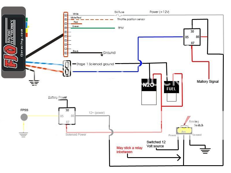
Here's the link to the diagram. Scroll all the way down to the bottom and there is an illustration for your setup. http://www.fjoracing.com/products/2s...%20rev%20G.pdf
i guess my question, now that i figured how to word it properly, would be this:
for the trigger wire, how would it be wired in?
A) do you have one wire from the TB solenoid to a ground, then the other wire go to the trigger switch of the FJO box and it's getting power from the power supply wire of the box?
B) do you have the one wire from the TB solenoid to the power source, then the other wire to the trigger input of the FJ box and it's getting the ground through the ground of the box?
C) you splice together the wire from the FJO box, and if so WHICH wire?
if it's the power source, wouldn't that mean that the box is getting the power no matter if the solenoid was activated or not?
LS1 Tech Stories
The Best V8 Stories One Small Block at Time

Topdon ONE vs. Artidiag 800 BT2: Which is the Diagnostic Tablet For You?
Pouria Savadkouei
Gas Monkey Built a 6-Wheel Ferrari Testarossa With a Corvette LT4 Engine
Verdad Gallardo
7 Most Reliable High-Performance Engines GM Has Ever Built
Verdad Gallardo
Amazing '71 Camaro Restomod Is Modern Muscle Car Under the Skin
Verdad Gallardo
6 Common C5 Corvette Failures and What's Involved In Repairing Them
Pouria Savadkouei
Retro Modern Bandit Pontiac Trans AM Comes With Burt Reynolds' Autograph
Verdad Gallardo
Top 10 Greatest Cadillac V Series Performance Models Ever, Ranked
Pouria Savadkouei
Top 10 Most Powerful Chevy Trucks Ever Made!

Hennessey's New Supercharged Silverado ZR2 Has 700 HP
Verdad Gallardo heres a simple quick link to a TNT F1 wiring, i had trouble finding out what wire went to what terminal on the relay, http://www.nitrous-power.com/instruction.htm
Originally Posted by 01'WS6
Will this setup work on a digital window switch the same way?
Robert


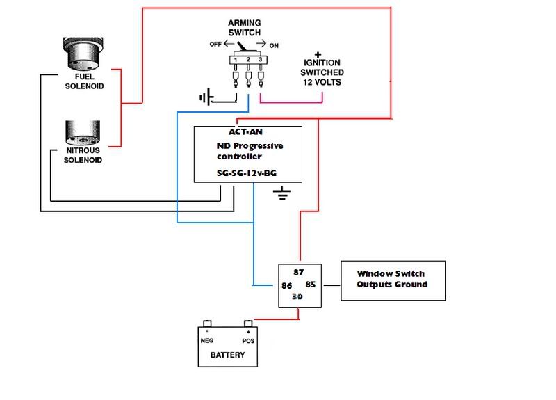
Act: Activation power for noids in
SG: From Solenoid Ground (one pair noids)
SG: From Solenoid Ground (one pair noids)
(can do four large noids)
BG: To Body Ground
12v: Arm switch keyed 12v supply for unit
Pic thanks to Scapaldo.
Robert
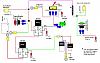
Here's the dual stage dry set-up using the 5177. This is exactly the way I had my 5177 set-up. Note in this shematic it's using a MSD WS and a MSD RPM activation sw, I ran it this way with the first gear lock out I posted earlier for second stage.

Robert
Robert
Originally Posted by Robert56
Trick Window SW Wirirng

Robert
Robert
Robert,
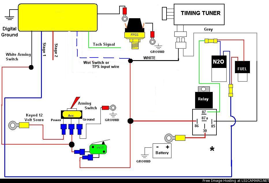
I am looking at this diagram and wondering why the Trick window switch shows a blue wire going to the TPS or WOT switch and then the WOT switch pictured is not connected to that wire at all? The WOT switch instead shows one wire going to The Acc terminal on the arming switch and the other wire going to #86 on the relay. I am kind of a newb when it comes to wiring so I'm sure you have a good reason, I am just trying to learn how to get my setup to work. Thanks.
Originally Posted by ARCTICWHITE98Z28
Robert,
I am looking at this diagram and wondering why the Trick window switch shows a blue wire going to the TPS or WOT switch and then the WOT switch pictured is not connected to that wire at all? The WOT switch instead shows one wire going to The Acc terminal on the arming switch and the other wire going to #86 on the relay. I am kind of a newb when it comes to wiring so I'm sure you have a good reason, I am just trying to learn how to get my setup to work. Thanks.
I am looking at this diagram and wondering why the Trick window switch shows a blue wire going to the TPS or WOT switch and then the WOT switch pictured is not connected to that wire at all? The WOT switch instead shows one wire going to The Acc terminal on the arming switch and the other wire going to #86 on the relay. I am kind of a newb when it comes to wiring so I'm sure you have a good reason, I am just trying to learn how to get my setup to work. Thanks.
Robert